Understanding the enhanced catalytic activity of high entropy alloys: from theory to experiment
Bing
Wang
 *a,
Yingfang
Yao
 bc,
Xiwen
Yu
b,
Cheng
Wang
b,
Congping
Wu
*ac and
Zhigang
Zou
abc
aEco-materials and Renewable Energy Research Center (ERERC), School of Physics, Nanjing University, No. 22 Hankou Road, Nanjing 210093, P. R. China. E-mail: bingwang@nju.edu.cn
bCollege of Engineering and Applied Sciences, Nanjing University, No. 22 Hankou Road, Nanjing 210093, P. R. China
cKunshan Innovation Institute of Nanjing University, 1699 Zuchongzhi South Road, Kunshan, Jiangsu 215347, P. R. China
First published on 25th June 2021
Abstract
High-entropy alloys (HEAs) have evolved to be one of the most popular materials in the last decade. Their unique configuration and attractive properties make HEAs one of the most promising catalysts. Although a very limited amount of work has been reported, higher activities of HEAs than traditional catalysts have been confirmed. This review firstly summarizes the current synthetic methods of nanostructured HEA catalysts. Then, four core effects of HEAs, namely high entropy, cocktail effect, lattice distortion and sluggish diffusion, are briefly introduced, and their impacts on the catalytic properties of HEAs are highlighted. The research progress in the application of HEAs in heterogeneous catalysis is subsequently reviewed from the perspectives of both theory and experiment. The relationships among metastable microstructures, substitution effects (i.e. strain, ligand and ensemble effects) and d-band center are discussed in detail, and their impacts on the adsorption energy of intermediates in catalytic reactions are emphasized. We conclude the review with the discussion of the challenges and opportunities of HEA catalysts. Several directions of future HEA research are put forward. The review provides a valuable resource for those interested in these exciting catalytic materials.
1. Introduction
The synthesis and application (e.g. catalysis1 and energy storage2) of high entropy alloys (HEAs) have received considerable attention in the recent years because of their promising properties that exceed the capabilities of a single element (or unary) component. HEAs are defined as alloys containing at least five principal metal atoms in equi-atomic or near equi-atomic ratios (each with concentrations between 5 at% and 35 at%).3 Instead of forming intermetallic phases, HEAs favor the formation of single solid solution states with simple crystalline phases, namely face-centered cubic (FCC), body-centered cubic (BCC) or close-packed hexagonal (HCP) structure.4 The thermal energy in the solid solution state of HEAs is sufficiently high to allow each element to have random positions within the structure.5 An amorphous phase can also form if large atom size difference in HEAs causes severe lattice distortion.6 Specific structures with appropriate compositions offer HEAs superior physicochemical properties to the traditional alloys, such as low-level stacking fault energy, thermal stability, radiation resistance and corrosion resistance.7–15A promising area of research concerns the role of HEAs as heterogeneous catalysts in chemical and electrochemical reactions. The catalytic reactions are expected to be controlled by tuning the composition, surface atomic coordination and electronic configuration of HEAs. These microstructures can directly affect the interaction between intermediate species and catalysts, thus determining the catalytic activity and selectivity. Therefore, engineering the microstructures is a feasible and reasonable approach to make HEAs a promising catalyst with desirable functions. Although the field of HEAs began in 2004,3,16 only in recent years has attention been paid to the catalytic application of HEAs.17 Minimizing the HEA particle size to the micron or even nanometer scale is the key and challenge to the development of efficient HEA catalysts. In 2018, a thermal shock method was reported to alloy dissimilar elements into HEA nanoparticles (NPs), which greatly stimulated the blossom of HEAs in catalysis. A wide range of multicomponent nanoscale HEAs with the desired composition and size can be achieved by controlling the carbothermal shock parameters.18
Based on the results of the limited investigations performed so far, HEAs are expected to be emerging catalytic materials in the future. In this review, the advantages and potential of HEAs as catalysts are showcased based on the current theoretical calculation and experimental results. First, we summarize the current preparation methods of nanostructured HEA catalysts in Chapter 2. The drawbacks of the current synthesis methods are highlighted. Next, the core effects of HEAs (i.e. high entropy, cocktail effect, lattice distortion and sluggish diffusion), which play crucial roles in improving the catalytic performance, are emphasized in Chapter 3. Some unique properties of HEAs resulting from the core effects are then introduced in Chapter 4, including metastable microstructures, substitution effects (i.e. strain, ligand and ensemble effects), d band center and adsorption energy. How these effects modify the d-band is emphasized. In particular, we discuss the mechanisms behind the remarkable catalytic activity and stability induced by these properties. Challenges associated with HEA catalysts are finally clarified, and several perspectives for future research directions and development of HEAs in the field of catalysis are suggested in Chapter 5. This work aims to be a comprehensive and critical review of general interest to communities who focus on efficient catalysts. It can provide guidance for synthesizing high-quality HEA nanoparticles with improved catalytic performance.
2. Synthesis strategies of nanostructured HEAs
Synthesis of HEA catalysts with nanostructures is the foundation for their application in heterogeneous catalysis. The controlled combination of multiple metals in HEAs at the nanoscale provides an effective avenue to tune the properties by maximizing the active surface area-to-volume ratio. Different from their bulk materials, HEA nanostructures possess unique size-dependent optical and electronic properties, followed by their unique chemical properties, which contribute to achieving highly efficient performance in catalysis. The controllable incorporation of multiple immiscible elements into one type of nanoparticle merits untold scientific and technological potential, yet remains a challenge using conventional synthetic strategies. Very recently, some facile and straightforward strategies for the synthesis of HEA nanomaterials have been developed, which shed light on the application of HEAs in catalysis. Moreover, the drawbacks of each strategy, which should be overcome in further research, are also pointed out.2.1 Carbothermal method
Hu et al. used a two-step carbothermal-shock method to alloy up to eight elements into HEA NPs (NPs),18 which makes it an important advance in promoting the development of HEAs (Fig. 1). This strategy involves a 55 millisecond flash heating and cooling of metal precursors on carbon supports at a peak temperature of 2000 K in argon. The high temperature ensures uniform mixtures of multiple elements by fission/fusion mechanisms and catalytically driven particle dispersion mechanism. During the synthesis process, the liquid metal splits to harvest the dispersed surface-bound residual oxygen (O*) on the carbon support. The concentration of O* closely relates to the density of defects on the support. The presence of O* and the use of catalytically active metals allow different compositions into single particles during the carbothermal process. Notably, a higher O* concentration drives more frequent catalyst motion, making the NPs coarser, whereas a lower concentration may result in a decreased mobility, preventing the formation of single NPs.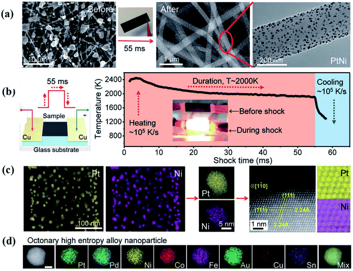 | ||
| Fig. 1 Carbothermal shock synthesis of HEA NPs on carbon nanofiber (CNF). (a) SEM of metal precursors on CNF, and the synthesized PtNi NPs after the carbothermal shock method. (b) Sample preparation and the temporal evolution of temperature during carbothermal shock. (c) Low-magnification and single-particle elemental maps, an HAADF image, and corresponding atomic maps for a PtNi alloy. (d) Elemental maps of an HEA NP composed of Pt, Pd, Ni, Co, Fe, Au, Cu, and Sn. Scale bar, 10 nm. Reproduced from ref. 18 with permission from The American Association for the Advancement of Science. | ||
Although the carbothermal shock method can craft HEA NPs with controllable composition and ultrafine size, it only produces NPs immobilized on a carbon substrate due to the extreme synthetic conditions. It is incompatible with thermally sensitive substrates such as metal, glass, and polymers.
2.2 Electrosynthesis method
In contrast to thermal approaches, electrodeposition is a room-temperature strategy for the synthesis of amorphous metal NPs on conductive substrates.19 Recently, Dick et al. used this method to fabricate high-entropy NPs with up to eight principal components by confining their salt precursors to water nanodroplets suspended in dichloroethane.6 The formation of a ∼10 nm nanodroplet/electrode contact radius leads to the electrodeposition of alloy NPs with disordered microstructures on highly oriented pyrolytic graphite (HOPG) or glassy carbon substrate electrodes.6 The collision of the nanodroplet with the electrode induced an initial sharp rise of current response, followed by a decay due to the consumption of the salts inside the nanodroplets.20 The electrodeposition takes ca. 100 ms to synthesize the HEA NPs with an average diameter of 900 nm.6 The nanodroplet-mediated electrodeposition can prevent phase separation, allowing precise stoichiometric control with 2–5% variability.6Despite many advantages, this method can only produce HEA NPs in the amorphous phase. In addition, it is difficult to achieve uniform immobilization of HEA NPs on granular supports.
2.3 Solvothermal-pyrolysis method
Huang et al. developed a solvothermal-pyrolysis approach to prepare HEA NPs.21 As shown in Fig. 2, typically a nanorod-shaped precursor of quinary metal–organic frameworks (MOFs) on the surface of carbon cloth (CC) was synthesized via a solvothermal method in the solution mixed with salt precursors and 2,5-dihydroxyterephthalic acid.21 Then the precursor was treated by pyrolysis in a H2/Ar mixed atmosphere, which induced decomposition of the MOFs to form single-phase FCC HEA NPs with a diameter of 5 nm.21 The HEA NPs prepared by this method possess many partial dislocations and stacking faults as well as the displacement of atoms, indicating the high distortion of atomic lattices of the NPs. These defects in HEAs result in surface tension, which will significantly affect the catalytic performance. Notably, the pyrolysis process is conducted in a fixed bed pyrolysis reactor. The metal ions are prone to sequential reduction due to their different chemical reductive potentials, causing phase separation.22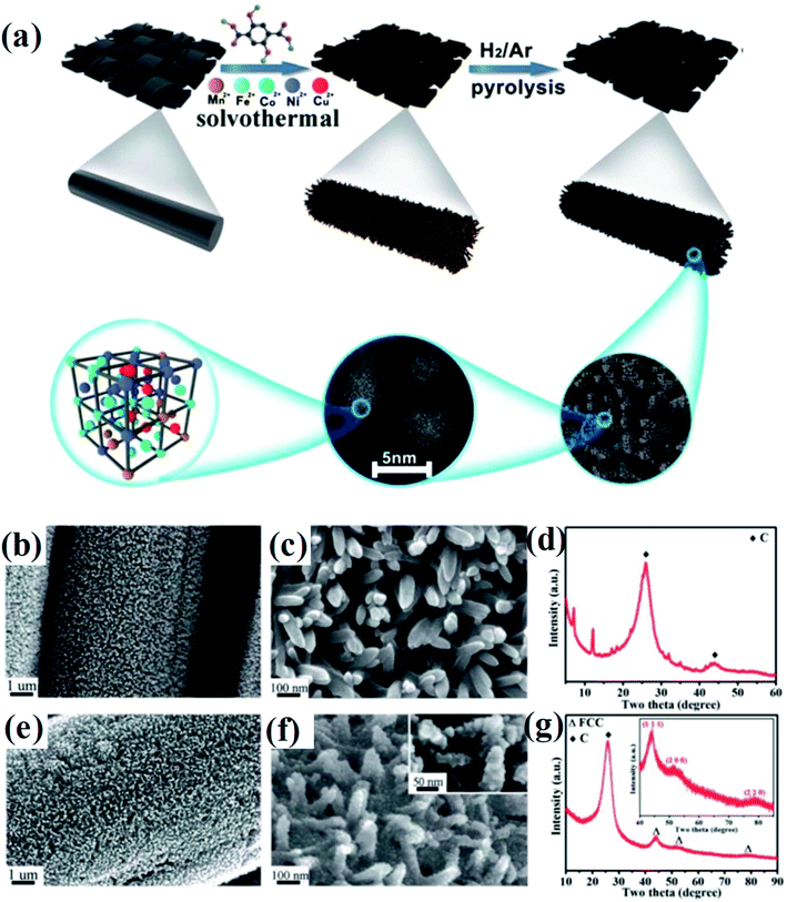 | ||
| Fig. 2 (a) Schematic of the synthesis of HEA composites. (b and c) FESEM images, (d) XRD of quinary MOFs/CC, (e and f) FESEM images, and (g) XRD spectrum of HEA@ N-doped porous carbon on the surface of CC treated at 450 °C. Reproduced from ref. 21 with permission from the Royal Society of Chemistry. | ||
Lu et al. developed a fast-moving bed pyrolysis (FEBP) strategy to synthesize HEA NPs on granular supports including carbon, γ-Al2O3 and zeolite (Fig. 3). This method was conducted at 923 K with a population speed of 20 cm s−1, resulting in the formation of a small size (∼2 nm) of HEA NPs within 5 s. The critical size of HEA nucleus is small enough to reduce excess free energy used for forming nanoalloys, thus avoiding phase separation.23 It is demonstrated that when the time for the precursors to reach the heating zone increases from 5 s to 20 s, obvious phase separation has been found in NPs.24 In the fast moving bed pyrolysis strategy, all metal precursors with different reduction potentials can be decomposed at 923 K.24 The formation of HEA NPs without phase separation is thermodynamically favored because of the low critical free energy.23 In contrast, a slow moving bed pyrolysis causes a larger radius of nuclei, and thus results in phase separation.25
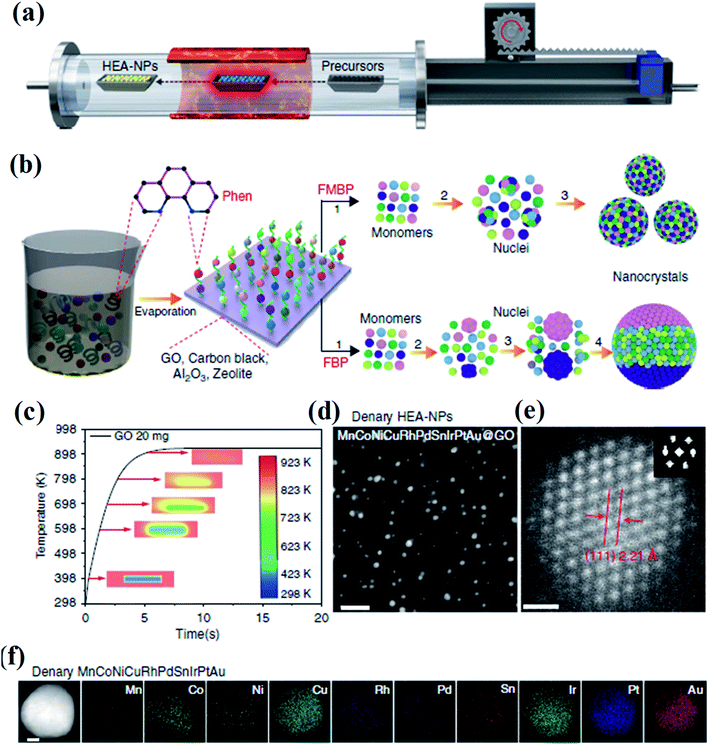 | ||
| Fig. 3 (a) Schematic diagram of the FMBP setup for the synthesis of HEA NPs. (b) Schematic diagrams for the synthesis of homogeneous and phase-separated HEA NPs by FMBP and fast bed pyrolysis (FBP) strategies, respectively. (c) The simulation of the time required for precursors/GO to reach 923 K in the FMBP process. The images in the center show the metal precursors/GO in the quartz boat. (d) HAADF-STEM images for the denary (MnCoNiCuRhPdSnIrPtAu) HEA-NPs highly dispersed on GO synthesized by the FMBP strategy; scale bar, 10 nm. (e) The HRSTEM image for the denary (MnCoNiCuRhPdSnIrPtAu) HEA-NPs (inset: Fourier transform analysis for the denary (MnCoNiCuRhPdSnIrPtAu) HEA-NPs); scale bar, 0.5 nm. (f) Elemental maps for the denary (MnCoNiCuRhPdSnIrPtAu) HEA-NPs. Scale bar, 10 nm. Reproduced from ref. 24 with permission from Springer Nature. | ||
Iversen et al. reported a solvothermal autoclave synthesis method to synthesize HEA NPs at 200 °C in an acetone–ethanol solution with metal precursors.26 Metal chloride salts are prone to yielding the HCP phase, whereas the acetylacetonate precursors craft the FCC phase, due to their different pre-nucleation structures.27 Homogeneous HEA NPs were generated at a temperature lower than the reduction temperature of the metals in HEAs due to autocatalyzed metal reduction at the (111) facets of the FCC phase.28 A Pd core is initially formed which would autocatalyze the reduction of the other metals on the (111) facets. Growth along the [111] direction occurs in the initial 20 min, whereas the growth rate along the perpendicular direction is small, inducing elongation of the HEA NPs.28 The alloying of HEAs by solvothermal reactions, governed by the reduction rates, is a kinetically driven process rather than thermodynamic energy gain of mixing.28 However, products of solvothermal reactions are inevitably inhomogeneous comprising particles with agglomerated crystallites deviating from the main HEA phase.
2.4 Mechanical milling approach
Srivastava et al. first used a mechanical milling and sonication assisted exfoliation approach to synthesize HEA NPs of NiFeCrCoCu on graphene.29 This method involves two steps: firstly, a multimetal-graphite composite was produced by mechanical milling of graphene rod and metal powders. Secondly, the composite was subjected to sonication for exfoliation to produce multi-metal HEA nanoparticle decorated graphene. The presence of metal powders within the interlayer spacing of graphene causes strain, and thus facilitates the exfoliation process during sonication to form HEA NPs. However, the HEA NPs synthesized by the mechanical milling method display a large distribution in the composition. As shown in Fig. 4, the amount of Ni is the lowest among the five component elements in HEA NPs.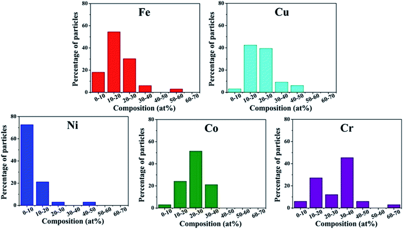 | ||
| Fig. 4 Histogram distribution of Fe, Cu, Ni, Co, Cr elements in HEA NPs synthesized by the mechanical milling technique. Reproduced from ref. 29 with permission from Springer Nature. | ||
2.5 Wet chemical synthesis
Wet chemical synthesis, dealing with chemical reactions in solution, is one of the most frequently used routes to obtain high yields of nanostructured materials. This approach enables fine tuning of the reaction conditions, such as temperature, pressure, and pH, to achieve precise control over the morphology and compositions of NPs, and further their optical, electronic and surface properties. Alloy NPs can be crafted by wet chemical synthesis via co-reduction of metallic ions.30,31 Recently, alloys with compositions of more than five elements have been successfully fabricated under ambient conditions via an ultrasonication-assisted wet chemistry method.32 The ultrasonication can lead to the formation, expansion, and collapse of bubbles in liquid, resulting in a localized hotspot by the conversion of the kinetic energy of the liquid motion.33,34 Under ultrasonication irradiation, Dai et al. successfully synthesized the HEA quinary NPs of PtAuPdRhRu with diameters of less than 3 nm by co-reduction of their corresponding cations at room temperature with ethylene glycol as both the reductant and solvent.32 The HEA-NPs/carbon produced by the ultrasonication-assisted wet chemistry method displays a two-phase microstructure of FCC (Fig. 5).32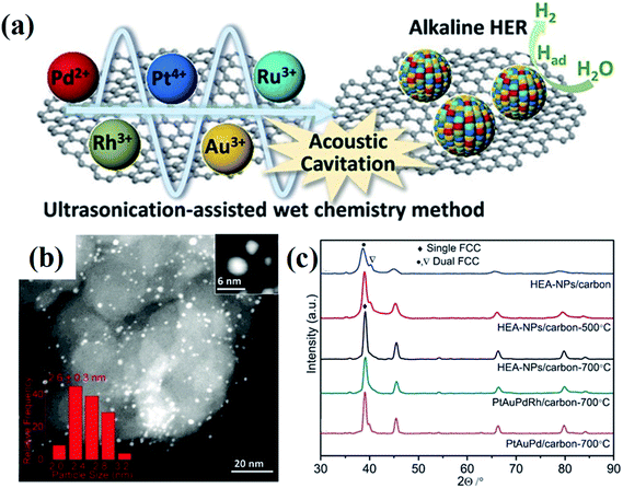 | ||
| Fig. 5 (a) Schematic illustration of the synthesis of PtAuPdRhRu supported on XC-72 carbon and its application in HERs. (b) STEM image of PtAuPdRhRu/XC-72 carbon. (c) XRD patterns of PtAuPdRhRu/carbon synthesized by an ultrasonication-assisted wet chemistry method under different conditions. Reproduced from ref. 32 with permission from John Wiley and Sons. | ||
Notably, the synthesis of HEA NPs by the chemical reduction strategy is challenging, particularly, when the redox potentials of individual components differ substantially. It is prone to yielding alloy NPs with severe phase separation.
2.6 Liquid metal dealloying
Liquid metal dealloying is a general and scalable strategy to prepare ultrafine nano-porous HEAs with enhanced surface areas and uniform pore structures.35,36 In a typical process, HEA nano-structures are prepared by firstly melting pure metals in a furnace in an inert atmosphere. Then the liquid metal is spun to prepare the alloy ribbons, followed by chemical dealloying in an alkaline aqueous solution under sonication. Noble metals such as Ir, Pt, Au, Rh, and Ru are easily obtained by dealloying, whereas some transition metals such as Co, Fe, Ni, Cr, and Mn are prone to oxidation during dealloying.37 Thus, the overall atomic ratio of the active transition metals should be low when using the dealloying strategy to prepare nano-porous HEAs.It has been proven that nano-porous HEAs prepared by the dealloying technique (see Fig. 6) are stable under both annealing and electrochemical cycling conditions due to a thin conformal oxide coating.38,39 Moreover, such a coating improves the catalytic activity of CO oxidation by increasing the efficiency of O2 dissociation which is the rate-limiting step for CO oxidation. Nevertheless, the liquid metal dealloying process for the preparation of the precursor alloy is a high-cost technique due to the requirement of high temperature and an inert atmosphere.
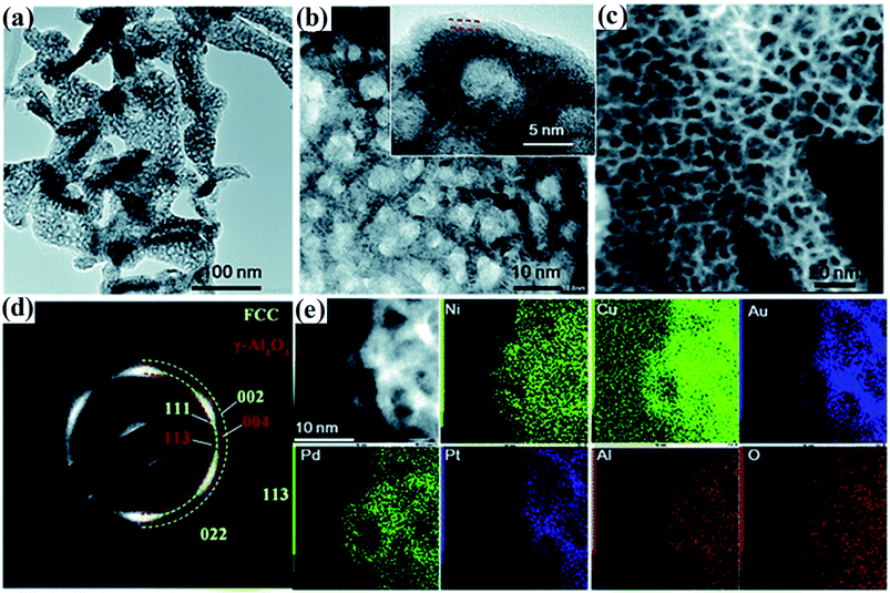 | ||
| Fig. 6 (a and b) TEM images of the dealloyed senary AlNiCuPtPdAu at different magnifications. (c) Dark-field STEM image, (d) the corresponding SAED image and (e) STEM-EDS mapping of AlNiCuPtPdAu. The inset of (b) shows the lattice fringe of the ligaments and the formed thin oxide layer. Reproduced from ref. 38 with permission from the Royal Society of Chemistry. | ||
2.7 Reactive sputter deposition
The reactive sputtering process is used to deposit crystalline multi-element film with controlled reactive magnetron sputter deposition. The technique is based on ion bombardment of the target material to generate vapor via a physical process. The deposition condition is critical to control the grain size, orientation and nanostructures of multi-element films. Therefore, it is feasible to employ the sputter deposition to create HEA NPs for catalytic studies.40 Crafting Pt50Fe11Co10Ni11Cu10Ag8 HEA NPs on noncatalyzed gas diffusion electrodes by the sputter process has been reported.40 Crystalline FCC phases were confirmed by XRD analysis, indicating that annealing treatment is not required to form the solid-solution phase of the HEA NPs. With a calculated deposition rate of 5.2 nm min−1, the sputtering process leads to a distinct morphological evolution during the preparation of a thin layer of HEAs. Increase of the sputtering time coarsened the NPs with larger nodules on the surface. The Pt50Fe11Co10Ni11Cu10Ag8 demonstrated better catalytic ability and stability than the pure Pt in the catalytic reaction of methanol oxidation.40A major drawback of reactive sputtering is its complexity. Some fundamental aspects of the process have not been elucidated yet, which makes it difficult to understand the properties of the obtained HEA NPs as a function of the deposition conditions.
2.8 Pulsed laser ablation
Pulsed laser ablation (PLA) from a solid target emerged as a “green” alternative physical route for a scalable nanofabrication.41 A focused laser used in this technique can induce photothermal effect that rapidly generates a confined high-temperature field at a specific area. It has proven useful for making single nanoparticles42 and even binary alloys.43 Gokce et al. used the PLA method to synthesize CoCrFeNiMn HEA NPs by irradiating a picosecond pulsed laser on the surface of an original ablation target in ethanol solution.44 Although this is an impressive demonstration of synthetic capabilities, corresponding targets are usually required to fabricate the NPs, which greatly limits the technique extension and application. Furthermore, the conventional “planar” geometry of the targets may slow down or stop the nanofabrication process since the laser intensity on the target surface would be gradually weakened with the continuous production of NPs in the system,45 leading to uneven diameter distribution and uncontrolled growth of nanoclusters.Based on the above discussion, we summarize each synthetic strategy in Table 1, including the driving force, experimental conditions, elements contained in HEAs, crystal phase and morphology, substrate applicability, duration time and elemental distribution. Most of the current methods require rigorous conditions including low pressure, temperature and inert atmospheric protection. Under such experimental conditions, HEA NPs are only immobilized on limited thermally resistant substrates (e.g. carbon, γ-Al2O3, zeolite) rather than thermally sensitive ones (e.g. metal foam, glass, polymer, which are often used in many applications). While some synthesis methods, such as electrosynthesis and pulsed laser ablation, yield HEAs under mild conditions, they either require targets with the same composition as the HEA NPs, or only craft amorphous NPs, narrowing the varieties of HEAs. On the other hand, it is clearly found that HEAs with good elemental distribution are generally synthesized in a short period of time, even microseconds. It is understandable that the high mixing entropy property of HEAs contributes to solid solution formation at high temperatures due to TΔSmix. In the slow cooling process, segregation or precipitation of the second phase may occur due to decreased TΔSmix, thus forming heterogeneous microstructures. A faster cooling rate can suppress the formation of secondary phases, and tend to create single-phase HEAs with good elemental distribution.
| Strategy | Driving force | Experimental conditions | Elements | Structure | Substrate applicability | Duration time | Elemental distribution | Ref. |
|---|---|---|---|---|---|---|---|---|
| Carbothermal shock | Electrically triggered Joule heating | 2000 K, argon | Pt, Pd, Co, Ni, Fe, Au, Cu, Sn | FCC, NPs | Carbon substrates | 55 ms | Good | 18 |
| Electrosynthesis | Electro-shock | RT, air | Pt, La, Co, Cr, Cu, Gd, In, Mn, Ni, V | Amorphous, NPs | Graphite | 100 ms | Good | 6 |
| Moving bed pyrolysis | Pyrolysis | 923 K, argon | Pt, Au, Ir, Sn, Pd, Rh, Cu, Ni, Co, Mn | FCC, NPs | Carbon, Al2O3, zeolite | 5 s | Good | 24 |
| Solvothermal pyrolysis | Pyrolysis | 700 K, argon | Mn, Fe, Co, Ni, Cu | FCC, NPs | Carbon cloth | >5 h | Poor | 21 |
| Mechanical milling | Mechanical force | RT, air | Ni, Cr, Co, Cu, Fe | FCC, NPs | Graphene | >80 h | Poor | 29 |
| Wet chemistry | Ultrasonication & reduction | 973 K, nitrogen | Pt, Au, Pd, Rh, Ru | FCC, NPs | Carbon | >5 h | Poor | 32 |
| Liquid metal dealloying | Heat & chemical reaction | >873 K, argon | Al, Ni, Cu, Pt, Pd, Au, Co, Fe, Mo | FCC, nanoporous | W/O | >5 h | Poor | 38 |
| Reaction sputter deposition | Magnetron sputtering | 5 × 10⁻⁶ torr | Pt, Fe, Co, Ni, Cu, Ag | FCC, NPs | Gas diffusion electrodes | >25 h | Poor | 40 |
| Pulsed laser ablation | Pulsed laser | RT, air | Co, Cr, Fe, Ni, Mn | FCC, NPs | W/O | ∼ms | Good | 44 |
3. Core effects of HEAs
The multi-elemental character of HEAs leads to some important effects that are much less pronounced in conventional alloys.46 Among these, four core effects including high entropy, cocktail, sluggish diffusion and lattice distortion are more basic.47 This section will briefly introduce the core effects as well as their impact on the catalytic properties of HEAs.3.1 High entropy effect
Based on Boltzmann's hypothesis, the configurational mixing entropy (ΔSmix) can be expressed as:48where n is the number of principal elements, R is the gas constant, and ci is the mole fraction of component i. The relationship between the ΔSmix value and the number of principal elements mixed in equimolar ratio is shown in Fig. 7a and b. In a broad sense, 1.5R is used as a border line between HEAs and medium-entropy alloys.49 Since the growth rate of ΔSmix slows down after a 9-element alloy, HEAs with 5 to 9 components are suggested in practical application.49,50 More components will not benefit from high entropy but increase the material complexity.
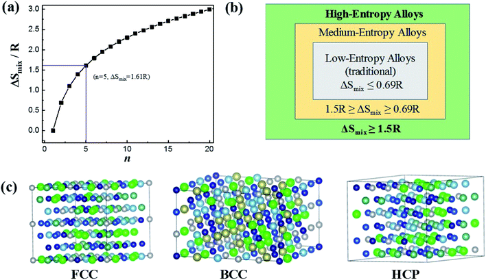 | ||
| Fig. 7 (a) ΔSmix as a function of the number of principal components for equimolar alloys. (b) Alloy definitions based on configurational entropy. (c) Structural illustration for the FCC, BCC and HCP phases of HEAs. Reproduced from ref. 51 with permission from Frontiers. | ||
The characteristic of high mixing entropy enhances the mutual solubility among elements and facilitates the formation of simple FCC, BCC or HCP solid solution phases within HEAs during solidification (Fig. 7c).50 Cantor et al. manufactured transition-metal-rich HEAs with six to nine components (the same five elements of Fe, Co, Ni, Cr, and Mn together with other elements such as Cu, Ti, Nb, Ni, Mo, Ta and Ge) in equal atomic ratio, which also forms a single FCC solid solution.52
In principle, HEAs with a solid solution phase have many merits that can justify them as great potential catalysts. Firstly, they can be produced with wide composition ranges not available in the crystalline form, permitting the fine tuning of their electronic properties to meet catalytic reaction demands.53 Under the definition of HEAs which consist of more than five elements, we can obtain a total of 7099 possibilities for designing equal-mole HEA systems at an arbitrary choice of a group of 13 metallic elements.49 Unequal-mole HEAs may also be designed with minor alloying elements like AlCo0.5CrCuFe1.5Ni1.2B0.1C0.15 for further modification of the microstructure and electronic properties. As a result, HEAs offer researchers even more room for design in terms of their composition and electronic properties than traditional alloys. Secondly, the isotropic and homogeneous characters of the alloys allow the active sites in a chemically identical environment. For HEAs, their single-phase character and lack of surface segregation of the alloying elements ensure that the catalytically active species are dispersed uniformly, which would benefit the development of the HEA catalysts with high and exclusive selectivity.54 Thirdly, the high entropy effect has been considered to be the main reason for the stability of HEAs. The increase of the number of components significantly increases the configurational entropy, and leads to phase stability via a decrease of the Gibbs free energy.3 It has been reported that the HCP phase of HEA catalysts (IrOsReRhRu) is still retained after heat treatment up to 1500 K and compression to 45 GPa, achieving a record temperature and pressure stability for a single-phase HEA.55 Due to the large difference in compressibility between Os and other metals, the HEA has higher thermal expansion and lower bulk modulus in comparison with the pure metals in the compositions.55 In the electrocatalytic oxidation of methanol, the simple-phase character and the high mixing entropy of the elements in HEAs ensure that the active sites are in a uniform dispersion in a homogeneously chemical environment, thus showing pronounced electrocatalytic activity.55 In the nanostructures of HEA-CoMoFeNiCu, the five principal components are initially randomly assigned to each lattice site, forming a simple FCC phase. Such a solute–solution mixing phase prevents a large miscibility gap which presents in a bimetallic Co–Mo alloy.56 As shown in Fig. 8, the randomly mixing surface with uniform distribution of Co and Mo sites optimizes both the dehydrogenation of NH3 molecules and the desorption of the product N2 from the HEA surface in the catalytic decomposition reaction of NH3.56
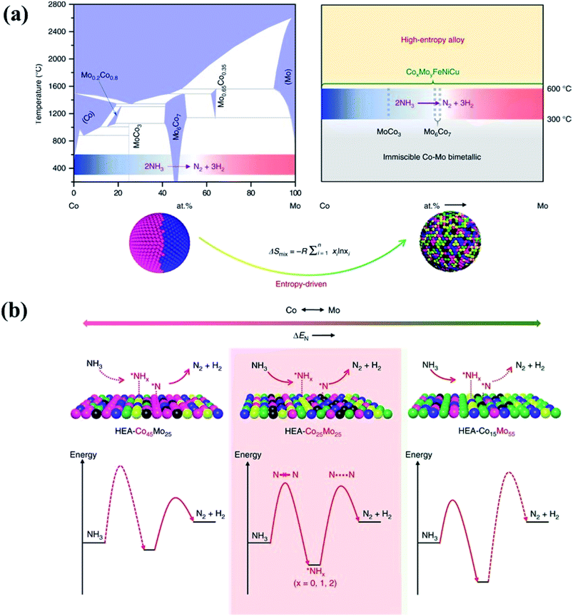 | ||
| Fig. 8 (a) HEA catalysts preventing a large miscibility gap which presents in conventional binary alloys. (b) Schematic illustration of the rate-limiting factors in NH3 decomposition, labeled with dash lines in the lower panel. On a Co-rich surface (left), the rate is limited by activation or dehydrogenation of NH3; on a Mo-rich surface (right), the rate is limited by the recombinative desorption of *N; the balance for these two steps is reached on an intermediate composition with uniform distribution of Co and Mo atoms. Reproduced from ref. 56 with permission from Springer Nature. | ||
3.2 Cocktail effect
HEAs can be considered as composite materials at the atomic scale due to their multi-elemental character. Their properties are certainly related to not only the properties of the individual composing principal elements, but the interaction among the elements. In other words, some unexpected properties may be obtained after mixing many elements, which would not manifest using any one independent element. For example, although Al is a soft and low-melting-point element, the addition of Al can dramatically harden CoCrCuNiAl HEAs due to the formation of a hard BCC phase as well as the stronger cohesive bonding between Al and other elements.3,57,58 This phenomenon is called the “cocktail effect”, which was first mentioned by Ranganathan59 and then confirmed via the mechanical properties.60–62The multi-metallic cocktail effect can optimize the electronic structures of catalysts. In HEA systems containing Ni and Pd, the electron transfer from Ni to Pd could occur due to the smaller electronegativity of Ni than Pd, which can decrease the Pd–CO binding energy and enhance the catalytic oxidation of methanol molecules.63 Moreover, the electronic states of metal atoms are altered by alloying with the d-band center of Pd shifting down and the d-band center of Ni shifting up, promoting the electrocatalytic activity of Pd towards methanol/ethanol oxidation and enhancing the adsorption of adsorbates on the Ni sites.64 The cocktail effect can also alter the charge transfer and chemical ordering of HEAs, as shown in Fig. 9. In an AlCoCrCuFeNi HEA, the occupied and empty Ni 3d states shift away from the Fermi level, whereas the Cr 3d empty states shift towards the Fermi level, compared to the corresponding pure metals.65 The charge transfer between the elements in HEAs is negligible due to the compensation of the 3d state occupancy change by the redistribution of delocalized 4s and 4p states of the transition metals.65 These properties play important roles in the optimization of the adsorption energy of HEAs during catalytic reactions.
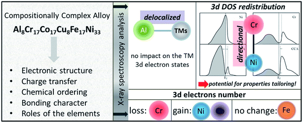 | ||
| Fig. 9 The altered properties of HEAs as compared to the corresponding pure metals. A proposed scheme for the DOS redistribution of the Ni and Cr 3d bands occurring upon formation of the AlCoCrCuFeNi HEA. Reproduced from ref. 65 with permission from Elsevier. | ||
In a word, the cocktail effect in HEAs is generally considered as a complex synergetic mechanism that is responsible for the outstanding catalytic performance of HEAs. The synergistic interactions of the multi-element compositions in HEAs have resulted in a huge divergence of the properties as compared to atoms in single-element metals. But the remarkable thing is that the mechanism of action of such multi-component synergy in HEAs remains largely unknown. The underlying synergistic mechanisms from the view point of lattice distance and electron distribution should be further explored.
3.3 Sluggish diffusion effect
Diffusion refers to the phenomenon wherein atoms vibrating at the lattice equilibrium absorb energy at high temperatures and migrate away from their original positions. In phase transformations controlled by diffusion, the formation of a new phase usually requires the cooperative diffusion of elements to attain the equilibrium partition among the phases. Each principal component in HEAs usually presents a highly chaotic state due to the high entropy of the mixing effect. The principal atoms in HEAs can be regarded as either solute or solvent atoms, which increase the resistance of atomic diffusion and reduce the atomic diffusion rate. The phase separation is inhibited, and the nucleation and growth of new phases are suppressed. This phenomenon is known as the sluggish diffusion effect on the kinetics of HEAs.The sluggish diffusion effect of HEAs can suppress the degradation caused by the coarsening of nanostructured HEA catalysts.35,66 Despite the poor corrosion resistance of pure transition metals in strong acid or alkali solution, the high entropy alloy Ni20Fe20Mo10Co35Cr15 composed of such elements showed high corrosion resistance in both acidic and basic electrolytes for the hydrogen evolution reaction (HER).66 The reasons for the sluggish diffusion effect of HEAs are still controversial. Most of the researchers hold the view that multiple components are responsible for the sluggish diffusion due to low lattice-potential-energy sites provided by small atoms.35,67 HEAs with multiple principal elements have larger fluctuations in lattice potential energy than pure metals or traditional alloys (Fig. 10). Many low lattice-potential-energy sites always serve as atomic traps and blocks.67 Thus, if an atom jumps to a low-local-potential state, it would have a low possibility to jump out. In contrast, if an atom jumps to a high-local-potential state, it would have a high chance to hop back to the initial site. Both cases can hinder atomic diffusion and particle coarsening due to the increased energy barrier and activation energy for diffusion. Meanwhile, some other researchers think that certain elements, such as Mn in CoCrFeMnNi alloy, produce a deep potential wall and thus cause a sluggish effect.67 Therefore, a thorough study should be performed to clarify the origins of the sluggish diffusion effect of HEAs, which in turn helps researchers better design the overall architecture of high-performance HEA catalysts.
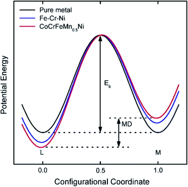 | ||
| Fig. 10 Schematic diagram of the variation of low-potential energy and mean difference (MD) during the migration of a Ni atom in different matrices. The MD for pure metals is 0, whereas that for HEA is the largest.67 Reproduced from ref. 67 with permission from Elsevier. | ||
3.4 Lattice distortion effect
HEAs are composed of various elements with different sizes, leading to the lattice distortion effect (Fig. 11a and b).68 Larger atoms tend to push away their neighbors to occupy more space, whereas small ones are distributed in extra space. The large atoms lead to compression, whereas small ones result in tension strain in the lattice. The bonding energy between atoms is another factor that causes the lattice distortion. Stronger bonds are prone to have smaller bonding distances than weaker bonds. The lattice distortion effect in HEAs is claimed to be more severe than in conventional alloys. If the differences in the properties and structures of the principal elements are large enough, the distortion of the material system will be too severe to maintain the original stable lattice, and the collapse will occur to form an amorphous structure. The lattice distortion effect can affect the mechanical, chemical and physical properties of HEAs.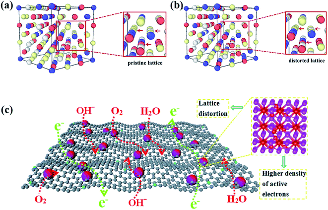 | ||
| Fig. 11 The DFT simulation results of (a) the pristine lattice with an ideal FCC structure and (b) the distorted lattice of the CoCrFeNi alloy. Reproduced from ref. 68 with permission from Frontiers. (c) Schematic of the advantages of the lattice-distortion alloys for bifunctional oxygen electrocatalysts.69 Reproduced from ref. 69 with permission from Elsevier. | ||
It was reported that the lattice distortion in an Fe-enriched alloy promoted a higher density of active electrons around the Fermi level (Fig. 11c).69 The higher density of activated electrons results in faster electron transfer. In contrast, the electron transfer in alloys with a pristine lattice is quite limited due to the absence of activated electrons. Thus, the alloys with lattice distortion showed improved catalytic performance than alloys with a pristine lattice in catalysis, such as the oxygen evolution reaction (OER) and oxygen reduction reaction (ORR).69 Moreover, some metastable structures (namely fragmented domains such as short-range order, critical defects, amorphous structures, etc.) may form to accommodate the lattice distortion effect during the preparation of HEAs.1 Such metastable microstructures are believed to play a key role in enhancing the catalytic performance of HEAs. Lattice distortion can also induce a residual strain field with atomic scale fluctuation, shift the d-band center of catalysts and ultimately affect the catalytic selectivity. The effects of these microstructures and strain on the catalytic performance of HEA catalysts are discussed in detail in Section 3.2 and 3.3, respectively.
In brief, the high-entropy effect simplifies the microstructures of HEAs to form simple solid solution phases, leading to the homogeneous distribution of active site configurations in catalysis. The cocktail effect causes a synthetic effect on properties, wherein the interactions among the different elements may optimize the adsorption energy of the intermediates, thereby enhancing the catalytic activity. The sluggish diffusion effect increases the activation energy and reduces the coarsening kinetics in the grain growth process. It enhances the thermal and chemical stability of HEAs in catalysis. The lattice distortion effect has a great impact on the physical and chemical properties of HEAs, which often results in severe strain due to the atomic size mismatch. Such a strain potentially shifts the d-band center of alloys, and affects the binding modes of intermediates as well as the catalytic selectivity. Moreover, some possible metastable microstructures in the solid-state solution phase of HEAs may form during the preparation process due to the lattice distortion effect, which holds promise for providing a variety of active sites in catalysis.
4. Core effect-induced properties for highly efficient HEA catalysts
The four core effects, discussed in Chapter 3, play crucial roles in determining the properties of HEAs such as metastable microstructures, strain, ligand and ensemble effects, d-band center, and adsorption energy. Microstructures of HEAs (e.g. amorphous/intermetallic precipitates, short-range orders, vacancies, grain boundaries) induce strain, ligand and ensemble effects which then affect the position of the catalyst d-band center. The d-band shift has a significant impact on the optimization of the adsorption energy of the reactants, which is responsible for the high catalytic activity of various reactions. To date, HEA catalysts have been involved in reactions including electrocatalysis (i.e. methanol and CO oxidation, CO2 reduction, HER, OER and ORR), thermocatalysis (i.e. NH3 decomposition and NH3 oxidation), and catalytic degradation of azo-dyes at room temperature. These catalytic applications of HEAs and the mechanisms for the improved performance have been summarized in Table 2. This chapter mainly discusses the relationship between these properties of HEAs in detail as well as their impacts on the catalytic performance of catalysts in these reactions.| HEAs | Phase | Synthetic method | Reaction | Mechanisms for improved performance | Ref. |
|---|---|---|---|---|---|
| PtFeCoNiCuAg | FCC | Sputter | Electrocatalytic methanol oxidation | Not mentioned | 70 |
| PtNiCoCuFe | Not mentioned | Electrosynthesis | Electrocatalytic methanol oxidation | Resistance to the poisoning of carbonaceous species | 71 |
| IrOsReRhRu | HCP | Pyrolysis | Electrocatalytic methanol oxidation | Not mentioned | 55 |
| NiNbPtSnRu | Amorphous | Mechanical milling | Electrocatalytic methanol and CO oxidation | Lower rate of poisoning | 72 |
| PtRuCoOsIr | FCC + HCP | Dealloying | Electrocatalytic methanol oxidation and the ORR | The downshift of the Pt d-band weakens the O–O bond | 73 |
| AlCoCrTiZn | BCC | Mechanical milling | Catalytic degradation of azo-dyes | Lattice distortion and residual stress lead to a low activation energy barrier | 74 |
| AlCrFeMnTi | FCC + BCC | Mechanical milling | Catalytic degradation of azo-dyes | The presence of plenty of nano-galvanic cells among the principal elements | 75 |
| AuAgPtPdCu | FCC | Mechanical milling | Electrocatalytic CO2 reduction | Destabilization of *OCH3 intermediates and the strong stabilization of *O intermediates | 9 |
| NiFeMoCoCr | FCC or FCC + μ | Arc-melting | Electrocatalytic HER | High coordination numbers of single-phase FCC promote the hydrogen adsorption | 66 |
| FeCoPdIrPt | FCC | Moving bed pyrolysis | Electrocatalytic HER | The downshift of Pt antibonding states facilitates hydrogen species desorption | 24 |
| IrPdPtRhRu | FCC | Polyol method | Electrocatalytic HER | Deeper d-band centre locations (between Ir and Pt) | 76 |
| MnFeCoNiCu | FCC | Solvothermal-pyrolysis | Electrocatalytic OER | The presence of lattice defects contributes to the catalytic activity | 21 |
| AlNiCoFeX (X = Mo, Nb, Cr) | FCC | Top-down synthesis | Electrocatalytic OER | X atoms prefer high formal oxidation states, facilitating proton migration to O at Ni/Co sites | 77 |
| CoFeLaNiPt | Amorphous | Electrosynthesis | Electrocatalytic HER and OER | Synergism between Pt and the other elemental components on the atomic scale | 6 |
| PtAuPdRhRu | FCC | Wet chemistry | Electrocatalytic HER and OER | High-entropy at the nanoscale and strong synergistic effects between active metals | 32 |
| AlNiCoIrMo | FCC | Dealloying | Electrocatalytic HER and OER | The increased covalency of Ir–O bonds by alloying | 36 |
| CrMnFeCoNiNb | Not mentioned | Sputter | Electrocatalytic ORR | Solid solution phase with altered properties overcomes the limitations of the single elements | 78 |
| AlCuNiPtMn | FCC | Dealloying | Electrocatalytic ORR | The best electronic modulation for the Pt surface through surface strain and/or ligand effects | 79 |
| PtPdFeCoNi | FCC | Carbothermal shock | Electrocatalytic ORR | Rapid electrochemical screening is demonstrated by using a scanning droplet cell | 80 |
| Hollow RuIrFeCoNi | FCC | Droplet-to-particle | As the cathode catalyst for Li–O2 batteries | Maximizing the material usage efficiency by tuning the HEA shell thickness | 2 |
| FeCoNiCuMo | FCC | Carbothermal shock | Thermocatalytic NH3 decomposition | Tunable surface adsorption properties by varying the Co/Mo ratio | 56 |
| RuRhCoNiIr | FCC | Carbothermal shock | Thermocatalytic NH3 decomposition | A synergistic effect from multiple elements, ultrafine size, and homogeneous structure | 1 |
| PtPdRhRuCe | FCC | Carbothermal shock | Thermocatalytic NH3 oxidation | Homogeneous nature of the solid-solution NPs | 18 |
4.1 Metastable microstructures
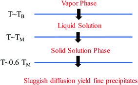
It should be clarified that mixing entropy is generally compared in the random solid-solution state or liquid solution. Compared with conventional alloys, HEAs have high mixing entropies in these states. The solidification process determines the microstructure formation of HEAs. Fig. 12 shows the phase transformation during the solidification of an HEA.49 The high mixing entropy effect of HEAs facilitates the formation of the solid solution phase at high temperature due to TΔSmix. During subsequent cooling, segregation or precipitation of the second phase may occur because mixing entropy becomes less important. However, the sluggish diffusion effect of HEAs leads to the production of fine microstructures. A faster cooling rate can suppress the precipitation of the second phase to form the solid-solution or amorphous phase, whereas a slower cooling rate would create intermetallic phases. Because the high configurational entropy effect is often insufficient to fully stabilize a single-phase solid solution in the presence of lattice strain enthalpies or structural mismatch of components, metastable microstructures, such as amorphous/intermetallic precipitates, short-range orders, vacancies, and grain boundaries, are inevitably formed during the preparation of HEAs.81,82 These fine metastable microstructures disrupt the local chemistry and cause heterogeneity in HEAs. The types and density of the microstructures are closely related to the synthetic techniques.An interesting issue arises regarding the functions of the metastable microstructures in catalytic reactions. Alloys with these microstructures have coordinatively unsaturated sites which are essential for the bonding and activation of the reactants. HEAs have a high concentration of coordinatively unsaturated metal centers (active sites), which makes adsorption83 and surface reactions84 easier than on the corresponding crystalline catalysts. Although the effect of such microstructures on the catalytic properties of HEAs has not yet been reported in the literature, their functions in traditional metal/alloy-based catalysts have been demonstrated in detail.85–87 It has been reported that the presence of unsaturated Ni(II) binding sites in a nano-porous hybrid material significantly improved hydrogen sorption quantity compared with that of similar materials without unsaturated metals sites.83 A silver catalyst with stacking faults (defects) and a low coordination number showed superior activity of the hydrogen evolution reaction that outperforms commercial platinum on carbon which is usually considered as the best catalyst.88 These sites make the adsorption and surface reactions of catalytic intermediates easier than conventional crystalline catalysts, ensuring a high catalytic activity. Catalytic doping of alloys is an effective avenue to improve the hydrogen-storage property of MgH2. Compared with crystalline HEAs, amorphous counterparts exhibited better kinetics and lower activation energies during MgH2 catalysis due to a more uniform distribution of highly refined nanostructures in the amorphous phase.77 The amorphous alloy catalysts become brittle by absorbing hydrogen, which is beneficial to the formation of refined nanostructures. Consequently, the presence of an amorphous HEA catalyst with the refined nanostructures accelerates hydrogen diffusion in the Mg/MgH2 matrix, thus enhancing the hydrogen storage properties of MgH2. In addition, as the metastable structures are nonporous, the surface reaction would not be affected by diffusion limitations, which is often a problem in traditional heterogeneous catalysis.89 All these features make HEAs with metastable microstructures attractive in heterogeneous catalysis.
4.2 Relationships of strain, ligand and ensemble effects with the d-band of HEAs
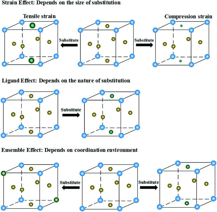
The presence of the metastable microstructures can affect the lattice constant (strain effect), spatial arrangement of different elements (ligand effect), and alloy geometries (coordination effect).90 These three effects are considered to tune alloy surface properties and play significant roles in the improvement of catalyst activity. As shown in Fig. 13, the strain effect depends on the size of the substituted atom, the ligand effect relies on the nature of the substitution, and the ensemble effect is related to the coordination environment of atoms. This section describes the three effects in detail, and their relationships with the HEA d-band are also discussed.The mechanical behavior of catalysts is one of the most important factors for the reliable and efficient catalytic reactions, and understanding the role of surface strain in tuning the reaction is critical for catalyst design.92–97 For instance, as-exfoliated monolayered WS2 nanosheets exhibited enhanced electrocatalytic activity for hydrogen evolution due to the high concentration of the strained metallic 1T phase.98 In principle, strain modifies the physical/chemical properties of catalyst surfaces by changing the average energy of the d band.99 The width of the surface d band was found to be proportional to the interatomic matrix element that describes bonding interactions. The misfit strain changes the width of the d band through changes in the d-orbital interactions between the d orbitals of a metal atom and the d orbitals of its nearest neighbors that are quite sensitive to interatomic spacing.100 As a consequence of the d width change, the average energy of the d band (the d-band center) moves down or up relative to the Fermi energy in order to maintain a constant d-band filling, resulting in modifications of the strained surface properties. On the basis of the theoretical simulations, the d-band center of catalysts play an important role in their catalytic activity because the d-orbital electrons determine both bond formation and breaking of the intermediate species.101,102 According to the d-band model,103 the position of the d-band center determines the adsorption energies and activation energy barriers. The shift of the d-band center influences the bonding and anti-bonding states of adsorbates and reactants on the alloy catalyst surface, and further determines the activity and selectivity of catalytic reactions.104 To achieve optimal catalytic activity, the d-band center must not be too close or too far from the Fermi level. Notably, the shift trend of the d-band center is reverse for late transition metals (LTMs, for which the d bands are more than half filled) and early transition metals (ETMs) with a less than half-filled d band. Fig. 14 shows the influence of tensile strain on the position of the d band in ETMs and LTMs.105 ETMs exhibited lower adsorption energies under tensile strain because the expanded lattice reduced the overlap of the wavefunctions and therefore narrowed the metal d band, in contrast to what is observed in LTMs.105,106 The band narrowing results in an increased population of the d band of LTMs, upshifting the d-band center to preserve the degree of d-band filling. Yan et al. proved that the influence of externally applied elastic strain on the catalytic activity of metal films in the hydrogen evolution reaction (HER) is in a controlled and predictable way.107 The activities of Ni and Pt were accelerated by compression, while that of Cu was accelerated by tension.107 Pt-based catalysts exhibited intensive adsorption for catalytic intermediates in the HER and ORR, which was weakened by introducing compressive strain through interface mismatch or size reduction.108–111 It has been reported that a surface strain of −2.0% would be the best for Pt-based alloy catalysts toward the highest ORR activity.112,113 DFT has proven that a Pt layer with −2.0% strain would lead to 30 times higher ORR activity than pure Pt.114 In the experiment, the 3ML-Pt/Pt25Ni75(111) alloy with −1.7% strain (close to the best strain of −0.2% in theoretical predictions) displayed enhanced activities for the ORR, consistent with the theoretical results.83 For the FeCoPdIrPt system in the HER,24 Fe, Co and Pd could downshift the d-band center of Pt, and more electrons could occupy the antibonding states, facilitating the desorption of hydrogen species to produce more hydrogen than the commercial Pt/C catalyst.
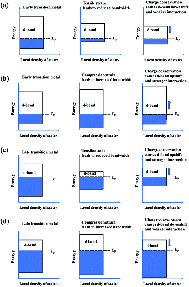 | ||
| Fig. 14 The effect of (a and c) tensile and (b and d) compression strain on the position of the d band in early transition metals and late transition metals. | ||
Considering that catalytic materials are usually nanoscale and the absolute magnitude of the induced strain is very small, strain along a certain direction is defined as (lf − li)/li, where li and lf represent the atomic bond length in the initial and final states, respectively.105 It has been proven that the maximum catalytic activity required an optimum atomic bond length in catalysts.115 A larger atomic bond length would cause oxygen dissociation before the adsorption in ORRs, whereas a smaller value would generate strong repulsive forces for dual-site adsorption.115 Furthermore, an optimized surface strain can contribute to a high HER performance due to the small hydrogen adsorption Gibbs free energy on the catalytic sites.116 Strain-induced changes in the atomic bond length can be viewed as the bulk lattice distortions in catalysts.105 For HEAs, a serious lattice distortion effect gives rise to changes in the surface strain. The surface strain of HEAs can be tuned by selecting principal components with different atom radii. A seven-component FeNiCoSiCrAlTi HEA coating with BCC solid solution phase was prepared by laser cladding on a low carbon steel substrate.117 The presence of the small-atomic-radius Si and large-atomic-radius Al and Ti increased the lattice packing density and crystal distortion. The segregation of Ti atom caused the different lattice expansion and growth stress between Ti-depleted polygonal grains and Ti-enriched interdendrites, which can lead to increase of the contraction stress at their interfaces.117 A higher concentration of Al, which has a larger atomic radius than Co, Ni, Fe, and Cu elements, resulted in a larger lattice distortion of Co25Ni25Fe25Al7.5Cu17.5 with transformation of the HEA phase from FCC into a BCC structure.118–120 This result revealed that the distribution of random elements with various atomic radii in HEAs can induce volume contraction or expansion along the specific direction. In addition, the local lattice distortion can result in the fluctuation of stacking fault (SF) energy.121,122 The SF energy can change the number of SFs in catalysts, and thus tune their catalytic properties.16 A high density of SFs in silver NPs caused a low coordination number and high tensile strain, transforming the non-active Ag into a highly active catalyst towards the HER.116 The different atomic radii of the principal elements in HEAs can induce local strain effects due to the variation of SF energy.34 SF–SF intersections produced a local strain field, leading to dislocation accumulation and SF formation in order to release the local strain concentration.34 Based on the above mentioned analysis, it is expected that HEAs can optimize the surface strain, surface d-band width and SF density by selecting principal components with different atomic radii to achieve high catalytic activity.123
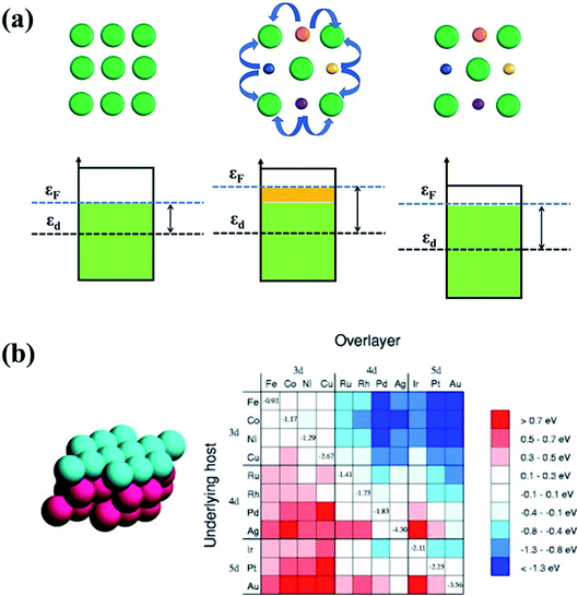 | ||
| Fig. 15 (a) The ligand effect of HEAs and the d-band center shift. The green balls represent noble metal atoms. The orange, purple, blue and yellow balls represent non-noble metal atoms. (b) Changes in the d-band centers for monolayer overlayer on transition metal substrates. Reproduced from ref. 125 with permission from Elsevier. | ||
Owing to the ligand effect, the reactivity of one metal can be varied substantially by depositing it on another due to the adjustment of the d-band. Fig. 15b displays the d-band center change of a given metal when it is deposited on another metal, calculated by DFT.125 This helps us to design HEAs with suitable components for a specific catalytic reaction. For instance, Pt is generally used as an anode catalyst for PEM fuel cells. However, the strong binding of CO on the Pt surface leads to poisoning of the catalyst. Finding a catalyst surface that weakly binds CO is desirable. As shown in Fig. 15b, a surface with weaker CO bonds than Pt(111) can be obtained by positioning Pt on top of atoms such as Ir, Rh, Ru, Cu, Fe, and Co, due to the down-shift of the Pt d-band.125 Likewise, if a surface with stronger adsorption energy of intermediates is required, Pt can be put on atoms such as Ag or Au to up-shift the d-band center.
As lattice strain often changes the electronic structure of alloys, the strain effect and the ligand effect are difficult to be distinguished in practical HEA catalysts. To understand the contribution of the ligand effect, Rossmeisl et al. have isolated the electronic ligand effect of the HEA catalyst (IrPdPtRhRu) from the strain effect by creating an unstrained environment in DFT to investigate its ORR activity (Fig. 16).126 After statistical analysis of 2000 DFT calculations and subsequent host/guest calculations, it has been found that selected atoms among the fourth nearest neighboring positions in the third layer of an FCC (111) metallic structure have more impact on the bond strength of an adsorbate in the ORR than any second or third nearest atomic positions.126 It is found that the ligand effect affects both the d-band center and d-band shape which correlates closely with the bond strength of the adsorbate.
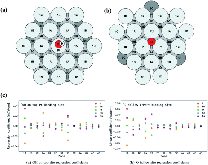 | ||
| Fig. 16 Schematic of atomic positions grouped by layer and distance from the binding site on an FCC (111) surface microstructure for (a) on-top adsorption on Pt and (b) fcc hollow site adsorption on IrPdPt. The fourth layer contains zones 4A, 4B, 4C and 4D and has an identical layout to the first layer. (c) Overview of the regression coefficients of the least squares fits for each element by zone. The atoms with direct coordination (i.e., zones 1A and 2A) to the binding atoms have a large effect on the binding energy of the intermediate. Zone 3B has a similar sized impact on the binding energy to the neighbors in zone 2A. Reproduced from ref. 126 with permission from John Wiley and Sons. | ||
Alloys with distinct atomic ensembles result in different absorber binding strengths. When Au alloys with Pt as the catalyst in allyl alcohol hydrogenation, the H atoms are only adsorbed onto Pt sites.127 Au atoms, which simply act as a surface diluent, have no impact on the H binding energy. PtAu catalysts exhibit a linear increase in activity with increasing Pt ratios.127 However, when Pt atoms are replaced by Pd, H can interact with both Pd and Au atoms. Thus, the binding energy strength of H atoms on the Pd–Au atomic surface ensemble can be tuned to achieve improved hydrogenation activity. The contrasting behavior of PtAu and PdAu alloys is because different effects work in these two systems. The ensemble effect dominates the PtAu system, whereas PdAu alloys exhibit both ensemble and ligand effects. The ligand effect results in the direct charge transfer from Au to Pd atoms, leading to the d-band perturbation. These results provide valuable guidance for tuning the absorber binding energy by screening suitable components in HEAs.
Overall, the strain, ligand, ensemble effects and the d-band perturbation can significantly affect the adsorption energy of intermediates in catalytic reactions. The following section mainly discusses the relationship between the adsorption energy and catalytic activity of HEA catalysts.
4.3 Adsorption energy
A typical catalytic process usually involves the adsorption of reactants on catalysts, and chemical bond-breaking/formation between the catalyst and the reactants to generate activated intermediates.128 The adsorption energy of the intermediates is the most important factor that determines the rate and selectivity of products in catalytic reactions because the catalytic activity is attributed to the interfacial electronic coupling.128,129 According to the Sabatier principle, the measured activities as a function of the binding strength are plotted in a volcano curve.94–96,130 It indicates that either too strong or too weak binding strength to the intermediates causes difficulty in removing the products or poor adsorption of the reactants, respectively.97 The binding strength of catalysts is closely related to their structural properties. It is crucial to design catalysts with moderate binding strength.131 Compared with the low intrinsic activity of the binary systems, which is related to the position of their elements in volcano plots, the HEA catalysts show enhanced activity due to the broad adsorption energy distribution easily covering favorable energies.132 The cocktail effect of HEA catalysts can facilitate hybrid chemical and electronic interactions between metal components, thus affecting the adsorption energy of intermediates during catalytic reactions. For example, an alloying metal of Ir0.19Os0.22Re0.21Rh0.20Ru0.19 with the HCP phase has been found to weaken the adsorption of CO in methanol oxidation due to the optimized electronic structures of the HEA catalyst, making CO easier to be removed.55 The HEA alloy displayed higher yield and selectivity of CO in the methanol oxidation reaction than individual metals.55 Schuhmann et al. discussed the effect of different adsorption energy distribution patterns on the activity curves of catalytic reactions by analyzing the experimental activity curves.132 The number of adsorption peaks is the same as that of elements in HEAs. Each adsorption peak for HEAs contributes one exponentially increasing current curve of different activities governed by the position of the peak maximum regarding optimal binding energies.132Fig. 17a illustrates active site distribution within one adsorption peak. The model is simplified by reducing the number of active sites to 7. Active site 7 has the highest activity whereas active site 6 shows the least favorable binding energy.132 In Fig. 17b, seven individual curves sum up to the overall measured curve, the activity of which is governed by the relative position of the respective peak maximum regarding optimal binding energies. To achieve high activity, a good fit of the best adsorption peak maximum with the optimal binding energy is required.132 The position of the peaks in adsorption energy distribution patterns directly determines the shape of the catalytic curves. As shown in Fig. 17c, an overlap of the three most active peaks in the six-element CSS #6_2 causes difficult separation of all three wave segments in a catalytic curve.132 In the case of the five-element CSS #5_2 with replaced elements, the third most active peak in the adsorption energy distribution pattern shifted towards unfavorable binding energies, resulting in only two wave segments within the considered regime. By comparison, the six-element CSS #6_1 shows the best peak.132 Thus, the change in energy of the adsorption peaks on replacement or addition of elements is determined by the inherent properties of the material.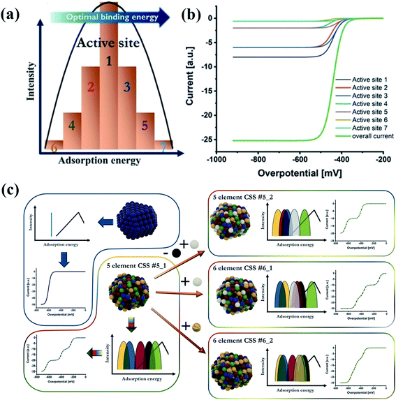 | ||
| Fig. 17 (a) Scheme of active site distribution within one adsorption peak. (b) Visualized intrinsic current response in the kinetic region of these grouped active sites, considering their activity as well as the intensity. (c) Scheme of correlations between a complex solid solution (CSS) NP structure, its effect on the adsorption energy distribution pattern, and the respective electrochemical response in the kinetic region. Reproduced from ref. 132 with permission from John Wiley and Sons. | ||
The optimization of adsorption energy has also been found when a nanocrystalline AuAgPtPdCu HEA was used for the electrocatalytic reduction of CO2.9 The faradaic efficiency is near 100% with respect to gaseous products at −0.3 V vs. reversible hydrogen electrode (RHE) due to a large number of catalytic sites present randomly on the surface of the HEA NPs, highlighting the uniqueness of the HEAs.9 In CO2 reduction, the conversion of *OCH3 into the *O intermediate, which is an endoergic reaction, has been considered the rate-determining step due to the high barrier. DFT calculation, based on the free-energy calculations of intermediates, demonstrated that the barrier is much lower for the HEA system (1.35 eV) than for the pristine Cu(111) (1.95 eV), as shown in Fig. 18.9 The fact that the CO2 reduction on the HEA NPs over the Cu(111) is thermodynamically favored should be attributed to the easier destabilization of *OCH3 intermediates and the stronger stabilization of *O intermediates on the HEA surface than the Cu(111) surface. For stabilization of *O, both Pd11 and Cu7 atoms can bond O atoms on the HEA NP surface.9 Notably, despite the presence of five elements in the HEA catalyst, the electrocatalytic activity is predominantly described by Cu atoms, and other atoms only provide a synergetic effect.9
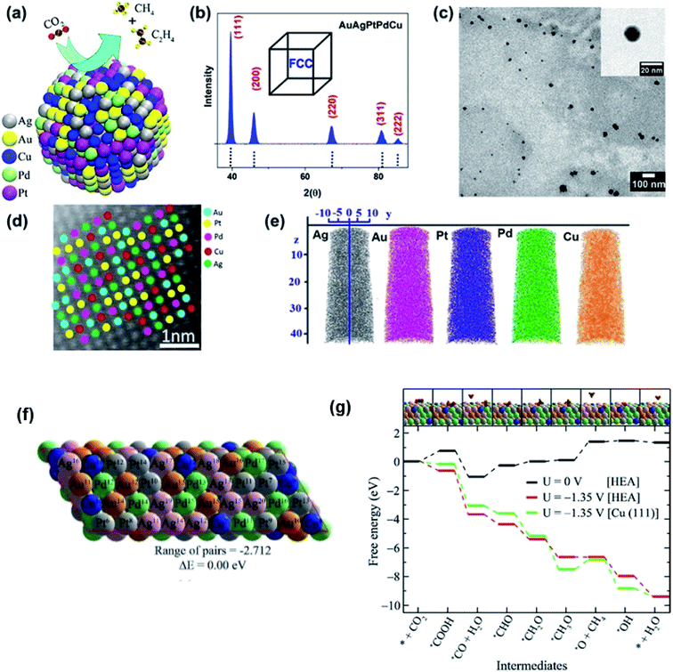 | ||
| Fig. 18 (a) Schematic of the electrocatalytic reduction of CO2 on the surface of a AuAgPtPdCu HEA. (b) X-ray diffraction (XRD), (c) transmission electron microscopy (TEM) bright-field image, and (d) high-resolution scanning transmission electron microscopy (HR-STEM) image of AuAgPtPdCu HEAs; the inset of (c) shows a high magnification image of a single AuAgPtPdCu HEA nanoparticle. (e) Chemical homogeneity of Au, Ag, Pt, Pd, and Cu. (f) Optimized structure of the special quasi-random structure of the AuAgPtPdCu HEA. (g) Free-energy diagram of CO2 reduction reaction on the AuAgPtPdCu surface. The inset shows the optimized structures of the intermediates on the HEA surface. Gray, green, pink, yellow, blue, brown, red, and orange spheres represent Pt, Pd, Ag, Au, Cu, C, O, and H atoms, respectively. Reproduced from ref. 9 with permission from the American Chemical Society. | ||
Electrochemical HER is a classic two-electron-transfer reaction occurring through the Volmer–Heyrovsky mechanism. This mechanism involves two steps: Volmer step (H+ + e− + * → H*) and Heyrovsky step (H+ + e− + H* → 0.5H2 + *). The corresponding free energy changes of the two steps are given by ΔGVolmer = EHads + ΔEZPE − TΔSH and ΔGHeyrovsky = −EHads − (ΔEZPE − TΔSH), where EHads is the hydrogen adsorption energy, ΔEZPE and ΔSH are the difference in zero-point energy and the entropy difference between the adsorbed state and H2, respectively.133 Thus, EHads determines the overall HER activity. It has been found that the catalytic activity shows a volcano trend as a function of the hydrogen adsorption strength on catalyst sites (Fig. 19a).134 The activity can be optimized when the adsorption energy of hydrogen species on catalysts is close to 0 V due to the balance of adsorption and desorption.97 Although Pt is a high-activity catalyst for the HER, its scarcity limits its application. HEAs are expected to decrease the loading of noble metals without losing their electrocatalytic efficiencies as the cocktail effect can optimize the adsorption strength of hydrogen. In the FeCoPdIrPt system, the combination of Co with strong adsorption and Ir with weak adsorption can moderate the free energy of H species.24 Pd, despite its poor HER activity, can modulate the hydrogen binding energy on the Pt surface.97 Thus, the synergic effect of the atoms in the HEA NPs leads to excellent activity towards the HER.24 In another work, an amorphous HEA of CoFeLaNiPt has also been found to show improved electrocatalytic performance compared to the individual components during the HER due to the elemental synergisms between Pt and other components on the atomic scale (Fig. 19b).6
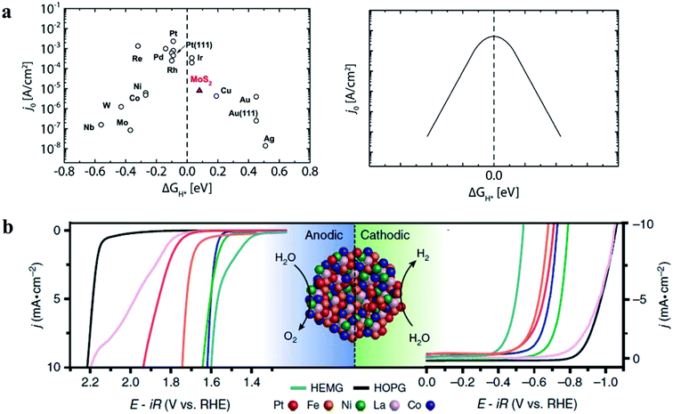 | ||
| Fig. 19 (a) Current density as a function of hydrogen adsorption energy.134 Reproduced from ref. 134 with permission from the American Chemical Society. (b) Electrocatalytic O2 and H2 evaluation of a CoFeLaNiPt HEMG-NP (High-Entropy Metallic Glasses-nanoparticle) electrocatalyst. Each material was loaded onto the HOPG (highly oriented pyrolytic graphite) substrate. Reproduced from ref. 6 with permission from Springer Nature. | ||
The ORR in fuel cells usually involves four-proton–electron transfer to form H2O.135 During this process, the adsorption energy of intermediates such as O, OH and OOH on the surface of catalysts determines the catalytic activity of the ORR. The activity of metals with strong adsorption of the intermediates is limited by the proton transfer to the intermediates. For metals with weak adsorption of the intermediates, oxygen is unstable on the catalyst surface, thus no transfer of protons and electrons to oxygen occurs. A theoretical volcano-like trend between the activity and intermediate adsorption energy is also observed (Fig. 20a and b). Although Pt is near the top of the volcano-like trend, there still exists an overpotential of ca. 0.4 V for the ORR.136,137 Pt-based alloys can reduce the overpotential by optimizing the intermediates' adsorption energy related to the pure Pt catalyst.138,139 A first principles study has proven that transition metals can weaken the adsorption of chemical species to the Pt, leading to higher ORR activity.140Fig. 20c compares the calculated free energies of the steps in the ORR on CuNiPt and CuNiPtMn HEA surface systems.79 The generation of the OOH* intermediate is the rate-limiting step of the ORR on both catalyst surfaces. Compared with CuNiPt, the addition of Mn in CuNiPtMn modulates the electronic properties of the catalyst surface, and thus optimizes the binding of OOH through the cocktail effect, resulting in enhanced activity (Fig. 20d and e).79 The cocktail effect has also been found to be applicable to design advanced ORR catalysts without Pt, such as AlCuNiAgMn, AlCuNiAgMo, and AlCuNiAgCo, which even outperform the pure Pt catalyst.79 The fact that the cocktail effect can optimize the adsorption energy of intermediates in the ORR is also proven by density functional theory (DFT), as shown in Fig. 21.141 In order to achieve a highly efficient ORR reaction, *OH and *O intermediates must not be too stable on the surface of catalysts nor be easily removed. While Pt(111) is the best crystal surface of pure metal for the ORR, the adsorption energy of *OH (∼0.1 eV) on it is still too strong.136 According to the DFT results, the surface of an HEA catalyst can offer a near-continuous distribution of adsorption energy due to the complicated surface configurations.141 Thus, a high-efficiency ORR can be achieved by tuning the compositions of the HEA catalyst with optimal adsorption energy close to the peak of the Sabatier volcano curve.142 The HEA materials become a design platform for new alloys by increasing sites with superior catalytic activity to pure Pt(111).
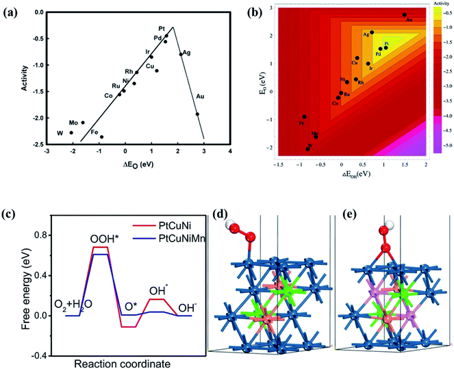 | ||
| Fig. 20 Trends in ORR activity as a function of (a) the O adsorption energy or (b) both the O and the OH binding energy. Reproduced from ref. 136 with permission from the American Chemical Society. (c) Free energy profiles of the ORR steps on the PtCuNiMn and PtCuNi. Adsorption configurations of the OOH on the (d) PtCuNi and (e) PtCuNiMn models. The colors dark blue, pink, brown, green, red and white represent the atoms of Pt, Mn, Cu, Ni, O and H, respectively. Reproduced from ref. 79 with permission from Elsevier. | ||
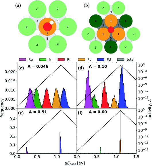 | ||
| Fig. 21 (a) *OH on-top binding. Orange (1): binding site. Light green (2): surface neighbors are coordinating once to the binding site. Light gray (3): subsurface neighbors are coordinating once to the binding site. (b) *O FCC hollow site binding. Dark green (4): surface neighbors are coordinating twice to the binding site. Dark gray (5): subsurface neighbors coordinating twice to the binding site. Distribution of adsorption energies for (c) Ir20Pd20Pt20Rh20Ru20, (d) Ir10.2Pd32.0Pt9.30Rh19.6Ru28.9, (e) Pd81.7Ru18.3, and (f) Ir17.5Pt82.5 (global maximum activity). A represents the activity. Reproduced from ref. 141 with permission from Elsevier. | ||
5. Conclusions and perspectives
The emergence of HEA nanomaterials greatly promotes the development of non-noble-metal catalysts with high efficiency.77,143–146 Due to the four core effects, HEAs can regulate the electronic and geometric structures to induce strain and d-band center shift, serving as a platform to construct catalysts with improved performance. However, the research of HEA catalysts is still in its early stage, and there still exist many issues that need to be addressed.Firstly, scientific theories for the construction of HEAs is scarce. There are a huge number of possible compositions and combinations of properties in the HEA field. Wise element design strategies for suitable compositions and structures to fit the requirements in heterogeneous catalysis thus become especially important. The rational design of HEA nanomaterials from fundamental principles has the potential to create catalysts with high activity and selectivity.147 Until now, designing new HEA materials is based on the traditional trial-and-error method which becomes very difficult due to the large number of possible compositions for HEAs. As the combinations of composition and process for producing HEAs are numerous, each HEA has its own microstructure and properties to be identified and understood. It is very important to present basic concepts relating to HEAs in advance. Using principles of materials science is the most basic way to design a new material. This route can be used at the beginning to develop new HEA nanomaterials for desired properties by fully understanding the properties of components in materials, such as the crystal structure, atomic size, atomic weight, redox potential, electronegativity, melting and boiling points, density, electron configuration, etc. Rapid-throughput screening approaches are required to vet potential HEA compositions. For example, if we want to design low-density HEAs, more light elements should be used. If HEAs with oxidation resistance are needed, more oxidation-resistant elements such as Al, Cr, and Si should be selected. If HEAs with BCC phases are desired, Al can be added by strong binding with other elements to promote the formation of a BCC phase. In catalysis, Pd instead of Pt can be chosen as one of the components in HEAs to promote the catalytic activity due to the high electro-oxidation catalytic activity and lower price of Pd. In addition, both leverage neural network (NN) and machine learning can be employed to provide insights for rational design of HEA catalysts. The NN strategy can account for the three substitution effects of HEAs (mentioned in Fig. 13) for predicting the adsorption energy of catalysts.148 Machine learning can help calculate adsorption energies of all surface sites on catalysts, allowing the optimization of the HEA compositions.9,76 Nevertheless, there is also a risk that promising alloys might be dismissed in the early stage by these methods, due to the absence of exploration of the complex links between microstructures and properties. Certainly, careful experimental assessment of HEAs is the prerequisite to obtain the microstructure characteristics and stability.
Secondly, moderate and scalable synthesis strategies are urgently needed. Although current methods mentioned in Chapter 4 have successfully crafted HEA NPs, they generally require rigorous conditions such as high pressure, temperature and inert atmospheric protection. NPs can be only immobilized on limited thermally resistant substrates rather than thermally sensitive ones. It may incur great stoichiometric deviation due to the high vapor pressure of metal elements under these extreme conditions. The mild electrosynthesis method can only craft amorphous NPs (electrosynthesis method6) or is limited by the corresponding targets (PLA approach44). It is urgent to develop a more convenient technology with low energy consumption under mild conditions for synthesizing a library of HEA nanostructures.
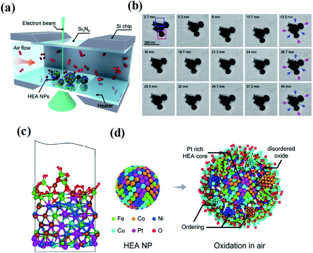
Thirdly, although HEAs have shown great potential in catalysis applications, the understanding of the whole HEA world and how HEA materials behave in complex catalysis environments is still at the infant stage. Several future trends are pointed out: more fundamental studies on HEA structures are required. In most cases, the catalytic performance of HEA catalysts is simply explained by the synergetic effect between multiple elements. Very limited studies aim to establish an in-depth understanding of the structure–performance relationship. HEA structures with mutual interactions between different atoms, lattice distortion, metastable structures, stacking fault energy, electrical and thermal conductivity, diffusion coefficients, corrosion and oxidation are desired to fully understand the relationship between the structure and performance. Moreover, a theoretical model including microstructure details in HEAs will be instructive for establishing an accurate structure–performance relationship over HEA catalysts. Architectures in the atomic structures of HEAs can be explored in a systematic and site-specific manner. Otherwise, the possibility of comprehensively exploring such systems would be precluded. Accurate models for catalyst selections need to be built. The lack of such models makes the design of high-activity HEA catalysts difficult. The chosen descriptors determined the catalytic activities of catalysts. For example, the Sabatier principle shows a volcano-type relationship between catalytic activities and adsorption energy, whereas it is a linear relationship in the Brønsted–Evans–Polanyi behavior.149,150 Due to the interactions of elements in alloys, the properties in terms of adsorption energy may be more complex. Establishing a descriptor suitable for HEA materials will contribute to guiding the selection of high-activity catalysts. The behavior of HEA NPs in real service environments is investigated. In the application of industrial catalysis, critical environments, such as high temperature/pressure, oxidizing/reducing conditions, and extreme pH solution, are usually involved.151 Since it is challenging to obtain structural and compositional information of such nanoscale HEAs at spatial and temporal resolution, there is still very limited knowledge of the behavior of HEA NPs in these environments. Shahbazian-Yassar et al. employed in situ gas-cell TEM to investigate the oxidation behavior of Fe0.28Co0.21Ni0.20Cu0.08Pt0.23 HEA NPs at 400 °C and in an atmospheric pressure air environment (Fig. 22).152 Although the overall oxidation kinetics of the HEA NPs are slower than that of both monometallic and bimetallic alloy NPs with similar principal elements, the oxidation of HEA NPs governed by the Kirkendall effect has been found involving outward diffusion of Fe, Co, Ni, and Cu to form an oxide layer with a concentration gradient. Pt stays in the HEA core region during the oxidation process due to its nonreactivity. Studies on other extreme conditions such as oxidizing/reducing conditions and extreme pH solution are also needed, yet are still scarce, but are crucial for understanding HEA behavior in these environments and providing insights in designing chemical/thermal corrosion-resistant alloys for various applications.
 | ||
| Fig. 22 (a) Schematic of the in situ gas-cell in air. (b) In situ TEM image sequences of HEA NPs during annealing in air to study the oxidation of HEA NPs. (c) Exemplary atomic model for an oxidized slab after equilibration. (d) Schematic illustration of the oxidation process of HEA NPs. Reproduced from ref. 152 with permission from the American Chemical Society. | ||
Fourthly, more research can be focused on high-entropy ceramics (HECs) such as nitrides, carbides, oxides, and sulfides. A few studies have indicated that four core effects of HEAs are also applicable in HECs. As some conventional phosphides/sulfides/oxides/carbides/nitrides have been proven as efficient catalysts,153–157 HECs are expected to have promising applications in catalysis via their four core effects. Unfortunately, there are few reports on the synthesis of HEC nanomaterials, limiting their research in the field of catalysis.
Based on these deliberations, HEAs have thrust us into a new world of seemingly infinite possibility. Research on HEA-based catalysis has been attracting increasing attention. Recent studies indeed offer significant potential to improve our fundamental understanding of the catalytic behavior of HEAs. Nevertheless, future efforts should focus on key features presented by the microstructures of HEAs, rather than wandering in its limitless expanse.
Conflicts of interest
There are no conflicts to declare.Acknowledgements
This work was supported by the National Key Research and Development Program of China (2018YFE0208500), the Major Research Plan of the National Natural Science Foundation of China (91963206), the National Natural Science Foundation of China (52072169, 51627810, 51972164), the Natural Science Foundation of Jiangsu Province (BK20201202), the Program for Guangdong Introducing Innovative and Enterpreneurial Teams (2019ZT08L101), the Open Fund of Wuhan National Laboratory for Optoelectronics (2018WNLOKF020), Postgraduate Research & Practice Innovation Program of Jiangsu Province (KYCX19_0043), the Fundamental Research Funds for the Central Universities (14380193), and Civil Aerospace Technology Research Project (B0108).References
- Y. G. Yao, Z. Y. Liu, P. F. Xie, Z. N. Huang, T. Y. Li, D. Morris, Z. Finfrock, J. H. Zhou, M. L. Jiao, J. L. Gao, Y. M. Mao, J. W. Miao, P. Zhang, R. Shahbazian-Yassar, C. Wang, G. F. Wang and L. B. Hu, Sci. Adv., 2020, 6, eaaz0510 CrossRef CAS PubMed.
- X. Z. Wang, Q. Dong, H. Y. Qiao, Z. N. Huang, M. T. Saray, G. Zhong, Z. W. Lin, M. J. Cui, A. Brozena, M. Hong, Q. Q. Xia, J. L. Gao, G. Chen, R. Shahbazian-Yassar, D. W. Wang and L. B. Hu, Adv. Mater., 2020, 32, 2002853 CrossRef CAS PubMed.
- J. W. Yeh, S. K. Chen, S. J. Lin, J. Y. Gan, T. S. Chin, T. T. Shun, C. H. Tsau and S. Y. Chang, Adv. Eng. Mater., 2004, 6, 299–303 CrossRef CAS.
- D. B. Miracle and O. N. Senkov, Acta Mater., 2017, 122, 448–511 CrossRef CAS.
- Y. Zhang, Y. J. Zhou, J. P. Lin, G. L. Chen and P. K. Liaw, Adv. Eng. Mater., 2008, 10, 534–538 CrossRef CAS.
- M. W. Glasscott, A. D. Pendergast, S. Goines, A. R. Bishop, A. T. Hoang, C. Renault and J. E. Dick, Nat. Commun., 2019, 10, 2650 CrossRef PubMed.
- P. F. Xie, Y. G. Yao, Z. N. Huang, Z. Y. Liu, J. L. Zhang, T. Y. Li, G. F. Wang, R. Shahbazian-Yassar, L. B. Hu and C. Wang, Nat. Commun., 2019, 10, 4011 CrossRef PubMed.
- W. J. Dai, T. Lu and Y. Pan, J. Power Sources, 2019, 430, 104–111 CrossRef CAS.
- S. Nellaiappan, N. K. Katiyar, R. Kumar, A. Parui, K. D. Malviya, K. G. Pradeep, A. K. Singh, S. Sharma, C. S. Tiwary and K. Biswas, ACS Catal., 2020, 10, 3658–3663 CrossRef CAS.
- S. Guo and C. T. Liu, Prog. Nat. Sci.: Mater. Int., 2011, 21, 433–446 CrossRef.
- J. Chen, X. Y. Zhou, W. L. Wang, B. Liu, Y. K. Lv, D. P. Xu, W. Yang and Y. Liu, J. Alloys Compd., 2019, 785, 1294 CrossRef CAS.
- K. N. Zhao, X. Li and D. Su, Acta Phys.-Chim. Sin., 2021, 37, 2009077 Search PubMed.
- A. Amiri and R. Shahbazian-Yassar, J. Mater. Chem. A, 2021, 9, 782–823 RSC.
- X. H. Yan and Y. Zhang, Scr. Mater., 2020, 187, 188–193 CrossRef CAS.
- G. M. Tomboc, T. Kwon, J. Joo and K. Lee, J. Mater. Chem. A, 2020, 8, 14844–14862 RSC.
- B. Yaakobi, T. R. Boehly, D. D. Meyerhofer, T. J. B. Collins, B. A. Remington, P. G. Allen, S. M. Pollaine, H. E. Lorenzana and J. H. Eggert, Phys. Rev. Lett., 2005, 95, 075501 CrossRef CAS PubMed.
- Z. Y. Lv, X. J. Liu, B. Jia, H. Wang, Y. Wu and Z. P. Lu, Sci. Rep., 2016, 6, 34213 CrossRef CAS PubMed.
- Y. G. Yao, Z. N. Huang, P. F. Xie, S. D. Lacey, R. J. Jacob, H. Xie, F. J. Chen, A. M. Nie, T. C. Pu, M. Rehwoldt, D. W. Yu, M. R. Zachariah, C. Wang, R. Shahbazian-Yassar, J. Li and L. B. Hu, Science, 2018, 359, 1489–1494 CrossRef CAS PubMed.
- S. Peulon and D. Lincot, Adv. Mater., 1996, 8, 166–170 CrossRef CAS.
- J. E. Dick, C. Renault, B. K. Kim and A. J. Bard, Angew. Chem., Int. Ed., 2014, 53, 11859–11862 CrossRef CAS PubMed.
- K. Huang, B. W. Zhang, J. S. Wu, T. Y. Zhang, D. D. Peng, X. Cao, Z. Zhang, Z. Li and Y. Z. Huang, J. Mater. Chem. A, 2020, 8, 11938–11947 RSC.
- A. Villa, D. Wang, D. S. Su and L. Prati, Catal. Sci. Technol., 2015, 5, 55–68 RSC.
- E. D. Bojesen and B. B. Iversen, Crystengcomm, 2016, 18, 8332–8353 RSC.
- S. J. Gao, S. Y. Hao, Z. N. Huang, Y. F. Yuan, S. Han, L. C. Lei, X. W. Zhang, R. Shahbazian-Yassar and J. Lu, Nat. Commun., 2020, 11, 2016 CrossRef CAS PubMed.
- E. V. Shevchenko, D. V. Talapin, H. Schnablegger, A. Kornowski, O. Festin, P. Svedlindh, M. Haase and H. Weller, J. Am. Chem. Soc., 2003, 125, 9090–9101 CrossRef CAS PubMed.
- M. Bondesgaard, N. L. N. Broge, A. Mamakhel, M. Bremholm and B. B. Iversen, Adv. Funct. Mater., 2019, 29, 1905933 CrossRef CAS.
- C. J. Wang, X. R. Bao, G. W. Du, Y. Wang, K. Chen, M. L. Shen and L. Z. Wang, Int. Urol. Nephrol., 2014, 46, 1609–1617 CrossRef CAS PubMed.
- N. L. N. Broge, M. Bondesgaard, F. Sondergaard-Pedersen, M. Roelsgaard and B. B. Iversen, Angew. Chem., Int. Ed., 2020, 59, 21920–21924 CrossRef CAS PubMed.
- M. Y. Rekha, N. Mallik and C. Srivastava, Sci. Rep., 2018, 8, 8737 CrossRef CAS PubMed.
- S. H. Zhou, G. S. Jackson and B. Eichhorn, Adv. Funct. Mater., 2007, 17, 3099–3104 CrossRef CAS.
- S. Alayoglu and B. Eichhorn, J. Am. Chem. Soc., 2008, 130, 17479–17486 CrossRef CAS PubMed.
- M. M. Liu, Z. H. Zhang, F. Okejiri, S. Z. Yang, S. H. Zhou and S. Dai, Adv. Mater. Interfaces, 2019, 6, 1900015 CrossRef CAS.
- Q. L. Li, H. L. Li, V. G. Pol, I. Bruckental, Y. Koltypin, J. Calderon-Moreno, I. Nowik and A. Gedanken, New J. Chem., 2003, 27, 1194–1199 RSC.
- K. S. Suslick and G. J. Price, Annu. Rev. Mater. Sci., 1999, 29, 295–326 CrossRef CAS.
- S. H. Joo, J. W. Bae, W. Y. Park, Y. Shimada, T. Wada, H. S. Kim, A. Takeuchi, T. J. Konno, H. Kato and I. V. Okulov, Adv. Mater., 2020, 32, 1906160 CrossRef CAS PubMed.
- Z. Y. Jin, J. Lv, H. L. Jia, W. H. Liu, H. L. Li, Z. H. Chen, X. Lin, G. Q. Xie, X. J. Liu, S. H. Sun and H. J. Qiu, Small, 2019, 15, 1904180 CrossRef CAS PubMed.
- C. X. Xu, R. Y. Wang, Y. Zhang and Y. Ding, Nanoscale, 2010, 2, 906–909 RSC.
- H. J. Qiu, G. Fang, Y. R. Wen, P. Liu, G. Q. Xie, X. J. Liu and S. H. Sun, J. Mater. Chem. A, 2019, 7, 6499–6506 RSC.
- M. M. Biener, J. Biener, A. Wichmann, A. Wittstock, T. F. Baumann, M. Baumer and A. V. Hamza, Nano Lett., 2011, 11, 3085–3090 CrossRef CAS PubMed.
- C. F. Tsai, P. W. Wu, P. Lin, C. G. Chao and K. Y. Yeh, Jpn. J. Appl. Phys., 2008, 47, 5755–5761 CrossRef CAS.
- G. W. Yang, Prog. Mater. Sci., 2007, 52, 648–698 CrossRef CAS.
- A. V. Kabashin and M. Meunier, J. Appl. Phys., 2003, 94, 7941–7943 CrossRef CAS.
- V. Amendola, S. Scaramuzza, F. Carraro and E. Cattaruzza, J. Colloid Interface Sci., 2017, 489, 18–27 CrossRef CAS PubMed.
- F. Waag, Y. Li, A. R. Ziefuss, E. Bertin, M. Kamp, V. Duppel, G. Marzun, L. Kienle, S. Barcikowski and B. Gokce, RSC Adv., 2019, 9, 18547–18558 RSC.
- P. Wagener, A. Schwenke, B. N. Chichkov and S. Barcikowski, J. Phys. Chem. C, 2010, 114, 7618–7625 CrossRef CAS.
- E. P. George, D. Raabe and R. O. Ritchie, Nat. Rev. Mater., 2019, 4, 515–534 CrossRef CAS.
- H. Q. Song, F. Y. Tian, Q. M. Hu, L. Vitos, Y. D. Wang, J. Shen and N. X. Chen, Phys. Rev. Mater., 2017, 1, 023404 CrossRef.
- B. Fultz, Prog. Mater. Sci., 2010, 55, 247–352 CrossRef CAS.
- J. W. Yeh, JOM, 2013, 65, 1759–1771 CrossRef CAS.
- J. W. Yeh, Ann. Chimie Sci. Matériaux, 2006, 31, 633–648 CrossRef CAS.
- F. Y. Tian, Front. Mater., 2017, 4, 36 CrossRef.
- B. Cantor, I. T. H. Chang, P. Knight and A. J. B. Vincent, Mater. Sci. Eng., A, 2004, 375, 213–218 CrossRef.
- Y. Pei, G. B. Zhou, N. Luan, B. N. Zong, M. H. Qiao and F. Tao, Chem. Soc. Rev., 2012, 41, 8140–8162 RSC.
- J. F. Deng, H. X. Li and W. J. Wang, Catal. Today, 1999, 51, 113–125 CrossRef CAS.
- K. V. Yusenko, S. Riva, P. A. Carvalho, M. V. Yusenko, S. Arnaboldi, A. S. Sukhikh, M. Hanfland and S. A. Gromilov, Scr. Mater., 2017, 138, 22–27 CrossRef CAS.
- P. F. Xie, Y. G. Yao, Z. N. Huang, Z. Y. Liu, J. L. Zhang, T. Y. Li, G. F. Wang, R. Shahbazian-Yassar, L. B. Hu and C. Wang, Nat. Commun., 2019, 10, 4011 CrossRef PubMed.
- M. H. Tsai and J. W. Yeh, Mater. Res. Lett., 2014, 2, 107–123 CrossRef.
- Y. F. Kao, T. J. Chen, S. K. Chen and J. W. Yeh, J. Alloys Compd., 2009, 488, 57–64 CrossRef CAS.
- S. Ranganathan, Curr. Sci., 2003, 85, 1404–1406 Search PubMed.
- Y. J. Zhou, Y. Zhang, Y. L. Wang and G. L. Chen, Appl. Phys. Lett., 2007, 90, 181904 CrossRef.
- S. Singh, N. Wanderka, B. S. Murty, U. Glatzel and J. Banhart, Acta Mater., 2011, 59, 182–190 CrossRef CAS.
- K. Zhao, X. X. Xia, H. Y. Bai, D. Q. Zhao and W. H. Wang, Appl. Phys. Lett., 2011, 98, 141913 CrossRef.
- R. N. Singh, A. Singh and Anindita, Int. J. Hydrogen Energy, 2009, 34, 2052–2057 CrossRef CAS.
- Z. Qi, H. R. Geng, X. G. Wang, C. C. Zhao, H. Ji, C. Zhang, J. L. Xu and Z. H. Zhang, J. Power Sources, 2011, 196, 5823–5828 CrossRef CAS.
- S. Kasatikov, A. Fantin, A. M. Manzoni, S. Sakhonenkov, A. Makarova, D. Smirnov, E. O. Filatova and G. Schumacher, J. Alloys Compd., 2021, 857, 157597 CrossRef CAS.
- G. L. Zhang, K. S. Ming, J. L. Kang, Q. Huang, Z. J. Zhang, X. R. Zheng and X. F. Bi, Electrochim. Acta, 2018, 279, 19–23 CrossRef CAS.
- K. Y. Tsai, M. H. Tsai and J. W. Yeh, Acta Mater., 2013, 61, 4887–4897 CrossRef CAS.
- Q. F. He and Y. Yang, Front. Mater., 2018, 5, 42 CrossRef.
- K. Chen, S. Kim, R. Rajendiran, K. Prabakar, G. Z. Li, Z. C. Shi, C. Y. Jeong, J. Kang and O. L. Li, J. Colloid Interface Sci., 2021, 582, 977–990 CrossRef CAS PubMed.
- C. F. Tsai, K. Y. Yeh, P. W. Wu, Y. F. Hsieh and P. Lin, J. Alloys Compd., 2009, 478, 868–871 CrossRef CAS.
- A. L. Wang, H. C. Wan, H. Xu, Y. X. Tong and G. R. Li, Electrochim. Acta, 2014, 127, 448–453 CrossRef CAS.
- J. Barranco and A. R. Pierna, J. Non-Cryst. Solids, 2008, 354, 5153–5155 CrossRef CAS.
- X. T. Chen, C. H. Si, Y. L. Gao, J. Frenzel, J. Z. Sun, G. Eggeler and Z. H. Zhang, J. Power Sources, 2015, 273, 324–332 CrossRef CAS.
- Z. Y. Lv, X. J. Liu, B. Jia, H. Wang, Y. Wu and Z. P. Lu, Sci. Rep., 2016, 6, 34213 CrossRef CAS PubMed.
- S. K. Wu, Y. Pan, N. Wang, T. Lu and W. J. Dai, Int. J. Miner., Metall. Mater., 2019, 26, 124–132 CrossRef CAS.
- D. S. Wu, K. Kusada, T. Yamamoto, T. Toriyama, S. Matsumura, I. Gueye, O. Seo, J. Kim, S. Hiroi, O. Sakata, S. Kawaguchi, Y. Kubota and H. Kitagawa, Chem. Sci., 2020, 11, 12731–12736 RSC.
- C. S. Zhou, R. C. Bowman, Z. Z. Fang, J. Lu, L. Xu, P. Sun, H. Liu, H. Wu and Y. Liu, ACS Appl. Mater. Interfaces, 2019, 11, 38868–38879 CrossRef CAS PubMed.
- M. M. Shi, D. Bao, S. J. Li, B. R. Wulan, J. M. Yan and Q. Jiang, Adv. Energy Mater., 2018, 8, 1800124 CrossRef.
- S. Y. Li, X. W. Tang, H. L. Jia, H. L. Li, G. Q. Xie, X. J. Liu, X. Lin and H. J. Qiu, J. Catal., 2020, 383, 164–171 CrossRef CAS.
- Y. G. Yao, Z. N. Huang, T. Y. Li, H. Wang, Y. F. Liu, H. S. Stein, Y. M. Mao, J. L. Gao, M. L. Jiao, Q. Dong, J. Q. Dai, P. F. Xie, H. Xie, S. D. Lacey, I. Takeuchi, J. M. Gregoire, R. Z. Jiang, C. Wang, A. D. Taylor, R. Shahbazian-Yassar and L. B. Hu, Proc. Natl. Acad. Sci. U. S. A., 2020, 117, 6316–6322 CrossRef CAS PubMed.
- S. A. Kube and J. Schroers, Scr. Mater., 2020, 186, 392–400 CrossRef CAS.
- C. J. H. Jacobsen, S. Dahl, B. S. Clausen, S. Bahn, A. Logadottir and J. K. Norskov, J. Am. Chem. Soc., 2001, 123, 8404–8405 CrossRef CAS PubMed.
- P. M. Forster, J. Eckert, B. D. Heiken, J. B. Parise, J. W. Yoon, S. H. Jhung, J. S. Chang and A. K. Cheetham, J. Am. Chem. Soc., 2006, 128, 16846–16850 CrossRef CAS PubMed.
- K. S. Suslick, S. B. Choe, A. A. Cichowlas and M. W. Grinstaff, Nature, 1991, 353, 414–416 CrossRef CAS.
- H. Zahn and J. Kramer, Z. Phys., 1933, 86, 413–420 CrossRef CAS.
- H. I. Schlesinger, H. C. Brown, A. E. Finholt, J. R. Gilbreath, H. R. Hoekstra and E. K. Hyde, J. Am. Chem. Soc., 1953, 75, 215–219 CrossRef CAS.
- J. Vanwonterghem, S. Morup, C. J. W. Koch, S. W. Charles and S. Wells, Nature, 1986, 322, 622–623 CrossRef.
- Z. Li, J. Y. Fu, Y. Feng, C. K. Dong, H. Liu and X. W. Du, Nat. Catal., 2019, 2, 1107–1114 CrossRef CAS.
- A. Molnar, G. V. Smith and M. Bartok, Adv. Catal., 1989, 36, 329–383 CAS.
- H. Li, K. Shin and G. Henkelman, J. Chem. Phys., 2018, 149, 174705 CrossRef PubMed.
- J. W. Yeh, S. K. Chen, J. Y. Gan, S. J. Lin, T. S. Chin, T. T. Shun, C. H. Tsau and S. Y. Chang, Metall. Mater. Trans. A, 2004, 35a, 2533–2536 CrossRef CAS.
- D. F. Wu, J. C. Zhou and Y. D. Li, AIChE J., 2007, 53, 2618–2629 CrossRef CAS.
- D. F. Wu, L. Y. Song, B. Q. Zhang and Y. D. Li, Chem. Eng. Sci., 2003, 58, 3995–4004 CrossRef CAS.
- V. Stamenkovic, B. S. Mun, K. J. J. Mayrhofer, P. N. Ross, N. M. Markovic, J. Rossmeisl, J. Greeley and J. K. Norskov, Angew. Chem., Int. Ed., 2006, 45, 2897–2901 CrossRef CAS PubMed.
- A. J. Medford, A. Vojvodic, J. S. Hummelshoj, J. Voss, F. Abild-Pedersen, F. Studt, T. Bligaard, A. Nilsson and J. K. Norskov, J. Catal., 2015, 328, 36–42 CrossRef CAS.
- F. Abild-Pedersen, J. Greeley, F. Studt, J. Rossmeisl, T. R. Munter, P. G. Moses, E. Skulason, T. Bligaard and J. K. Norskov, Phys. Rev. Lett., 2007, 99, 016105 CrossRef CAS PubMed.
- W. C. Sheng, M. Myint, J. G. G. Chen and Y. S. Yan, Energy Environ. Sci., 2013, 6, 1509–1512 RSC.
- D. Voiry, H. Yamaguchi, J. W. Li, R. Silva, D. C. B. Alves, T. Fujita, M. W. Chen, T. Asefa, V. B. Shenoy, G. Eda and M. Chhowalla, Nat. Mater., 2013, 12, 850–855 CrossRef CAS PubMed.
- M. Mavrikakis, B. Hammer and J. K. Norskov, Phys. Rev. Lett., 1998, 81, 2819–2822 CrossRef.
- J. R. Kitchin, J. K. Norskov, M. A. Barteau and J. G. Chen, Phys. Rev. Lett., 2004, 93, 156801 CrossRef CAS PubMed.
- J. Hwang, R. R. Rao, L. Giordano, Y. Katayama, Y. Yu and Y. Shao-Horn, Science, 2017, 358, 751–756 CrossRef CAS PubMed.
- X. L. Tian, X. Zhao, Y. Q. Su, L. J. Wang, H. M. Wang, D. Dang, B. Chi, H. F. Liu, E. J. M. Hensen, X. W. Lou and B. Y. Xia, Science, 2019, 366, 850–856 CrossRef CAS PubMed.
- B. Hammer and J. K. Norskov, Surf. Sci., 1995, 343, 211–220 CrossRef CAS.
- L. A. Kibler, A. M. El-Aziz, R. Hoyer and D. M. Kolb, Angew. Chem., Int. Ed., 2005, 44, 2080–2084 CrossRef CAS PubMed.
- M. C. Luo and S. J. Guo, Nat. Rev. Mater., 2017, 2, 17059 CrossRef CAS.
- S. Schnur and A. Gross, Phys. Rev. B: Condens. Matter Mater. Phys., 2010, 81, 033402 CrossRef.
- K. Yan, T. A. Maark, A. Khorshidi, V. A. Sethuraman, A. A. Peterson and P. R. Guduru, Angew. Chem., Int. Ed., 2016, 55, 6175–6181 CrossRef CAS PubMed.
- H. T. Wang, S. C. Xu, C. Tsai, Y. Z. Li, C. Liu, J. Zhao, Y. Y. Liu, H. Y. Yuan, F. Abild-Pedersen, F. B. Prinz, J. K. Norskov and Y. Cui, Science, 2016, 354, 1031–1036 CrossRef CAS PubMed.
- L. Wang, Z. H. Zeng, W. P. Gao, T. Maxson, D. Raciti, M. Giroux, X. Q. Pan, C. Wang and J. Greeley, Science, 2019, 363, 870–874 CrossRef CAS PubMed.
- M. Escudero-Escribano, P. Malacrida, M. H. Hansen, U. G. Vej-Hansen, A. Velazquez-Palenzuela, V. Tripkovic, J. Schiotz, J. Rossmeisl, I. E. L. Stephens and I. Chorkendorff, Science, 2016, 352, 73–76 CrossRef CAS PubMed.
- P. Strasser, S. Koh, T. Anniyev, J. Greeley, K. More, C. F. Yu, Z. C. Liu, S. Kaya, D. Nordlund, H. Ogasawara, M. F. Toney and A. Nilsson, Nat. Chem., 2010, 2, 454–460 CrossRef CAS PubMed.
- M. Asano, R. Kawamura, R. Sasakawa, N. Todoroki and T. Wadayama, ACS Catal., 2016, 6, 5285–5289 CrossRef CAS.
- N. Todoroki, Y. Iijima, R. Takahashi, Y. Asakimori and T. Wadayama, J. Electrochem. Soc., 2013, 160, F591–F596 CrossRef CAS.
- I. E. L. Stephens, A. S. Bondarenko, U. Gronbjerg, J. Rossmeisl and I. Chorkendorff, Energy Environ. Sci., 2012, 5, 6744–6762 RSC.
- V. Jalan and E. J. Taylor, J. Electrochem. Soc., 1983, 130, 2299–2301 CrossRef CAS.
- Z. Li, J. Y. Fu, Y. Feng, C. K. Dong, H. Liu and X. W. Du, Nat. Catal., 2019, 2, 1107–1114 CrossRef CAS.
- H. Zhang, Y. Pan, Y. Z. He and H. S. Jiao, Appl. Surf. Sci., 2011, 257, 2259–2263 CrossRef CAS.
- J. Li, Q. H. Fang, B. Liu and Y. Liu, Acta Mater., 2018, 147, 35–41 CrossRef CAS.
- Z. Q. Fu, W. P. Chen, H. M. Wen, D. L. Zhang, Z. Chen, B. L. Zheng, Y. Z. Zhou and E. J. Lavernia, Acta Mater., 2016, 107, 59–71 CrossRef CAS.
- B. Gludovatz, A. Hohenwarter, K. V. S. Thurston, H. B. Bei, Z. G. Wu, E. P. George and R. O. Ritchie, Nat. Commun., 2016, 7, 10602 CrossRef CAS PubMed.
- S. Y. Liu and Y. J. Wei, Extreme Mechanics Letters, 2017, 11, 84–88 CrossRef.
- A. J. Zaddach, C. Niu, C. C. Koch and D. L. Irving, JOM, 2013, 65, 1780–1789 CrossRef CAS.
- M. Kim, C. Lee, S. M. Ko and J. M. Nam, J. Solid State Chem., 2019, 270, 295–303 CrossRef CAS.
- K. Jiang, H. X. Zhang, S. Z. Zou and W. B. Cai, Phys. Chem. Chem. Phys., 2014, 16, 20360–20376 RSC.
- T. Bligaard and J. K. Norskov, Electrochim. Acta, 2007, 52, 5512–5516 CrossRef CAS.
- C. M. Clausen, T. A. A. Batchelor, J. K. Pedersen and J. Rossmeisl, Adv. Sci., 2021, 8, 2003357 CrossRef CAS PubMed.
- L. Luo, Z. Y. Duan, H. Li, J. Kim, G. Henkelman and R. M. Crooks, J. Am. Chem. Soc., 2017, 139, 5538–5546 CrossRef CAS PubMed.
- Y. W. Wang, W. J. Qiu, E. H. Song, F. Gu, Z. H. Zheng, X. L. Zhao, Y. Q. Zhao, J. J. Liu and W. Q. Zhang, Natl. Sci. Rev., 2018, 5, 327–341 CrossRef CAS.
- C. T. Campbell, Acc. Chem. Res., 2019, 52, 984–993 CrossRef CAS PubMed.
- F. Z. Song, W. Li and Y. J. Sun, Inorganics, 2017, 5, 40 CrossRef.
- F. Z. Song, W. Li, J. Q. Yang, G. Q. Han, T. Yan, X. Liu, Y. Rao, P. L. Liao, Z. Cao and Y. J. Sun, ACS Energy Lett., 2019, 4, 1594–1601 CrossRef CAS.
- T. Loffler, A. Savan, H. Meyer, M. Meischein, V. Strotkotter, A. Ludwig and W. Schuhmann, Angew. Chem., Int. Ed., 2020, 59, 5844–5850 CrossRef PubMed.
- J. K. Norskov, T. Bligaard, A. Logadottir, J. R. Kitchin, J. G. Chen, S. Pandelov and J. K. Norskov, J. Electrochem. Soc., 2005, 152, J23–J26 CrossRef CAS.
- J. D. Benck, T. R. Hellstern, J. Kibsgaard, P. Chakthranont and T. F. Jaramillo, ACS Catal., 2014, 4, 3957–3971 CrossRef CAS.
- W. Li, D. H. Xiong, X. F. Gao and L. F. Liu, Chem. Commun., 2019, 55, 8744–8763 RSC.
- J. K. Norskov, J. Rossmeisl, A. Logadottir, L. Lindqvist, J. R. Kitchin, T. Bligaard and H. Jonsson, J. Phys. Chem. B, 2004, 108, 17886–17892 CrossRef CAS.
- V. Viswanathan, H. A. Hansen, J. Rossmeisl and J. K. Norskov, ACS Catal., 2012, 2, 1654–1660 CrossRef CAS.
- V. R. Stamenkovic, B. S. Mun, M. Arenz, K. J. J. Mayrhofer, C. A. Lucas, G. F. Wang, P. N. Ross and N. M. Markovic, Nat. Mater., 2007, 6, 241–247 CrossRef CAS PubMed.
- J. Greeley, I. E. L. Stephens, A. S. Bondarenko, T. P. Johansson, H. A. Hansen, T. F. Jaramillo, J. Rossmeisl, I. Chorkendorff and J. K. Norskov, Nat. Chem., 2009, 1, 552–556 CrossRef CAS PubMed.
- Z. Y. Duan and G. F. Wang, Phys. Chem. Chem. Phys., 2011, 13, 20178–20187 RSC.
- T. A. A. Batchelor, J. K. Pedersen, S. H. Winther, I. E. Castelli, K. W. Jacobsen and J. Rossmeisl, Joule, 2019, 3, 834–845 CrossRef CAS.
- K. D. Jensen, J. Tymoczko, J. Rossmeisl, A. S. Bandarenka, I. Chorkendorff, M. Escudero-Escribano and I. E. L. Stephens, Angew. Chem., Int. Ed., 2018, 57, 2800–2805 CrossRef CAS PubMed.
- K. D. Gilroy, A. Ruditskiy, H. C. Peng, D. Qin and Y. N. Xia, Chem. Rev., 2016, 116, 10414–10472 CrossRef CAS PubMed.
- M. K. Debe, Nature, 2012, 486, 43–51 CrossRef CAS PubMed.
- H. A. Gasteiger and N. M. Markovic, Science, 2009, 324, 48–49 CrossRef CAS PubMed.
- I. E. L. Stephens, J. Rossmeisl and I. Chorkendorff, Science, 2016, 354, 1378–1379 CrossRef CAS PubMed.
- J. K. Pedersen, T. A. A. Batchelor, D. X. Yan, L. E. J. Skjegstad and J. Rossmeisl, Curr. Opin. Electrochem., 2021, 26, 100651 CrossRef CAS.
- Z. L. Lu, Z. W. Chen and C. V. Singh, Matter, 2020, 3, 1318–1333 CrossRef.
- A. Logadottir, T. H. Rod, J. K. Norskov, B. Hammer, S. Dahl and C. J. H. Jacobsen, J. Catal., 2001, 197, 229–231 CrossRef CAS.
- T. Bligaard, J. K. Norskov, S. Dahl, J. Matthiesen, C. H. Christensen and J. Sehested, J. Catal., 2004, 224, 206–217 CrossRef CAS.
- Y. Z. Shi, B. Yang and P. K. Liaw, Metals, 2017, 7, 43 CrossRef.
- B. Song, Y. Yang, M. Rabbani, T. T. Yang, K. He, X. B. Hu, Y. F. Yuan, P. Ghildiyal, V. P. Dravid, M. R. Zachariah, W. A. Saidi, Y. Z. Liu and R. Shahbazian-Yassar, ACS Nano, 2020, 14, 15131–15143 CrossRef PubMed.
- C. F. Wise and J. M. Mayer, J. Am. Chem. Soc., 2020, 142, 12544–12545 CrossRef CAS PubMed.
- H. M. Sun, Z. H. Yan, F. M. Liu, W. C. Xu, F. Y. Cheng and J. Chen, Adv. Mater., 2020, 32, 1806326 CrossRef CAS PubMed.
- Y. L. Zhu, Q. Lin, Y. J. Zhong, H. A. Tahini, Z. P. Shao and H. T. Wang, Energy Environ. Sci., 2020, 13, 3361–3392 RSC.
- T. X. Nguyen, Y. H. Su, C. C. Lin, J. Ruan and J. M. Ting, Adv. Sci., 2021, 8, 2002446 CrossRef CAS PubMed.
- H. Chen, Y. F. Sun, S. Z. Yang, H. Wang, W. Dmowski, T. Egami and S. Dai, Chem. Commun., 2020, 56, 15056–15059 RSC.
| This journal is © The Royal Society of Chemistry 2021 |


