
Mixed donor, phenanthroline photoactive MOFs with favourable CO2 selectivity†
Caitlin J.
Setter
ab,
Michael B.
Price
c,
Luke
Conte
d,
Wolfgang
Schmitt
 e,
Stuart R.
Batten
f,
Christopher
Richardson
d,
Matthew R.
Hill
bg,
Ravichandar
Babarao
h and
Lauren K.
Macreadie
*agi
e,
Stuart R.
Batten
f,
Christopher
Richardson
d,
Matthew R.
Hill
bg,
Ravichandar
Babarao
h and
Lauren K.
Macreadie
*agi
aSchool of Fundamental Sciences, Massey University, Palmerston North, 4442, New Zealand
bDepartment of Chemical Engineering, Monash University, Clayton, Victoria 3800, Australia
cSchool of Chemical and Physical Sciences, Victoria University of Wellington, Wellington 6140, New Zealand
dSchool of Chemistry and Molecular Bioscience, University of Wollongong, Wollongong, NSW 2522, Australia
eSchool of Chemistry & SFI AMBER Centre, Trinity College Dublin, Dublin 2, Ireland
fSchool of Chemistry, Monash University, Clayton, Victoria 3800, Australia
gCSIRO, Normanby Road, Clayton, Victoria 3168, Australia
hSchool of Science, RMIT University, Melbourne, Victoria 3001, Australia
iSchool of Chemistry, University of Sydney, Sydney, NSW 2006, Australia. E-mail: lauren.macreadie@sydney.edu.au
First published on 2nd September 2020
Abstract
Mixed donor phenanthroline-carboxylate linkers were combined with MnII or ZnII to form photoactive MOFs with large pore apertures. The MOFs display high CO2 adsorption capacities, which consequently causes structural framework flexibility, and align with favorable metrics for selective CO2 capture. The photophysical properties of the MOFs were investigated, with the MnII MOF giving rise to short triplet LMCT lifetimes.
Decades of global research into metal–organic framework (MOF) chemistry has garnered a sophisticated understanding of strategies to create framework materials with desired properties. This involves designing frameworks with premediated attributes such as open metal sites (OMS),1 inherent structural flexibility,2 tailored pore shapes,3,4 magnetic behaviour5 and photoluminescent properties.6,7 Luminescent MOFs (LMOFs) are rapidly gaining interest due to their promise in a broad range of applications including chemical sensing,7,8 artificial photosynthetic catalysis9,10 and optoelectronics.11 The diverse composition of MOFs means that photoluminescence can arise from a variety of processes.12 Photon absorption and emission can occur within the organic ligand itself in ligand-centred emission, or can occur in separate locations in the framework. This leads to metal–metal charge transfer (MMCT), metal–ligand charge transfer (MLCT), ligand–metal charge transfer (LMCT) and ligand-ligand charge transfer (LLCT).6 Furthermore, the ordered crystalline structure and porous nature of MOFs causes analyte–MOF distances to be constrained, allowing for guest-centred emission which drastically improves sensing performances.6,13
Owing to its planarity, aromatic nature and chelating capability, organic linkers incorporating a 1,10-phenanthroline component are regularly employed in MOF synthesis.14–16 Despite being a weakly emissive molecule, 1,10-phenanthroline can be built into linkers that exhibit emission bands, ranging from the UV to the near infrared region of the electromagnetic spectrum.17 2-(4-Carboxyphenyl)imidazo(4,5-f)-1,10-phenanthroline (HNCP) is an interesting derivative as it embodies two potential coordination domains, encouraging the formation of structures with higher dimensionalities (Scheme S1, ESI†).10,15 Furthermore, the long π-conjugated linker can impart additional properties to frameworks in terms of coordinative strength and excellent photoabsorptivity.18 Previously, we used HNCP to form a RuII/CoII mixed-metal MOF (PhotoMOF) with large channel apertures, 2.1 nm in diameter, exhibiting high CO2 adsorption and relatively long triplet 3MLCT lifetimes.19 To investigate the photoactive properties of this class of MOF without a RuII photosensitiser, MOFs incorporating 2-(4-carboxy-1,1′-biphenyl)imidazo(4,5-f)(1,10)phenanthroline (HNCPP) were synthesised to access photoactive MOFs with larger pore apertures. These MOFs comprise ideal sites for CO2 adsorption between interpenetrated nets and the ideal Qst and surface area properties for selective CO2 sorption (vide infra).
HNCPP was synthesised by a Debus–Radziszewski reaction forming the imidazole backbone of the ligand (ESI†).20 To accurately compare the lengths of the two linkers, the distance from the carbon centre on the carboxylate tail to the nitrogen phenanthroline atoms was measured from crystallographic data with HNCPP being 15.8 Å in length, while HNCP spans 11.5 Å.19 [Mn(NCPP)2]n (1) was prepared by a solvothermal reaction using Mn(NO3)2·4H2O and HNCPP, employing formic acid as a modulator, in DMF at 100 °C. Single crystal X-ray diffraction (SCXRD) of the isolated yellow needle crystals revealed that 1 crystallises in the orthorhombic space group Fddd with an asymmetric unit consisting of half a manganese atom and one NCPP− ligand. The Mn centre adopts a distorted octahedral geometry, completed by four nitrogen donor atoms, from two chelating phenanthroline moieties, and two monodentate carboxylate–oxygen atoms from two different NCPP− linkers (Fig. 1).
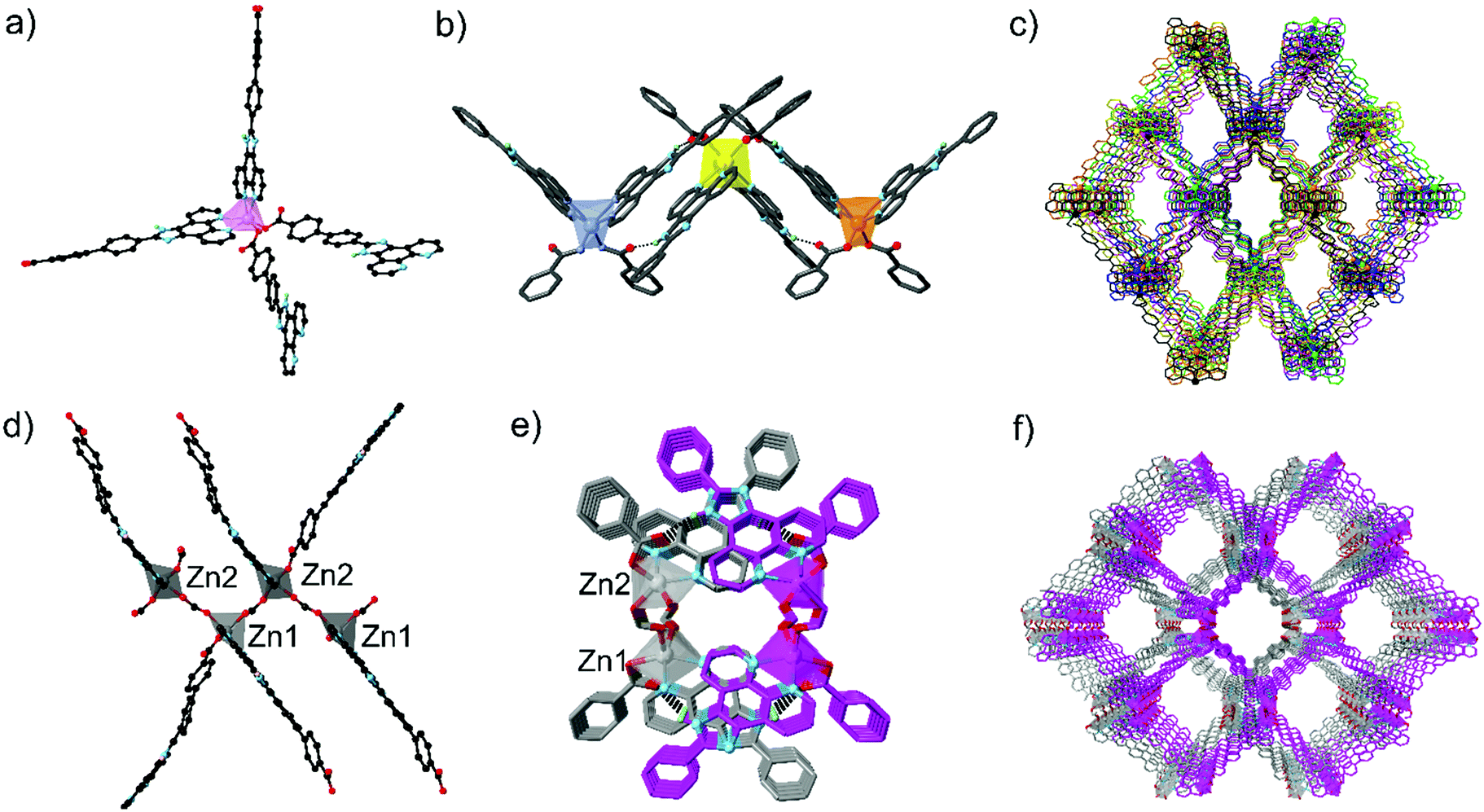 | ||
| Fig. 1 (a and d) Coordination environment around the Mn centre of [Mn(NCPP)2]n (1) and the two unique Zn centres of [Zn2(NCPP)(κ1-O(NCPP))(μ-O2CH)2]n (2), respectively; (b and e) imidazole to free carboxylate oxygen N–H⋯O hydrogen bonding between interpenetrated nets for 1 and 2, respectively, viewed along the a axis for 1 and b axis for 2; (c and f) the extended structures of 1 and 2 respectively, as viewed down the crystallographic a axes. The interpenetrated nets are identified through multiple colour assignments. Colour code: Mn: light pink (figure b; livid yellow and orange represent Mn centres from interpenetrating nets), Zn: grey, (figure e; grey and pink represent Zn centres from interpenetrating nets); black: carbon, lime: hydrogen, red: oxygen, blue: nitrogen. | ||
This coordination environment can be considered as pseudotetrahedral if each chelating phenanthroline moiety is considered as one connecting point. This configuration leads to a 3D diamondoid network, with the overall structure containing six such nets interpenetrating (Fig. S1 and S4, ESI†). Despite vast interpenetration, the structure contains large, 1D channels propagating down the a axis, giving pores of 7.2 × 12 Å. Along each column of Mn clusters aligned parallel to the a axis, adjacent Mn centres are linked together by NCPP− ligands with an Mn⋯Mn distance of 9.70 Å. Close π–π and N–H⋯π interactions exist between the phenanthroline moieties from adjacent units. In addition, close N–H⋯O hydrogen bonds (2.695(5) Å) between the NH from the imidazole ring and the uncoordinated carboxylate oxygen atom further promote network interpenetration (Table S2, ESI†). Phase purity of the bulk yellow crystals was confirmed via powder X-ray diffraction (PXRD) (Fig. S1, ESI†). The thermostability of 1 was established via thermogravimetric analysis (TGA) under N2 and revealed that the MOF exhibits three decomposition steps, at 180, 220 and 380 °C (Fig. S3, ESI†).
A solvothermal reaction between Zn(NO3)2·6H2O, HNCPP, and formic acid as modulator, in DMF at 100 °C, afforded yellow-orange needle crystals suitable for SCXRD. Structural analysis revealed the crystals to be [Zn2(NCPP)(κ1-O(NCPP))(μ-O2CH)2]n (2), crystallizing in the orthorhombic space group Pna21 with an asymmetric unit consisting of two NCPP− ligands, two crystallographically distinct Zn ions and two formate bridges (Fig. 1). Each Zn is coordinated by one chelating phenanthroline moiety, one monodentate carboxylate and two formate ligands, giving an overall pseudotetrahedral geometry. Zigzag zinc formate chains propagate, down the a axis, with each unique zinc atom being connected to two others through two bridging formate linkers. These chains are then crosslinked by the NCPP− ligands, creating an overall 3D network with 4-connected metal nodes and zst21 topology (Fig. S4, ESI†).
There are close π–π interactions (3.08–4.06 Å) between the phenanthroline and the phenylcarboxylate moieties on each zinc centre. The overall structure consists of two interpenetrated nets, which are held in place by close N–H⋯O hydrogen bonds (2.76–2.86 Å) between the uncoordinated carboxylate oxygen atom and the imidazole NH (Table S3, ESI†). syn-Parallel π–π stacking between the imidazole groups from adjacent nets further stabilise the interpenetrated structure.22
2 contains large 1D channels propagating along the a axis, with pore dimensions of 15.3 × 20.6 Å and one edge lined with imidazole nitrogen atoms. Bulk phase purity was confirmed by PXRD (Fig. S2, ESI†) while TGA under N2 (Fig. S3, ESI†) reveals a two-step decomposition pathway at 220 and 325 °C.
The surface areas, total pore volumes and propensity for 1 and 2 to adsorb CO2 was investigated using gas adsorption techniques. Activation of 1 was performed by washing the MOF with DMF, followed by cyclohexane exchange and evacuation at 80 °C. The Brunauer–Emmett–Teller (BET) surface area was determined to be 857 m2 g−1 using N2 isothermal data recorded at 77 K (Fig. S5, ESI†). The isotherms also exhibit a small adsorption step at very low pressure (0.0035 P/P0), alluding to flexibility between interpenetrated nets in the structure (Fig. S6, ESI†).23 A pore size of 11.8 Å was calculated from the N2 adsorption isotherm at 77 K and P/P0 = 0.995 (Fig. S10, ESI†). Activation of 2 was performed by washing the MOF in DMF, followed by DCM exchange and evacuation at 100 °C. The N2 adsorption isotherm performed at 77 K revealed a BET surface area of 940 cm2 g−1 and a pore size of 12.7 Å (Fig. S7 and S11, ESI†).
Gas sorption capabilities were further investigated through recording CO2 adsorption isotherms and calculating the enthalpy of adsorption using the Clausius–Clapeyron method. CO2 uptake at 100 kPa at 273 K, 288 K and 298 K for 1 was 37 cm3 g−1, 22.5 cm3 g−1 and 13 cm3 g−1, respectively, resulting in a zero-coverage enthalpy of adsorption of 31 kJ mol−1 (Fig. S8, ESI†). For 2, CO2 uptake at 273 K and 298 K was 17 and 12.5 cm3 g−1 respectively, giving a zero-coverage enthalpy of adsorption of 19 kJ mol−1 (Fig. S9, ESI†). All CO2 isotherms exhibited a typical type I shape and displayed an adsorption/desorption hysteresis, more pronounced at lower temperatures. We attribute this hysteresis to attractive interactions between the CO2 guest and the conjugated phenyl systems lining the pore walls. Duplication experiments show that this hysteresis was not an effect of short equilibration times while running the experiments.
To further elucidate the presence of strong interactions between the CO2 molecules and the framework atoms, density functional theory calculations, including dispersion corrections, (DFT-D3) were performed to calculate the binding energies and identify the most favourable adsorption site. Both MOFs revealed similar binding energies for CO2 of ca. 31 kJ mol−1, which can be understood through close examination of the favourable adsorption site of each CO2 in the framework. DFT-D3 calculations for 1 show this site to be in tight void spaces created by back-to-back carboxy-phenyl rings running along the c axis of the MOF (Fig. 2b), creating an overall largest cavity diameter (LCD) of 7.3 Å. Close π⋯O![[double bond, length as m-dash]](https://www.rsc.org/images/entities/char_e001.gif) CO interactions are present between the NCPP phenyl rings and the guest CO2 within the range of 2.77–3.64 Å. This denotes 1 as an exceptional candidate for CO2 sorption from flue gas according to recent idealised criteria. This identifies materials with a Qst > 30 kJ mol−1, LCD of 5–7.5 Å and surface area <1000 m2 g−1.24 DFT-D3 calculations for 2 show CO2 to be nestled between the biphenyl NCPP tails of two interpenetrating nets, which have an LCD of 6.7 Å, causing close π⋯OCO interactions (Fig. S12, ESI†). These close interactions also pose 2 to be an excellent candidate for selective CO2 sorption.
CO interactions are present between the NCPP phenyl rings and the guest CO2 within the range of 2.77–3.64 Å. This denotes 1 as an exceptional candidate for CO2 sorption from flue gas according to recent idealised criteria. This identifies materials with a Qst > 30 kJ mol−1, LCD of 5–7.5 Å and surface area <1000 m2 g−1.24 DFT-D3 calculations for 2 show CO2 to be nestled between the biphenyl NCPP tails of two interpenetrating nets, which have an LCD of 6.7 Å, causing close π⋯OCO interactions (Fig. S12, ESI†). These close interactions also pose 2 to be an excellent candidate for selective CO2 sorption.
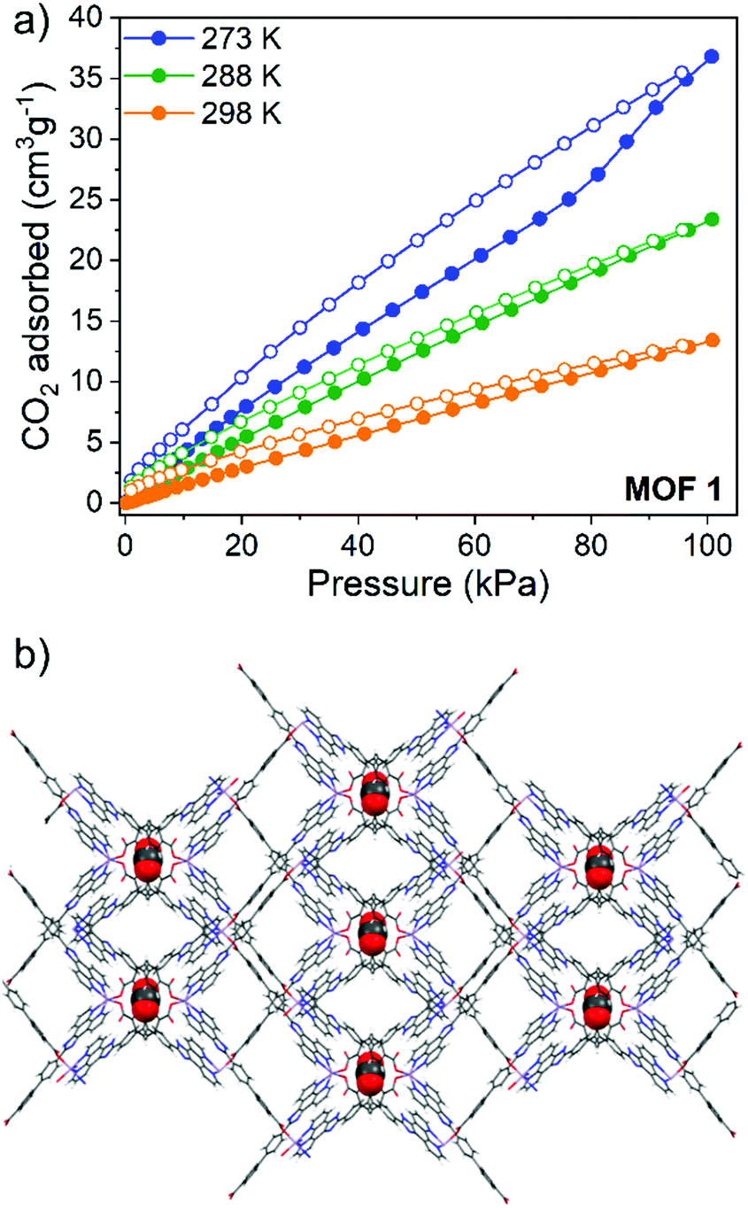 | ||
| Fig. 2 (a) CO2 adsorption (filled circles) and desorption (open circles) isotherms for 1 and (b) DFT-D3 optimization showing the preferential site of adsorption of CO2 in 1. | ||
The employment of a photoactive linker prompted further investigation into the photophysical properties of 1 and 2 through examination using UV-visible absorption spectroscopy and time-correlated single photon counting (TCSPC). Due to the excellent stability of both 1 and 2 in DMF and the instability of 1 in moisture, measurements were made as suspensions in DMF. The absorption maxima (λmax) for the free HNCPP molecule was at 434 nm and assigned to an intra-ligand π → π* transition (Fig. 3a). The similar λmax between HNCPP and the MOFs suggests that deprotonation and coordination to the metal centre has little effect on the excitation energy of the linker. Nevertheless, the coordination of NCPP− to ZnII and MnII has slightly different effects on the absorption spectrum of the ligand. A slight red shift relative to the HNCPP maxima is observed in the absorption of 1 and 2 (λmax = 443 and 439 nm, respectively). This can be attributed to the framework structure hindering π–π stacking in 1 and 2. The absorption spectra of 1 also shows an extra absorption peak at λmax = 416 nm. This is ascribed to the LMCT between the NCPP− ligand and the MnII centre based on previous research using HNCP linkers.19
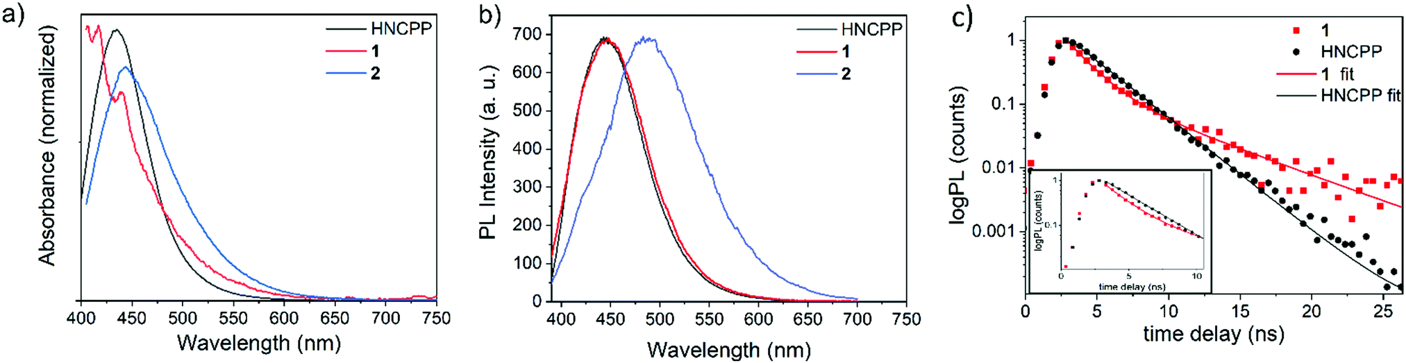 | ||
| Fig. 3 Optical characterisation (a) absorption and (b) steady-state PL spectra of HNCPP, 1 and 2. (c) Time-correlated single photon counting decays of HNCPP and 1. | ||
TCSPC decays for both HNCPP and 1 were recorded in DMF at λemis = 450 nm and highlight the reduced decay lifetime of 1. 2 was not studied as the MOF included formate co-linkers and aggregated during the steady state PL measurement, therefore complicating a direct comparison with the HNCPP linker and 1 (Fig. 3b). Preliminary TCSPC experiments were first performed on the HNCPP ligand in DCM and DMF to accurately determine the correct solvent medium (Fig. S13, ESI†). In DCM, the HNCPP showed a rapid lifetime decay which was improved when the solution was diluted by a factor of 10. Nevertheless, DMF was selected as the solvent medium as DCM exhibited extensive noise levels due to ligand aggregation.
The DMF ligand solution shows a monoexponential decay with a lifetime of 2.44 ns (Fig. 3c). Photoluminescent (PL) decay, as measured by TCSPC, shows a quenching of NCPP lifetime upon coordination to MnII ions in 1. The quenching effect in the MOF indicated electron/energy transfer processes occurring throughout the framework structure. The PL lifetime of 1 is biexponential with decay lifetime components of 1.55 ns, attributed to the LMCT decay, followed by 5.30 ns. This longer, step of PL decay is a process with a magnitude much lower than the fast quenching component. This step could be due to aggregation of luminophores25 or the formation of long-lived triplets due to intersystem crossing facilitated by the metal centres in the MOF.26 To a first approximation, the PL lifetime gives a quenching of 35% compared to the PL lifetime of the ligand.
In conclusion, MOFs constructed from the HNCPP linker and MnII or ZnII result in frameworks with large pore apertures and accessible 1D channels. Of significant interest are the photophysical properties of 1, which exhibits rapid electron transfer between the NCPP− ligand and the MnII centre. Both 1 and 2 display varying degrees of network interpenetration, providing a scaffold for strong interactions with CO2 molecules. DFT-D3 investigations further highlight 1 and 2 as prime CO2 selective candidates. These characteristics, combined with the photoactivity of 1, frames future investigation into NCPP MOFs for photocatalytic CO2 reduction.
We thank S. G. Telfer and C. Forsyth for their assistance. Part of this research was undertaken using the MX2 beamline at the Australian Synchrotron, part of ANSTO, and made use of the ACRF detector. R. B. acknowledges the National Computing Infrastructure and Pawsey supercomputing facilities for the Computational Resources. W. S. acknowledges SFI (13/IA/1896) and the ERC (Supramol CoG 2014-647719).
Conflicts of interest
There are no conflicts to declare.Notes and references
- Z. Ji, H. Wang, S. Canossa, S. Wuttke and O. M. Yaghi, Adv. Funct. Mater., 2020, 2000238 CrossRef CAS.
- A. Schneemann, V. Bon, I. Schwedler, I. Senkovska, S. Kaskel and R. A. Fischer, Chem. Soc. Rev., 2014, 43, 6062 RSC.
- L. K. Macreadie, R. Babarao, C. J. Setter, S. J. Lee, O. T. Qazvini, A. J. Seeber, J. Tsanaktsidis, S. G. Telfer, S. R. Batten and M. R. Hill, Angew. Chem., Int. Ed., 2020, 59, 6090 CrossRef CAS.
- L. K. Macreadie, E. J. Mensforth, R. Babarao, K. Konstas, S. G. Telfer, C. M. Doherty, J. Tsanaktsidis, S. R. Batten and M. R. Hill, J. Am. Chem. Soc., 2019, 141, 3828 CrossRef CAS.
- G. Mínguez Espallargas and E. Coronado, Chem. Soc. Rev., 2018, 47, 533 RSC.
- W. P. Lustig, S. Mukherjee, N. D. Rudd, A. V. Desai, J. Li and S. K. Ghosh, Chem. Soc. Rev., 2017, 46, 3242 RSC.
- E. A. Dolgopolova, A. M. Rice, C. R. Martin and N. B. Shustova, Chem. Soc. Rev., 2018, 47, 4710 RSC.
- M.-L. Hu, S. A. A. Razavi, M. Piroozzadeh and A. Morsali, Inorg. Chem. Front., 2020, 7, 1598 RSC.
- T. Zhang and W. Lin, Chem. Soc. Rev., 2014, 43, 5982 RSC.
- Z.-H. Yan, M.-H. Du, J. Liu, S. Jin, C. Wang, G.-L. Zhuang, X.-J. Kong, L.-S. Long and L.-S. Zheng, Nat. Commun., 2018, 9, 3353 CrossRef.
- V. Stavila, A. A. Talin and M. D. Allendorf, Chem. Soc. Rev., 2014, 43, 5994 RSC.
- P. Samanta, S. Let, W. Mandal, S. Dutta and S. K. Ghosh, Inorg. Chem. Front., 2020, 7, 1801 RSC.
- H.-Q. Yin and X.-B. Yin, Acc. Chem. Res., 2020, 53, 485 CrossRef CAS.
- S. Zhang, Y. Yang, Z.-Q. Xia, X.-Y. Liu, Q. Yang, Q. Wei, G. Xie, S.-P. Chen and S.-L. Gao, Inorg. Chem., 2014, 53, 10952 CrossRef CAS.
- H.-Y. Sun, C.-B. Liu, Y. Cong, M.-H. Yu, H.-Y. Bai and G.-B. Che, Inorg. Chem. Commun., 2013, 35, 130 CrossRef CAS.
- W. Xu, Y.-J. Tang, L.-Q. Zheng, J.-M. Xu, J.-Z. Wu, Y.-C. Ou and M.-L. Tong, Inorg. Chem., 2019, 58, 13766 CrossRef CAS.
- G. Accorsi, A. Listorti, K. Yoosaf and N. Armaroli, Chem. Soc. Rev., 2009, 38, 1690 RSC.
- X. Zhou, J.-L. Peng, C.-Y. Wen, Z.-Y. Liu, X.-H. Wang, J.-Z. Wu and Y.-C. Ou, CrystEngComm, 2017, 19, 6533 RSC.
- L. Martins, L. K. Macreadie, D. Sensharma, S. Vaesen, X. Zhang, J. J. Gough, M. O'Doherty, N.-Y. Zhu, M. Rüther, J. E. O'Brien, A. L. Bradley and W. Schmitt, Chem. Commun., 2019, 55, 5013 RSC.
- S. Saxer, C. Marestin, R. Mercier and J. Dupuy, Polym. Chem., 2018, 9, 1927 RSC.
- M. O’Keeffe, M. A. Peskov, S. J. Ramsden and O. M. Yaghi, Acc. Chem. Res., 2008, 41, 1782 CrossRef.
- S. Ray and A. Das, J. Mol. Struct., 2015, 1089, 146 CrossRef CAS.
- X. Sun, Y. Ma, J. Zhao, D.-S. Li, G. Li, L. Zhang and Y. Liu, Dalton Trans., 2018, 47, 13158 RSC.
- C. Altintas, G. Avci, H. Daglar, A. Nemati Vesali Azar, S. Velioglu, I. Erucar and S. Keskin, ACS Appl. Mater. Interfaces, 2018, 10, 17257 CrossRef CAS.
- J. Mei, Y. Hong, J. W. Y. Lam, A. Qin, Y. Tang and B. Z. Tang, Adv. Mater., 2014, 26, 5429 CrossRef CAS.
- J. Calbo, M. J. Golomb and A. Walsh, J. Mater. Chem. A, 2019, 7, 16571 RSC.
Footnote |
| † Electronic supplementary information (ESI) available: TGA, PXRD, isotherm data, isosteric heat of adsorption, BET calculations and DFT-D3 calculations. CCDC 2010335 and 2010336. For ESI and crystallographic data in CIF or other electronic format see DOI: 10.1039/d0cc05715k |
| This journal is © The Royal Society of Chemistry 2020 |