 Open Access Article
Creative Commons Attribution 3.0 Unported Licence
Integrated plug flow synthesis and crystallisation of pyrazinamide†
C. Daniel
Scott
a,
Ricardo
Labes
 b,
Martin
Depardieu
c,
Claudio
Battilocchio‡
 b,
Matthew G.
Davidson
a,
Steven V.
Ley
 b,
Chick C.
Wilson
ad and
Karen
Robertson
 *c
*c
aCentre for Sustainable Chemical Technologies, Department of Chemistry, University of Bath, UK
bDepartment of Chemistry, University of Cambridge, UK
cDepartment of Chemistry, University of Bath, UK. E-mail: K.Robertson@bath.ac.uk
dEPSRC Future Continuous Manufacturing and Advanced Crystallisation Research Hub, University of Bath, UK
First published on 10th July 2018
Abstract
We report the integration of flow chemistry with plug flow crystallisation. Catalytic flow hydration of pyrazinecarbonitrile to pyrazinamide was performed in a packed bed column of MnO2. The effluent of this flow reactor was directly linked to a tri-segmented tubular crystalliser (KRAIC), providing a seamless transition from flow synthesis to crystallisation, with control over solid form and particle characteristics.
Flow chemistry and crystallisation techniques offer higher levels of control over the resultant products and routes to leaner and more efficient manufacturing.1,2 Due to the difference in design needs for flow reactors for solution-based synthesis and crystallisation, the rates of production from these reactors are often incompatible. Flow chemistry achieves a high level of control and process intensification through exploiting reactors with internal diameters (IDs) of commonly of less than 2 mm in the research environment.3–5 These IDs are incompatible with most crystallising solutions as they can lead to blockages as the crystallising particles form. The larger ID flow crystallisers (2.5–8 mm) that are more typical for this downstream process use alternative mechanisms to exact control over the crystallising solution which typically requires significantly higher flow rates than achievable in flow chemistry apparatus.2,6,7 As a result of this, current examples of coupled flow chemistry and crystallisation have tended to employ cascade/continuous stirred tank reactors (CSTRs); these can operate at a wider range of flow rates as mixing is not related to the flow rate but imparted through impellers.8
Crystallisation in CSTRs can enable seamless continuous operation as presented by Braatz et al.,9 for example, but can only approach the often desired plug flow operation through an impractically long series of STRs. Nagy et al. recently reported the successful coupling of a microfluidic chip and air-segmented tubular crystalliser set-up for the telescoped synthesis and crystallisation of diphenylhydramine.10 Due to fouling issues experienced the yield of this process was low (max. synthetic yield, 34.4%, solid yield not reported). We have developed a novel tubular flow crystallisation system that offers a potentially improved set-up for coupling to flow chemistry outputs. This employs tri-segmented flow (segmenting the solution with air and an immiscible carrier fluid).11,12 This approach inherently imparts plug flow (through physical separation of solution droplets) and decouples the solution flow rate from the net flow rate, enabling a slower solution flow without cost to the mixing intensity.
We have also previously reported a mild and highly efficient flow synthesis for pyrazinamide, a compound used to treat tuberculosis (Fig. 1).13,14 The reported method achieved clean conversion to the product in high chemical yields. In this communication we report the high yielding plug flow coupling of this chemistry with crystallisation techniques for the preparation and crystallisation of pyrazinamide with a residence time (RT) of 32 min 17 s. Solid form (polymorph) selectivity has also been achieved in the integrated process, a vital consideration in prospective end-to-end process design for solid state materials such as pharmaceuticals. The direct coupling of flow synthesis and crystallisation of pyrazinamide has resulted in a high yield of pure micro-sized product, coupled with polymorph selectivity in the solid form obtained, which is thus applicable for immediate incorporation into drug formulation.
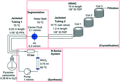
Representations of the set-up can be seen in Fig. 2 and 3 (schematic and actual, respectively). Full experimental details are available in the ESI.† Coupling of the flow preparation of pyrazinamide from pyrazinecarbonitrile (catalytic hydration via a packed bed column of MnO2 at 80 °C) and subsequent crystallisation was achieved through connection of the effluent of the packed bed column to the segmentation unit after the back-pressure regulator (BPR, 12 bar) as shown in Fig. 2. The three immiscible phases (solution, air and carrier fluid) were segmented in a cross-piece mixer (thru-hole, 1.25 mm) which was actively heated to maintain dissolution of the pyrazinamide. In initial experiments (hereafter termed ‘uncontrolled nucleation runs’), the tri-segmented flow then passed directly into 15 m of air-cooled 1/8′′ ID FEP tubing prior to separation of the carrier fluid (perfluoropolyether, Galden SV 110) and online filtration. The maximum crystal length obtained in these experiments (2.4 mm) approaches the internal diameter of the tubing and agglomeration of crystals within a slug resulted in blockages within the tubing. Subsequent experiments (hereafter referred to as ‘controlled nucleation runs’) therefore employed a 1.2 m section of tubing prior to the main crystalliser body which was cooled to 10 °C. This resulted in the formation of a greater number of nuclei than is achievable with a slower cooling gradient, minimising the resultant crystallite size and preventing blockages. Table 1 details the differences between the controlled and uncontrolled nucleation runs.
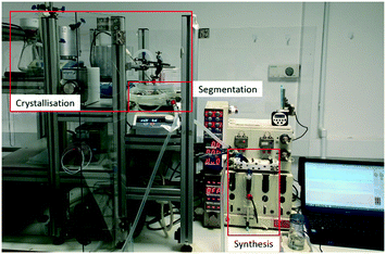 | ||
| Fig. 3 View of integrated flow synthesis and crystallisation apparatus with the synthesis, segmentation and crystallisation sections highlighted. | ||
| Uncontrolled nucleation runs | Controlled nucleation runs | |
|---|---|---|
| Crystal size (major axis, mm) | 1.02 | 0.1 |
| Synthesis RT (min) | 4 min 7 s | 4 min 7 s |
| Crystallisation RT (min) | 16.25 | 28.17 |
| Total RT (min) | 20.38 | 32.28 |
| Crystallisation onset (m, min, °C) | 8.69, 9.4, 19.3 | 0.53, 2.5, 11.4 |
| Yield | >2% | 53% |
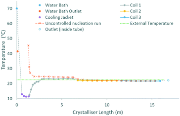
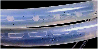
The cooling gradients achieved in the KRAIC during the crystallisation of pyrazinamide are shown in Fig. 4. In the controlled nucleation runs, the set temperature of the tubing jacket is achieved rapidly within the solution slugs (as measured internally) but the reduced heat transfer efficiency between liquid and gas15 results in a higher temperature for the air slugs. As the carrier fluid creates a barrier between the solution and air slugs, this has a minimal effect on the solution slugs during active temperature control within the tubing jacket. This resulted in the promotion of nucleation and crystal growth within this region as shown in Fig. 5 (a video is available in the ESI†). After the active temperature controlled region, a rapid increase to room temperature is observed in coil 1. Coils 2 and 3 provide a cooling effect (the intensity of which reduces over length) due to heat dissipation through the heat conductive aluminium coil housing, resulting in a final temperature 1 °C below room temperature.
In the uncontrolled nucleation runs, the glass housing of coil 1 enables a steady temperature reduction after initial rapid heat loss upon emergence from active temperature control (water bath for the segmentation unit). The same heat sink effect seen for the controlled nucleation runs is seen at the start of the first aluminium coil holder, resulting in a rapid coalescence of the temperature within the uncontrolled nucleation run with respect to the controlled nucleation run.
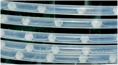
The average slug volume was 0.075 ml (Fig. 6, see ESI† for details) with an aspect ratio of 1![[thin space (1/6-em)]](https://www.rsc.org/images/entities/char_2009.gif) :
:![[thin space (1/6-em)]](https://www.rsc.org/images/entities/char_2009.gif) 1.08 (2.94 × 3.2 mm). This ensures a high expression of plug flow behaviour with excellent mixing homogeneity.
1.08 (2.94 × 3.2 mm). This ensures a high expression of plug flow behaviour with excellent mixing homogeneity.
From a controlled crystallisation run, total RT of 32 min 17 s, a yield of 53% of pure pyrazinamide crystals was achieved during a 1 h run without any blocking/fouling issues. The resultant needle crystals (shown in Fig. 7) have an average particle size of 100 μm (in the major axis, 5 μm in the minor axis).
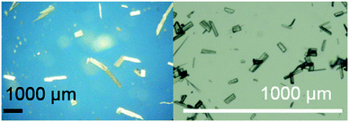 | ||
| Fig. 7 Microscope images of pyrazinamide crystals obtained from uncontrolled nucleation (left) and controlled nucleation (right) runs. | ||
It was not possible to obtain a representative yield and RT in uncontrolled nucleation runs due to blocking issues. A faster flow rate of 9.36 ml min−1 (16 min 16 s RT excl. blockage removal time) was employed to mitigate blocking with limited success. Fig. 7 shows the crystals obtained from an uncontrolled and controlled nucleation run, the average particle size (Table 1) is 10× greater for the uncontrolled nucleation runs despite the shorter crystallisation time with respect to the controlled crystallisation runs.
As for many molecular materials of interest in, for example, the pharmaceutical industry, pyrazinamide is polymorphic. The solid form obtained, and its selectivity, is a vital consideration for crystallisation process development within overall production process design. Pure γ-pyrazinamide was obtained from controlled and uncontrolled nucleation runs where blockage events were minimised (ESI;† Fig. S7 and S8). This polymorphic form is normally obtained from melt16,17 or sublimation17,18 crystallisation and previously reported solution-based crystallisation of pure γ-pyrazinamide has exclusively involved non-aqueous solvents/solvent mixtures.17 The expected polymorphic form for a cooling crystallisation of a supersaturated aqueous solution is α-pyrazinamide.18 We have previously shown that the tri-segmented environment within the KRAIC crystalliser can result in the production of unexpected polymorphs.11 This is a likely consequence of the fact that there are no solid–liquid boundaries present during nucleation. In uncontrolled nucleation runs where blockages were not removed prior to wall-influenced crystallisation, a mixture of α- and γ-pyrazinamide was recovered, supporting this theory.
The system chosen here was crystallised from the same solvent system in which it was synthesised. This enabled facile coupling, however in-line extractors to change a solvent system have been developed in our labs to broaden the range of inline crystallisation capabilities.19,20 Such extractors also enable the compatibility of more dilute syntheses with integrated crystallisation.
Conclusions
This work constitutes a novel research laboratory scale coupling of the chemical flow preparation of a drug substance pyrazinamide with integrated in-line crystallisation. By decoupling the flow synthesis and flow crystallisation flow rates, the advantages of both are maintained. Improved processing of needle crystals in flow crystallisation was achieved through controlled nucleation techniques, with control over the solid form polymorph obtained. This resulted in micro-sized particles which can be directly incorporated into formulation without further processing.The range of milli-scale flow crystallisers, which have been developed in the last few years, is encouraging and provides a wide scope for direct integration of flow synthesis and crystallisation.21–23 On the other hand, there are still limitations for integrating synthesis and crystallisation, e.g. microfluidic synthesis procedures may yet not be compatible with the necessarily milli-fluidic size of crystallisers designed for resultant crystals greater than ca. 100 μm. As in all flow cooling crystallisation techniques, wide metastable zone widths and long induction times can be problematic. In addition to the forced cooling solution presented here, alternatives like anti-solvent crystallisation techniques24 can address some of those challenges. There are still opportunities for continued development in the field, which should provide tools for engineering crystallisation and its coupling with synthesis systems.
Conflicts of interest
The authors state that there are no conflicts to declare.Acknowledgements
The authors would like to acknowledge the EPSRC Centre for Doctoral Training in Sustainable Chemical Technologies (EP/L016354/1, Davidson, Scott) for funding and Miss Pollyanna Payne for her support during this work. At Cambridge we acknowledge the EPSRC (EP/K009494/1 and EP/K039520/1) for support (Ley).Notes and references
- A. Kirschning, L. Kupracz and J. Hartwig, Chem. Lett., 2012, 41, 562–570 CrossRef.
- A. J. Alvarez and A. S. Myerson, Cryst. Growth Des., 2010, 10, 2219–2228 CrossRef.
- B. Musio, E. Gala and S. V. Ley, ACS Sustainable Chem. Eng., 2018, 6, 1489–1495 CrossRef.
- D. T. McQuade and P. H. Seeberger, J. Org. Chem., 2013, 78, 6384–6389 CrossRef PubMed.
- M. Baumann, I. R. Baxendale, P. Filipponi and T. Hu, Org. Process Res. Dev., 2017, 21, 2052–2059 CrossRef.
- T. McGlone, N. E. B. Briggs, C. A. Clark, C. J. Brown, J. Sefcik and A. J. Florence, Org. Process Res. Dev., 2015, 19, 1186–1202 CrossRef.
- A.-T. Nguyen, Y. L. Joo and W.-S. Kim, Cryst. Growth Des., 2012, 12, 2780–2788 CrossRef.
- K. A. Powell, A. N. Saleemi, C. D. Rielly and Z. K. Nagy, Chem. Eng. Process., 2015, 97, 195–212 CrossRef.
- S. Mascia, P. L. Heider, H. T. Zhang, R. Lakerveld, B. Benyahia, P. I. Barton, R. D. Braatz, C. L. Cooney, J. M. B. Evans, T. F. Jamison, K. F. Jensen, A. S. Myerson and B. L. Trout, Angew. Chem., Int. Ed., 2013, 52, 12359–12363 CrossRef PubMed.
- B. P. Loren, M. Wleklinski, A. Koswara, K. Yammine, Y. Y. Hu, Z. K. Nagy, D. H. Thompson and R. G. Cooks, Chem. Sci., 2017, 8, 4363–4370 RSC.
- K. Robertson, P.-B. Flandrin, A. R. Klapwijk and C. C. Wilson, Cryst. Growth Des., 2016, 16, 4759–4764 CrossRef.
- K. Robertson, P. B. Flandrin, H. J. Shepherd and C. C. Wilson, Chim. Oggi, 2017, 35, 19–22 Search PubMed.
- C. Battilocchio, J. M. Hawkins and S. V. Ley, Org. Lett., 2014, 16, 1060–1063 CrossRef PubMed.
- C. Battilocchio, S. H. Lau, J. M. Hawkins and S. V. Ley, Org. Synth., 2017, 94, 34–45 CrossRef.
- P. A. Walsh, E. J. Walsh and Y. S. Muzychka, Int. J. Heat Mass Transfer, 2010, 53, 3193–3201 CrossRef.
- G. Thomas and M. C. Huffstutler, Acta Crystallogr., 1961, 14, 693–694 CrossRef.
- S. Cherukuvada, R. Thakuria and A. Nangia, Cryst. Growth Des., 2010, 10, 3931–3941 CrossRef.
- R. A. E. Castro, T. M. R. Maria, A. O. L. Evora, J. C. Feiteira, M. R. Silva, A. M. Beja, J. Canotilho and M. E. S. Eusebio, Cryst. Growth Des., 2010, 10, 274–282 CrossRef.
- D. E. Fitzpatrick and S. V. Ley, React. Chem. Eng., 2016, 1, 629–635 RSC.
- M. O'Brien, P. Koos, D. L. Browne and S. V. Ley, Org. Biomol. Chem., 2012, 10, 7031–7036 RSC.
- M. Jiang, C. D. Papageorgiou, J. Waetzig, A. Hardy, M. Langston and R. D. Braatz, Cryst. Growth Des., 2015, 15, 2486–2492 CrossRef.
- L. N. Ejim, S. Yerdelen, T. McGlone, I. Onyemelukwe, B. Johnston, A. J. Florence and N. M. Reis, Chem. Eng. J., 2017, 308, 669–682 CrossRef.
- M. Romano, C. Pradere, F. Sarrazin, J. Toutain and J. C. Batsale, Chem. Eng. J., 2015, 273, 325–332 CrossRef.
- A. Yashina, F. Meldrum and A. deMello, Biomicrofluidics, 2012, 6, 022001 CrossRef PubMed.
Footnotes |
| † Electronic supplementary information (ESI) available: Videos of tri-segmented slugs in the crystalliser, full experimental and analytical details are available. See DOI: 10.1039/c8re00087e |
| ‡ Current address: Syngenta Crop Protection, Process Research, Schaffhauserstrasse 101, CH-4332, Switzerland. |
| This journal is © The Royal Society of Chemistry 2018 |


