 Open Access Article
Creative Commons Attribution 3.0 Unported Licence
Metal–organic frameworks as competitive materials for non-linear optics
L. R.
Mingabudinova
a,
V. V.
Vinogradov
a,
V. A.
Milichko
a,
E.
Hey-Hawkins
*b and
A. V.
Vinogradov
*a
aITMO University, St. Petersburg, 197101, Russian Federation. E-mail: avv@scamt.ru
bLeipzig University, Faculty of Chemistry and Mineralogy, Institute of Inorganic Chemistry, D-04103 Leipzig, Germany. E-mail: hey@uni-leipzig.de
First published on 20th September 2016
Abstract
The last five years have witnessed a huge breakthrough in the creation and the study of the properties of a new class of compounds – metamaterials. The next stage of this technological revolution will be the development of active, controllable, and non-linear metamaterials, surpassing natural media as platforms for optical data processing and quantum information applications. However, scientists are constantly faced with the need to find new methods that can ensure the formation of quantum and non-linear metamaterials with higher resolution. One such method of producing metamaterials in the future, which will provide scalability and availability, is chemical synthesis. Meanwhile, the chemical synthesis of organized 3D structures with a period of a few nanometers and a size of up to a few millimeters is not an easy task and is yet to be resolved. The most promising avenue seems to be the use of highly porous structures based on metal–organic frameworks that have demonstrated their unique properties in the field of non-linear optics (NLO) over the past three years. Thus, the aim of this review is to examine current progress and the possibilities of using metal–organic frameworks in the field of non-linear optics as chemically obtained metamaterials of the future. The review begins by presenting the theoretical principles of physical phenomena represented by mathematical descriptions for clarity. Major attention is paid to the second harmonic generation (SHG) effect. In this section we compare inorganic single crystals, which are most commonly used to study the effect in question, to organic materials, which also possess the required properties. Based on these data, we present a rationale for the possibility of studying the non-linear optical properties of metal–organic structures as well as describing the use of synthetic approaches and the difficulties associated with them. The second part of the review explicitly acquaints the reader with a new class of materials which successfully combines the positive properties of organic and inorganic materials. Using recently synthesized metal–organic frameworks and coordination polymers in the field of non-linear optics as an example, we consider synthetic approaches used for obtaining materials with desired properties and the factors to be considered in this case. Finally, probable trends towards improving the quality of the synthesized materials with regards to their further use in the field of non-linear optical effects are described.
1. Introduction
1.1 A brief introduction to non-linear optics
Before proceeding to the consideration of current trends in the field of materials used for non-linear optics, one should be familiar with the existing theoretical propositions in order to have an understanding of the processes observed in the studies of the corresponding effects.When considering the interaction of a light wave with matter, we introduce the polarization vector P, which is a function of the strength of the electric field of the light wave: P = f(E). At a time when studying the interaction of radiation with matter involved light sources with a small capacity and providing an intensity of the order of 1–10 W cm−2 and achievable light fields of 0.1–10 V cm−1 as a result, it was believed that the investigated experimental characteristics did not depend on the radiation intensity. The proposed assertion can be attributed to the field of linear optics, where the dielectric constant ε and the magnetic susceptibility χ are treated as independent of the intensity of electromagnetic waves propagating in the medium, which corresponds to a linear relationship between the polarization vector P and the electric field strength E (Fig. 1(a)).1 However, with the advent of laser sources with an intensity of 1010 W cm−2 and the resulting field of about 107 V cm−1, one cannot neglect an intra-atomic field which is of the order of e/ro2 ∼ 109 V cm−1 (ro is the characteristic radius of an electronic orbital, which is equal to a value of about 10−8 cm).
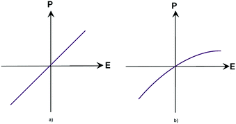 | ||
| Fig. 1 Relationship between the E and P vectors in a linear medium (a) and in a non-linear medium (b). | ||
In such an analysis, an equation relating the electric field strength and polarization can be generally represented by expanding as a series:
| P = κE + χEE + ϑEEE +⋯, |
Changing the degree of intensity and exposure time also affects the change of the light wave field over time E(t) = E0![[thin space (1/6-em)]](https://www.rsc.org/images/entities/char_2009.gif) cos(ωt). The second harmonic originates from the quadratic term χEE of the polarization P expansion in powers of the electric field of the light wave. The material polarization component, which occurs in the second term of the equation, can be expressed as follows:
cos(ωt). The second harmonic originates from the quadratic term χEE of the polarization P expansion in powers of the electric field of the light wave. The material polarization component, which occurs in the second term of the equation, can be expressed as follows:
| P(2) = 1/2ε0(χ(2)E02) + (χ2E02 cos(2ωt)) |
1.2 Phase synchronism conditions
Interaction between light beams (ω1 and ω2) inside matter can result in the generation of beams with a sum (or difference) frequency (ω3). The most effective case when the resulting frequency ω3, attributable to the given element of volume from the preceding elements, corresponds to the desired phase of the radiation at the same frequency generated in this volume element. In this case, the intensity of generation will increase by several orders of magnitude, since the process of accumulation takes place throughout the non-linearity of the medium, which is fulfilled under the conditions of phase (wave and spatial) synchronism between beams' wave vectors:| k1 + k2 = k3, |
Second harmonic generation is a special case of the total frequency generation ω1 + ω2 = ω3, in which waves of the same frequency enter a medium, and the total radiation is ω + ω = 2ω. The conditions of phase synchronism for the case when the wave vectors are collinear can be written in terms of wave numbers as follows:
| Kω + kω = k2ω |
Taking into account the phase synchronism, we obtain nω + nω = 2n2ω. Thus, it is necessary to keep the condition nω = n2ω in a non-linear medium.
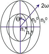
Typically, in media with normal dispersion, such a condition is not fulfilled, since the function n(ω) increases with increasing frequency. There are several ways to overcome it. Among them, the use of crystals with birefringence has the greatest practical importance. In such a crystal, one chooses a propagation direction for which the refractive index of an ordinary ray with the main frequency is equal to the refractive index of an extraordinary ray of the second harmonic. Fig. 2 schematically shows a cross-section of refractive index surfaces (refractive index indicatrix) for a negative uniaxial crystal, i.e. that for which at a given fixed frequency ne < no (Fig. 2). The current values of extraordinary refractive indices (at an arbitrary angle Θ between the wave vector and the optical axis of the crystal) are indicated by the superscript “e”: ne.
There are several classes of crystals lacking a center of symmetry for which n1o|ω = ne2(θ)|2ω in the case of propagation of waves with frequencies ω and 2ω at the angle qc with respect to the optical axis of the crystal. The angle between the optical axis of a non-linear crystal and the wave vectors of the interacting waves is called the phase (wave and spatial) synchronism angle.
As an example of practical application, Fig. 3 demonstrates several configurations for second harmonic generation in bulk materials and in waveguides, in which infrared light is converted into visible light and visible light into ultraviolet radiation.
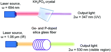 | ||
| Fig. 3 Demonstration of the second harmonic in the visible region using different types of inorganic crystals. Adopted from ref. 1 (Copyright © 2000-2016 by John Wiley & Sons, Inc.). | ||
According to Neumann's principle, the symmetry of a physical property must coincide with the crystal symmetry, so centrosymmetric crystals cannot possess the properties described by polar tensors of odd ranks. Thus, centrosymmetric crystals cannot have pyro- and piezoelectric, linear electrooptical properties, optical activity, etc.
The above fact is used to quickly examine the presence of second harmonic generation upon irradiation with a laser beam. Hence, the existence of the piezoelectric effect and second harmonic generation allows for an unequivocal conclusion that a substance is non-centrosymmetric; if the effect is expected but not observed, then the effect is apparently just too weak.
Observation of electrooptical and magnetooptical effects (dependence of the refractive index on static electric or magnetic fields) corresponds to the case of quadratic non-linearity if one of the fields is permanent. These effects are significant in an important class of photovoltaic and photorefractive effects. For example, in a number of semiconductors the influence of radiation results in a spatial separation of oppositely charged carriers (electrons and holes). This gives rise to an electrostatic field with a change in the permittivity tensor.
One of the major limitations in practical terms is that there are hardware limitations for studying non-linear optical properties of a material. Consequently, for many years research was mainly focused on the measurements of macro-objects as the transition to the micro level was limited by this problem. However, it is the field of micro-objects that will undergo further development of non-linear optics as successfully demonstrated in several studies using synthesized materials as an example. Switching to the said level is also interesting with regards to the fact that it is possible to make an assumption where structural units are largely responsible for the observed effect. In addition to this, it is worth noting that the material should also be resistant to laser radiation within a predetermined range to avoid thermal degradation. Thus, attention should turn to synthetic approaches, which facilitate obtaining the desired structure, and then to techniques for modifying the material to render it suitable for the process of investigation.
1.3 The appearance of NLO in different media
Since the attention of scientists has been focused on investigating various non-linear optical effects, entire classes of materials have been studied. However, it is worth noting that every material has its drawbacks. On the way to obtaining a material devoid of these deficiencies, the attention was shifted to organic materials. However, they also have failed to fully satisfy technical needs due to their high instability. Thus, the present time is characterized by a growing interest in hybrid materials, which successfully combine the properties of both organic and inorganic components.Investigations on non-linear optical properties of the low-temperature modification β-BaB2O4 (BBO) of barium borate started in the 1980s. The lack of a center of symmetry in this crystal provides a number of interesting properties, such as second harmonic generation with high efficiency (approximately 6 times greater than that of potassium dihydrogen phosphate), a high laser damage threshold, and large birefringence.2,3 Single crystals of BBO found applications in optoelectronics for conversion of the laser light frequency according to the mechanism of generation of second and higher harmonics. Electronic delocalization in complex boron–oxygen anions leads to the presence of non-linear optical properties in their single crystals.4–7 The high polarizability of borate crystals caused by the peculiarities of their electronic structure is comparable to the polarizability of organic aromatic compounds.8,9
The nature of the chemical bonds in the system (Fig. 4) is shown for a better understanding of non-linear optical properties in further studies of single crystals using metal–organic frameworks as an example. The sp2 hybridized boron in cyclic anions (Fig. 4a and b) interacts with an oxygen atom, providing a vacant orbital for the filled orbitals of the oxygen atoms, resulting in the formation of a π-bond within the ring. The interaction between the barium cations and borate anions is electrostatic; there is an intermolecular interaction10 between electrically neutral layers.
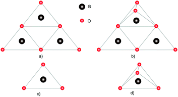 | ||
| Fig. 4 Structural units that make up borate crystals: (a) B3O6, (b) B3O7, (c) BO3, and (d) BO4. Adapted from ref. 10 (with permission from Copyright © Royal Society of Chemistry 2016). | ||
The mechanical properties and resistance to laser radiation present in inorganic crystals are typical of these types of single crystals as well. Single crystals of borates are usually grown using the Czochralski method10 or by direct recrystallization of the cooled melt. However, a tendency towards vitrification significantly complicates the process of growth. Moreover, low yields of suitable materials, undesirable variations in crystal properties, and energy consumption of production processes, ultimately lead to high costs of the finished optical elements.
Another inorganic crystalline compound used in non-linear optics is potassium dihydrogen phosphate, KH2PO4 (KDP). This is a single-axis, negative piezoelectric crystal with the symmetry class ![[4 with combining macron]](https://www.rsc.org/images/entities/char_0034_0304.gif) 2m. Its advantages include high radiation resistance (it is not destroyed when exposed to extremely high intensities of light radiation), relatively low level of absorption in the transparent region, and weak temperature dependence n(T) of the refractive index. However, there is a serious drawback in its practical application: the hygroscopy of the crystals, which requires certain measures when working with this material. Among the second class of inorganic crystals one can distinguish lithium niobate, LiNbO3, another uniaxial negative piezoelectric crystal with the symmetry class 3m and a transparency range of 0.4–5 μm. The refractive indices of the crystal greatly depend on the temperature n(T) of the sample.
2m. Its advantages include high radiation resistance (it is not destroyed when exposed to extremely high intensities of light radiation), relatively low level of absorption in the transparent region, and weak temperature dependence n(T) of the refractive index. However, there is a serious drawback in its practical application: the hygroscopy of the crystals, which requires certain measures when working with this material. Among the second class of inorganic crystals one can distinguish lithium niobate, LiNbO3, another uniaxial negative piezoelectric crystal with the symmetry class 3m and a transparency range of 0.4–5 μm. The refractive indices of the crystal greatly depend on the temperature n(T) of the sample.
This crystal is grown by pulling from the melt. It is resistant to moisture but its linear dimensions with the necessary optical quality are substantially smaller than those of KDP. The radiation resistance is not inferior to the latter.
The quality factor for lithium niobate is higher than that of KDP, but a fairly high temperature dependence of the refractive index n(T) and a slightly higher level of absorption in the transparent region lead to a breach of the phase synchronism conditions. This is due to the rapid heating of the crystal under the action of radiation with extremely high intensity, such as radiation using fusion devices. However, due to this temperature dependence, lithium niobate allows for convenient 90° tangent SHG synchronism for radiation with a wavelength of about 1 μm upon thermostating it at a temperature of 70–90 °C.
The optical quality of the crystals during growth may be impaired as a result of morphological instability, impurity contents, inclusions in the structure (due to the peculiarities of synthesis), viscosity, and tendency to vitrification for some systems.10
At the same time, the processes of growing such crystals are usually difficult and extremely energy intensive. The synthesis is carried out under high vacuum or in an inert atmosphere at a pressure of up to 1700 atm, and also requires a temperature ranging from 600 to 900 °C. In addition, it may take 10 days to 8 weeks to obtain a crystal of the size 20 mm × 20 mm × 60 mm. Moreover, of utmost importance is the fact that these methods do not allow the creation of a new design of structures, thereby limiting their potential use. Additional constraints are imposed due the low stability in the presence of atmospheric moisture.
In organic materials, each molecule should be considered as a separate dipole with non-linear polarization, and if the distance between the molecules is much smaller than the wavelength of the incident light, the volumetric non-linear coefficient can be considered as the sum of dipoles (in non-coherent regime) with some correction (F), taking into account the mutual orientation of the molecules.1 Thus, the bulk values of non-linear coefficients χ(2) and χ(3) can be expressed in terms of corresponding molecular coefficients β and γ. In this case, we obtain expressions in the form:
| χ(2) = NβF and χ(3) = NγF. |
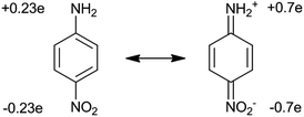 | ||
| Fig. 5 Molecular structures for the ground and excited states and the degree of charge transfer from donor to acceptor in the ground and excited states. | ||
To produce molecules with large values of β, one should select the strongest donor (–NH2, –NMe2) and acceptor (–CN, –NO2) groups and increase the conjugated bond length between molecules. The transition from such dipole molecules to the bulk material with high non-linear polarizability χ(2) is investigated while considering the structure of the material. The problem is that in most cases of crystallization the dipole molecules line up in such a way that their dipole moments are oppositely directed. In this case, the total optical polarizability is close to zero. However, there are several ways to solve this problem. One is to coat thin ordered molecular layers using the Langmuir–Blodgett method, whereby monomolecular layers are applied sequentially so that the dipole moments of the molecules are directed in the same direction.
Scientists have achieved impressive results in this area. However, the creation of materials with directional optical properties remains an extremely difficult task to solve. Therefore, the majority of approaches to the preparation of materials based on chromophores rely purely on the chemical intuition of the researchers. In recent decades, heterocyclic fragments have been considered to be promising for chromophores, in particular as elements for the π conjugation. Moreover, theoretical calculations have already been performed for chromophores possessing one or more thiophene as well as triazole, pyrrole or furan rings.
To achieve high coefficients in non-linear optical properties, an optimal choice of the electron donor/acceptor in the system is necessary, which also poses a challenge for researchers at the moment. In recent years, major attention has been focused on electron bridges in the chromophore structure and the properties of the acceptor with no emphasis on the properties of the donor, although it also affects the final characteristics of the system. The class of alkyl and aryl amines, which have a lone pair of electrons on nitrogen suitable for interacting with the π* orbital of the aromatic ring, turned out to be the most successful for applications. Perhaps this was the reason that prompted scientists to pay attention to the introduction of additional heteroatoms in the fragments of the chromophore donor, which sharply modulates conjugation of the π-electron system and changes the kinetics of charge transfer, affecting in turn the first-order hyperpolarizability of the chromophores. Moreover, the introduction of heteroatoms in the structure allows for further synthetic modification. However, it should be borne in mind that in this case the problem of obtaining a quality product as a result of a multi-stage chemical synthesis still persists.
Examples of such solutions could be provided by the creation of a series of chromophores11 with one or two heteroatoms in the ortho position relative to the π bridge, where more efficiently conjugation of these heteroatoms with the π system may occur. For correct comparison of the properties of chromophores, 2-dicyanomethylene-3-cyano-4,5,5-dimethyl-2,5-dihydrofuran (tcf) can be used as an electron acceptor in each system.
Thus, due to the presence of the strong donor group (E)-2-(4-(2,4-bis(diethylamino)styryl)-3-cyano-5,5-dimethylfuran-2(5H)-ylidene)malononitrile, this chromophore type showed the greatest polarizability in the series compared to the rest. The chromophore showed a small dihedral angle 3.10°, whereas 3-(E)-2-(3-cyano-4-(2-ethoxy-4,6-di(pyrrolidin-1-yl)styryl)-5,5-dimethylfuran-2(5H)-ylidene)malononitrile, which showed the lowest hyperpolarizability, has a corresponding angle of 22°. Thus, a low value of β is observed due to a large torsion angle between the acceptor group and the benzene ring, which prevents effective π conjugation.
The obvious disadvantages of organic chromophores are multistage syntheses, the need for product purification after each stage to avoid isomerization of initial compounds in an undesired phase, very low yields of the isolated product, low solubility in common solvents used for the crystallization of the material, and the aggregation of some of the compounds in the solution, which again complicates the process of separation and purification of the final product. Ultimately, everything leads to a significant loss of material and an increase in its cost.11
For structures with large molecular hyperpolarizability, the system requires the presence of electrons with a highly efficient response to the electric field, and asymmetry at the molecular level. Increased polarizability is provided by π–π interaction between atoms in unsaturated fragments of a molecule. In this case, the electrons are delocalized and easily move under the influence of electric fields. Electron donor and acceptor groups located at opposite ends of a molecule are responsible for asymmetry (pull–push effect). These groups provide a permanent dipole moment, causing the induction of a total dipole moment, which ultimately leads to the asymmetry of the system. Increasing the strength of the donor/acceptor and the length of the conjugated chain between these groups leads to an increase in the hyperpolarizability, which is similar to what happens for the first-order dipole moment for two static charges.
For use in non-linear optics, the optically inactive polymer is doped with a chromophore employing mechanical methods (deposition). However, such a technique does not provide an ordered orientation of the chromophore; the result of which is a value of zero for χ2. To solve this problem, a tape with built-in chromophore molecules is heated above the temperature of vitrification (in most cases from 100 to 200 °C), thereby providing some degree of orientational mobility for the chromophore molecules. For the purpose of orientation of the molecules in the direction of the electric field, strong fields of the order of 105–106 V m−1 are used. The order in the system is then “frozen” by lowering the temperature. This approach yields a value of 10−8 to 10−7 ESU for χ2.12 The main problem is instability over time due to randomization of the chromophore molecules. A sharp decay is possible at the beginning of the use of certain systems at room temperature even on the first day. However, this problem can be somewhat reduced by crosslinking polymers in which photoactive groups can form bonds upon ultraviolet irradiation thus preventing orientational mobility of the polymer. Crosslinked polymers in this case demonstrate a smaller χ2 than non-crosslinked ones, but the decay rate is greatly reduced.13 In addition, it is possible to increase the stability of chromophores through the use of polyimides in order to reduce orientational mobility of the polymer structure.14,15 It is also possible to use polyamic acid which can be attached as a pendant group. When heated above 250 °C, the compound undergoes condensation with the formation of an imide ring, which limits the allowable motion of chromophores and increases the thermal stability of the material. Then, the process of sealing the film is carried out at a temperature of about 350 °C, which reduces the film thickness to 40%,14 further limiting the mobility of the guest molecules.
It should be noted that despite the fact that thermal treatment increases the thermal stability of the resulting film, it is important to bear in mind that the decay temperature for the majority of non-linear chromophores is significantly lower than the temperature required for processing.
1.4 Structurally organized materials
They consist of molecules, one end of which has a hydrophilic group and the other a hydrophobic group distributed on the surface, essentially forming a monolayer. This method allows the thickness and structure of the final multilayer to be controlled by layer-by-layer deposition by dipping the substrate into a solution. For this purpose, the first stage involves the adsorption of molecules that are inactive from the perspective of non-linear optics, and the next stage the application of the chromophore molecules. This approach allowed obtaining non-linear susceptibility, which was approximately 20 times higher than that of barium β-borate.16
The main difficulty while applying films using the Langmuir–Blodgett method is in controlling the surface pressure in the adsorption process and in removing the molecules. Since it is pressure that is responsible for the dense packing of the molecules, its decrease may result in lowering of the orientation, whereas higher pressures may cause the molecules to fold in on each other, thereby destroying the layer. It is therefore necessary to maintain a constant pressure in the system.
At first glance, the technique is simple because the deposition process itself does not require a high temperature or an ultrahigh vacuum. But one should not forget that the very realization of the experiment requires a cleanroom. Other serious drawbacks of this advantageous method are the technical complexity of the procedure and greater sensitivity to environmental conditions. However, the most significant drawback is low mechanical and thermal stability, since the layers are connected to each other only by van der Waals forces. Additionally, upon increasing the heat over time, chromophore disorientation in the layers may occur.
Molecules with greater hyperpolarizability possess higher efficiency of charge transport in an optically excited state, resulting in a large difference between the ground and excited states of the dipole moments. These excitations involve π–π* transitions in one predominant direction.17 It generally refers to the direction of the dipole moment of a molecule having a cylindrical symmetry. In LB films such a molecule is tilted at an angle Φ with respect to the surface normal. It turns out that the molecules in the Langmuir–Blodgett films are highly oriented, causing a change in the local optical field. For example, it has been shown that interface nonlinearity is represented by a local (or electric dipole allowed) surface nonlinear susceptibility tensor.18,19 This is due to the induced dipole–dipole interaction between the molecules.
Shen and coworkers20–22 pioneered investigations of second harmonic generation in monolayers. The Heinz group23 studied the resonant amplification of second harmonic generation from rhodamine dye molecules adsorbed on the substrate of molten silicon. By changing the polarization of the incident light and measuring the output polarization using the corresponding mathematical equation, they obtained a Φ value of 30° and a hyperpolarization of 30 × 10−30 ESU.
Researchers from the Girling group24 studied the processes of deposition of both monolayer and bilayer films of merocyanine dye for second harmonic generation. Upon exposing this dye to air, protonation occurred resulting in loss of non-linear optical efficiency. For this reason, experiments were performed in an ammonia atmosphere. The obtained values of χ correspond to 500 × 10−30 ESU. Studies of non-linear optical multilayer samples can also be observed for the Z-type films with, for example, polar films that are not found in nature, as the molecular dipoles prefer an antiparallel orientation. Another approach is to study Y-type films with effective molecules in terms of non-linear optics, which alternate either with non-active molecules or molecules whose hyperpolarizability has the opposite sign. In the latter case, despite the fact that the dipoles are arranged antiparallel, which is more advantageous in terms of energy, their hyperpolarizabilities cancel each other out.
Experiments with alternation of fatty acid molecules that are inactive in terms of optics proved to be ineffective in contrast to expectations. In this regard, Neal25 proposed a different method of alternation of layers, where hemicyanine and aminonitrostilbene dyes were used, whose hyperpolarizabilities are opposite in sign. Thus, despite the fact that the deposition was performed by Y-type, the values of hyperpolarizabilities were added. It has been experimentally shown that an amplification of the second harmonic signal is observed as a result of the film formation. It has been determined that the χ values for hemicyanine and aminonitrostilbene amount to 300 × 10−30 and 55 × 10−30 ESU, respectively. Evidence of interaction between the layers was provided by the obtained value of χ, 850 × 10−30 ESU for the bilayer, which was significantly larger than the values of the individual components. In continuation of a series of experiments, the second harmonic generation for films consisting of bilayers was investigated which led to interesting results. It turned out that the obtained dependence of intensity of the second harmonic generation on the number of layers was greater than quadratic, which may indicate a disorder of the multilayer.25
 | ||
| Fig. 6 An example of a covalent self-assembly process for (dialkylamino)stilbazole on the surface of benzyl chloride-modified silica. The third stage is the crosslinking between the hydroxyl groups and activation for applying the next layer. Adapted from ref. 29 (with permission from Copyright © 2016 American Chemical Society). | ||
The main advantage of this technique is the ability to obtain the desired structural organization of the material. Such materials exhibit good chemical, thermal and electrical stability, and can even be additionally crosslinked to improve their properties for practical use. This technology is a convenient way of organizing non-centrosymmetricity in the structure. Marks et al. implemented a strategy in which the –SiCl3 groups were attacked by small molecules and, in an SN2 reaction mechanism, interacted with molecules of an NLO-active dye.26
Self-assembled layers of [2-(p-chloromethylphenyl)ethynyl]silane were reacted with [2-[4-[N,N-bis(3-hydroxypropyl)amino]phenyl]ethynyl]-4′-pyridine. Also, a system has been considered, produced by applying a thin layer of [[4-[N,N-bis(3-hydroxypropyl)amino]phenyl]azo]-4′-pyridin, by centrifugation on a substrate modified with benzyl chloride, and subsequent annealing at a temperature of 110 °C, which yielded a material with a high degree of organization (Fig. 7).
 | ||
| Fig. 7 Formation of a non-centrosymmetric multilayer of a film by combining self-assembly and a surface reaction of SN2 type. Adapted from ref. 28 (with permission from Copyright © 2016 American Chemical Society). | ||
With this method it was possible to synthesize a three-layer arrangement in just one hour. The combined use of self-assembled layers and deposition of thin films by means of centrifugation is a significant step on the way to application in electrooptical devices.
However, it is worth considering that the process may take time – from four hours to a few days.27 Also, surface activation and adsorption processes require elevated temperatures that can cause disordering of the spatial orientation of the molecules.28 Therefore, the maximum reactivity and organization of the surface layer are necessary factors.
Despite the technical difficulties of the process, some produced structures demonstrate a susceptibility which is more than 60 times higher than that observed for barium β-borate crystals.29
1.5 Conclusions of the theoretical section
As indicated above, various materials used in the field of non-linear optics have a number of disadvantages, which prompt the continuing development of new ways of obtaining the desired characteristics of materials necessary for practical applications. Studies of inorganic materials with non-centrosymmetric structure, such as quartz, potassium dihydrogen phosphate, barium β-borate and others, have revealed deficiencies such as a low NLO response, slow response times, production difficulties, low optical quality, the absence of extended π-electron delocalization, and inability to adjust the resulting structure. These deficiencies have been addressed and resolved using organic materials, which allowed the formation of centrosymmetric structures due to dipole–dipole interactions. In addition, the order of the dipoles in organic materials can be induced by an external field, “freezing” it with external temperature influences. In this case, one could obtain a response comparable to or even greater than that for inorganic crystals. However, these materials have poor mechanical strength, poor stability and poor thermal stability, although they can be easily applied in the form of films for use in a device. Thus, in order to solve a number of significant problems with known materials, the main research focus today is aimed at the study of hybrid materials. The reason for this is the need to combine the advantages of organic and inorganic classes of compounds and level their shortcomings. Thus, one of the recent trends in non-linear optics is the investigation of the so-called metal–organic frameworks (MOFs) and coordination polymers (CPs), promising as future chemically derived metamaterials. Huge possibilities in terms of synthesis of new structures are reinforced with the variability of ions and clusters that can be used, allowing high precision and predictability in the properties of the final product.2. Metal–organic frameworks
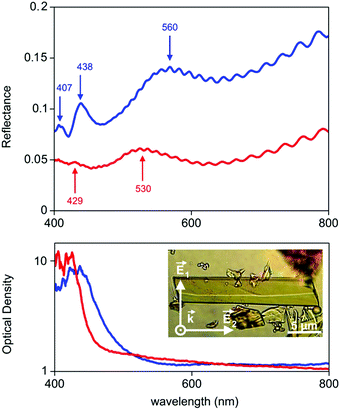
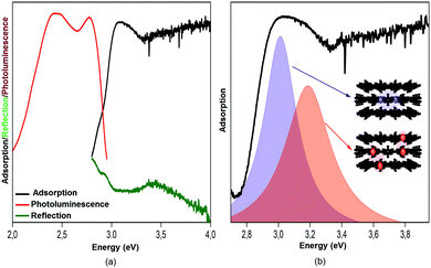
The last 15 years have been characterized by a great boom in the production and study of metal–organic frameworks and coordination polymers. These materials have proved to be excellent sorbents for gases, objects for storing hydrogen (as fuel), catalysts, elements of analytical devices for separating substances, as well as demonstrating unique physical properties in the field of ferroelectricity, non-linear optics, and magnetism. However, in addition to the existing broad scope of applications mainly due to a huge surface area, recently also unique features such as strong optical anisotropy in the visible region have been studied,32 which were detected via reflection/absorption spectra (Fig. 8), depending on the direction of the polarization vector.These properties hold great promise for use in the management of single crystals of MOFs in controlling photoexcitation under the influence of light, like non-linear and quantum metamaterials. For example, a highly stable metal–organic framework based on trinuclear iron(III) secondary building units (SBUs) linked by tetracarboxylic linkers with an anthracene core32 may have unique metamaterial properties by ordering metal atoms (Fe chains) and dielectric elements in one crystal.
In general, MOFs are semiconducting or dielectric microcrystals whose nodes contain metal ions or polyvalent metal clusters connected by organic ligands (linkers). These may comprise both donor and acceptor groups, as well as forming primary structure elements which give rise to the manifestation of various physical properties. By combining the components and varying the synthesis parameters, one can produce a huge variety of structures for MOFs, thereby affecting the desired properties of the material. The size and shape of pores of the formed framework are determined by the length and functionality of the organic component.33 Thus, by varying the initial molecular units, one can obtain final products with different architectures. One example is the use of heterocyclic molecules and molecules with hydrocarbon tails which allow for rotation around its axis, making it difficult to control the metal ion–ligand environment. In this case, preference is given to rigid aromatic carboxylate ligands, which possess high chelating ability, allowing metal ions to be fixed in the nodes of the produced lattice.34
From a technical point of view, the major drawbacks of the existing methods for the preparation of MOFs are as follows: high energy costs, insufficient size of produced single crystals for studying their structural characteristics, low yield of the expected product, and labor-intensive methods for the synthesis and purification of the product. Equally important is instability in moist air and fragility, which severely limits the possibilities of practical applications. However, for the application of MOF crystals in metamaterials the main drawback is the lack of knowledge and methods for obtaining the order of structures in the area of more than 5 nm. The first priority questions arising from numerous studies are what parameters explicitly influence the produced framework architecture, how they can be corrected, and what relationships exist between the architecture and physical characteristics. In an attempt to determine the assumed relationships, a comparison of methods for the preparation of metal–organic frameworks with the organization of structures obtained during synthesis, as well as attempts to establish ways of developing non-linear optical properties of MOF crystals, is given below.
2.1 Measurements of non-linear optical properties of metal–organic frameworks
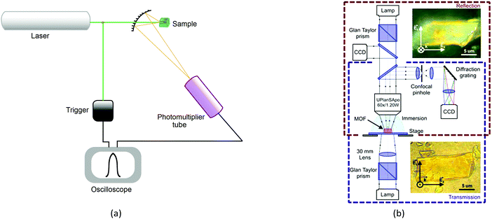
The recognized procedures to study the process of second harmonic generation are the Kurtz and Perry method (1968) for powder samples, Hauchecorne (1971) for measurements in liquids, as well as for the measurement of individual non-linearities for molecules in solution, Levine (1976), Oudar (1977), and finally, Jerphagnon and Kurtz (1970), who improved the procedure for the investigation of processes occurring in crystals, known as the Maker-fringe methods. Thus, successfully tested techniques for studying molecular, polycrystalline and single-crystal samples are universal for measuring response of various materials. The Kurtz and Perry method is the most frequently used for studying MOFs, despite the fact that powder analysis does not allow directed excitations along the crystal planes and thereby limits the analysis of properties in the area of metamaterials.The method entails placing the sample in the form of a powder (about 50 mg) into a cell and irradiation with a low-energy laser (Fig. 9a). The intensity of second harmonic generation is measured using a photomultiplier. Results are usually compared with α-quartz.
2.2 The relationship between the SHG and the size of the crystal
There is evidence that the SHG intensity depends on the crystal size. For materials such as LiNbO3, where type 1 phase-matching, or index matching, occurs when the phase velocity of the fundamental radiation (1064 nm) equals the second harmonic (532 nm), the SHG intensity increases with the particle size and eventually reaches a plateau. In materials with no phase-matching (such as quartz), the intensity efficiency will reach a maximum value and then decrease, as the particle size increases. Therefore, the SHG measurement as a function of particle size is necessary for more accurate and reliable results.35The efficiency of generation of second harmonic and other high-order non-linearities (piezo effect, wave mixing, etc.) becomes essential with an increase in crystallinity of the sample. It is due to the fact that generation is directly related to the type of crystal and its spatial orientation. This necessitates working in three dimensions with single crystals rather than powders and multicrystalline samples. We have, therefore, implemented the concept of optical studies of single crystals of MOFs (Fig. 9b). The concept is pretty simple, but very useful: a confocal system for detecting the optical signals (luminescence, reflection, second harmonic and others) is associated with two optical channels (or three, for luminescence). The optical channels can independently move in space due to the mechanical and optical elements in each channel; the single crystal is on a piezo stage which allows to locally excite it at any point and angle and collects the signals from anywhere. The excitation area is limited by diffraction but the collection area can be much smaller due to a confocal pinhole. The combination of different optical elements (Glan–Taylor prisms, quarter-wave plate, immersion objectives, etc.) in the channels allows to perform all optical experiments with the single crystal consecutively or two experiments simultaneously (e.g., luminescence and transmission). This system is well described32 and allows studying non-linear optical effects (exciton luminescence or birefringence) in different points of single microcrystals.
3. Metal–organic frameworks for non-linear optics
3.1 Producing metal–organic frameworks for non-linear optics
The question as to what method can successfully combine the possibilities of producing the desired crystal structure (inorganic component) and a variety of synthetic possibilities of the organic component has been posed by researchers for several years.The main way to obtain the desired structure in the synthesis of metal–organic frameworks is the so-called strategy of secondary building units (SBUs).75 This strategy is based on molecular or ionic assemblies and leads to the formation of secondary structural units. Non-centrosymmetric organization is a prerequisite for the generation of non-linear optical properties of bulk materials. For conventional methods of producing metal–organic frameworks, the creation of such non-centrosymmetric structures is challenging. The most successful SBUs may include metals connected with chiral ligands, since such materials were successfully used in selective catalysis and stereoselective separation.76 Not only can the coordination of the organic ligand to a metal ion yield an increase in charge transfer transitions, but it also allows organic chromophores to assemble in highly ordered geometries like octahedra and tetrahedra, which is infrequently observed for organic materials. This interaction produces charge transfer in several directions. In addition, this is the type of structure that is relatively easy to obtain by selecting the right combination of metal ions and organic ligands. Table 1 summarizes various metal–organic frameworks and coordination polymers obtained by different approaches and their efficiency in second harmonic generation.
| Entry | Composition | Ligand | Space group | SHG | Ref. |
|---|---|---|---|---|---|
| 1 | [Zn2(X)(EtOH)·3H2O]n | X = tetrakis[4-(carboxyphenyl)oxamethyl]methane acid | Cc | 2.5 × KDP | 36 |
| 2 | [Cd(L-N3)2(H2O)2]n | L = trans-2,3-dihydro-2-(4′-pyridyl)-3-(3′′-tetrazolyl-phenyl)benzo[e]indole | Aba2 | 80 × urea | 37 |
| 3 | {(NH2Me2)6[Cd5(bta)4]}n | Hbta = biphenyl-2,2′,6,6′-tetracarboxylic acid | C2/c | 0.8 × KDP | 38 |
| 4 | [Cd(bphy)(SA)]n | bphy = 1,2-bis(4-pyridyl)hydrazine, H2SA = succinic acid | I213 | 0.1 × KDP | 39 |
| 5 | [Zn(cpt)(atz)]n | Hatz = 5-amino-1H-tetrazol, Hcpt = 4-(4H-1,2,4-triazol-4-yl)benzoic acid | P212121 | 0.13 × KDP | 40 |
| 6 | [Bi2O2(pydc)]n | pydc = pyridine-2,5-dicarboxylate | P21 | 80 × SiO2 | 41 |
| 7 | [Mg2(btc)(CH3COO)(C4H9NO)3]n | H3btc = 1,3,5-benzenetricarboxylic acid | P212121 | 5 × KDP | 42 |
| 8 | {[K3Co2(LC4)3(EtOH)6]Cl}n | H2LC4 = 25,27-bis(hydroxycarbonylmethoxy)-26,28-dimethoxy-p-tert-butylcalix[4]arene | I213 | ∼0.8 × urea | 43 |
| 9 | {[Rb3Co2(LC4)3(EtOH)6]Cl}n | H2LC4 = 25,27-bis(hydroxycarbonylmethoxy)-26,28-dimethoxy-p-tert-butylcalix[4]arene | I213 | ∼1.0 × urea | 43 |
| 10 | {[N(C3H7)4]3[Ga3(btc)4]}n | H3btc = 1,3,5-benzene tricarboxylic acid | R3c | 15 × SiO2 | 44 |
| 11 | [Cd(anp)2Br2·H2O]n | anp = 2-amino-5-nitropyridine | Pnn2 | 2.1 × KDP | 45 |
| 12 | {[Ce(L-tart)(CH2OHCH2OH)(H2O)]Cl}n | L-H2tart = L-tartaric acid | P21 | 0.5 × urea | 46 |
| 13 | {[Ce(D-tart)(CH2OHCH2OH)(H2O)]Cl}n | D-H2tart = D-tartaric acid | P21 | 0.5 × urea | 46 |
| 14 | [Co(L)(bimb)·EtOH·H2O]n | L = (R)-4-(4-(1-carboxyethoxy)phenoxy)-3-fluorobenzoic acid, bimb = 4,4-bis(1H-imidazol-1-yl-methyl)biphenyl | P212121 | 0.3 × urea | 47 |
| 15 | [Co(L)(bimb)·EtOH·H2O]n | L = (R)-4-(4-(1-carboxyethoxy)phenoxy)-3-chlorobenzoic acid, bimb = 4,4-bis(1H-imidazol-1-yl-methyl)biphenyl | P212121 | 0.3 × urea | 47 |
| 16 | [Co(L)(bimb)·EtOH·H2O]n | L = (R)-4-(4-(1-carboxyethoxy) phenoxy)-3-nitroaniline acid, bimb = 4,4-bis(1H-imidazol-1-yl-methyl)biphenyl | P212121 | 0.3 × urea | 47 |
| 17 | [Ni2(H2O)(L)2(bpp)2·H2O]n | H2L = 4,4′-(phenylazanediyl)dibenzoic acid, bpp = 1,3-di(pyridin-4-yl)propane | P21 | 0.7 × urea | 48 |
| 18 | [Cs(L)·H2O]n | HL = L-malic acid | P21 | 4.24 × KDP | 49 |
| 19 | [Zn2(L)3(NO3)2·2NO3·2CH3CN]n | L = (1R,2R)-1,2-bis(4-(1,2,4-triazolyl))cyclohexane | P41212 | 0.9 × KDP | 50 |
| 20 | [AgL·OH·2H2O]n | L = (1R,2R)-1,2-bis(4-(1,2,4-triazolyl))cyclohexane | P3121 | 0.1 × KDP | 50 |
| 21 | [Zn(tzb)]n | H2tzb = 1H-tetrazolate-5-butyric acid | Pca21 | 0.5 × KDP | 51 |
| 22 | [Zn(dba)(Hpyim)·H2O]n | H2dba = 4,4′-methylenedibenzoic acid, Hpyim = 2-(2-pyridyl)imidazole | Cc | 0.8 × urea | 52 |
| 23 | [Sr(Hsip)(H2O)3·H2O]n | H3sip = 5-sulfoisophthalic acid | Ama2 | 4 × KDP | 53 |
| 24 | [Zn(dcmp)2]n | H2dcmp = 2,5-dicarboxy-1-methylpyridinium chloride | Fdd2 | 7 × KDP | 54 |
| 25 | [Zn(ima)2]n | ima = 2-(1H-imidazole-1-yl)acetate | Cc | 0.5 × urea | 55 |
| 26 | {[Cu(PPh3)(L)](ClO4)}n | L = N,N-(2-pyridyl)(4-pyridylmethyl)amine | Cc | 1.5 × urea | 56 |
| 27 | [Mn(Hpidc)(H2O)·2H2O]n | H3pidc = 2-(pyridin-4-yl)-1H-imidazole-4,5-dicarboxylic acid | Pna21 | 1.5 × KDP | 57 |
| 28 | [Ag2(Hpidc)]n | H3pidc = 2-(pyridin-4-yl)-1H-imidazole-4,5-dicarboxylaic acid | Cc | 0.9 × urea | 58 |
| 29 | [Cd((S)-ptz)2]n | (S)-Hptz = 5-[(2S)-pyrrolidine-2-yl]-1H-tetrazole | P21 | 0.35 × KDP | 59 |
| 30 | [Zn((S)-ptz)2]n | (S)-Hptz = 5-[(2S)-pyrrolidine-2-yl]-1H-tetrazole | P21 | 0.40 × KDP | 59 |
| 31 | [Zn2(L)2(4,4′-bipy)2]n | H2L = (S)-(−)-1,10-binaphtho-2,2′-diacetic acid, 4,4′-bipy = 4,4′-bipyridine | P1 | 0.17 × KDP | 60 |
| 32 | [Zn(L)(biim-4)·H2O]n | H2L = (S)-(−)-1,10-binaphtho-2,2′-diacetic acid, biim-4 = 1,1′-(1,4-butanediyl)bis(imidazole) | P43 | 0.08 × KDP | 60 |
| 33 | [Zn3(L)3(btb)(H2O)2]n | H2L = (S)-(−)-1,10-binaphtho-2,2′-diacetic acid, btb = 1,6-bis(1,2,4-triazol-1-yl)hexane | P21 | 0.10 × KDP | 60 |
| 34 | [Cu(1,3-bdc)(opy)]n | 1,3-H2bdc = isophthalic acid, opy = 4,4′-(oxybis(4,1-phenylene))dipyridine | P65 | 0.3 × urea | 61 |
| 35 | [LuCl3(H2L)(MeOH)·H2O]n | H2L = N,N′-bis(salicylidene)-1,2-cyclohexanediamine | Pna21 | 0.4 × urea | 62 |
| 36 | [Mg(L)(DMF)(H2O)3]n | H2L = 4,4′-(9,9-dimethyl-9H-fluorene-2,7-diyl)dibenzoic acid | P21 | 0.4 × urea | 63 |
| 37 | [Zn(L)(DMF)]n | H2L = 4,4′-(9,9-dimethyl-9H-fluorene-2,7-diyl)dibenzoic acid | Aba2 | 0.8 × urea | 63 |
| 38 | [Cd2L(H2O)2·solvent]n | H4L = tetrakis[4-(carboxyphenyl)oxamethyl]methane acid, solvent = DMA/H2O | Fdd2 | 3.6 × KDP | 64 |
| 39 | Zn(bipa)(py)2H2O | H2bipa = 5-bromoisophthalic acid, py = pyridine | P212121 | 0.7 × urea | 65 |
| 40 | [Zn2Cl(btc)(titmb)]n | titmb = 1,3,5-tris(1-imidazol-1-ylmethyl)-2,4,6-trimethylbenzene, H3btc = 1,3,5-benzene-tricarboxylic acid | P212121 | 0.7 × urea | 66 |
| 41 | [Zn3(btc)2(titmb)·H2O]n | titmb = 1,3,5-tris(1-imidazol-1-ylmethyl)-2,4,6-trimethylbenzene, H3btc = 1,3,5-benzene-tricarboxylic acid | P21 | 0.8 × urea | 66 |
| 42 | [Zn(paba)2·H2O]n | Hpaba = p-aminobenzoic acid | P212121 | 1 × KDP | 67 |
| 43 | [Zn(tzf)2]n | Htzf = 1H-tetrazole-5-formic acid |
I![[4 with combining macron]](https://www.rsc.org/images/entities/char_0034_0304.gif) 2d 2d |
1.1 × KDP | 68 |
| 44 | [NaZn(acac)2(AcO)·EtOH]n | acac = acetylacetonate | P212121 | 15 × KDP | 69 |
| 45 | [Cd2(4,4′-bipy)2(H2O)3(SO4)2·3H2O]n | 4,4′-bipy = 4,4′-bipyridine | C2 | 0.27 × KDP | 70 |
| 46 | [Ag4(dob)4(BF4)4]n | dob = 1,3-di(2-oxazolinyl)benzene | Cc | 0.3 × urea | 71 |
| 47 | [Zn(L)2]n | HL = 1,3-dithiole-2-tetrazole |
I![[4 with combining macron]](https://www.rsc.org/images/entities/char_0034_0304.gif) 2d 2d |
0.7 × KDP | 72 |
| 48 | {[Ca(L)(H2O)2]Cl2}n | L = β-D-fructose | P21 | 0.466 × KDP | 73 |
| 49 | {[Ca(L)2(H2O)2]Cl2·H2O}n | L = β-D-fructose | C2 | 0.122 × KDP | 73 |
| 50 | [Zn2(1,3-bdc)(ppa)2·(H2O)]n | ppa = pipemidic acid, H2bdc = 1,3-benzenedicarboxylic acid | Cc | 5.6 × KDP | 74 |
3.2 Ligands
Deprotonated 2-hydroxy-nicotinic acid is capable of coordinating a metal using different functional groups, yielding four- and six-membered chelate rings (Fig. 10). The resulting compound {[Zn2(nica)2(bpy)1.5(H2O)]·0.5(bpy)·3H2O}n was obtained by hydrothermal synthesis and investigated by IR spectroscopy to determine possible coordination modes of the ligand with the metal ion. As a result, eight different coordination modes were suggested.
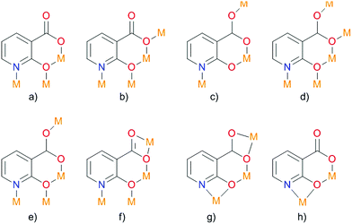 | ||
| Fig. 10 Possible coordination modes of deprotonated 2-hydroxy-nicotinic acid. Adapted from ref. 77 with permission from © 1996–2016 MDPI AG. | ||
Single-crystal diffraction studies have shown that the resulting compound crystallized in the crystal class mm2 (point group C2v),77 in the orthorhombic non-centrosymmetric space group Fdd2. The N,O- and O,O-chelation of the ZnII ions by nica2− results in the formation of zig-zag channels along the c-axis. The modest SHG response in the present case can be attributed partly to the partial cancellation of non-centrosymmetry between the intercrossing zig-zag chains as the dipole moments are cancelled out and partly to the absorption by the crystal in the presence of bpy guest molecules. Strong hydrogen interaction of the water molecules with the carboxyl group in nica2− occurs. Also, a strong CH⋯π interaction (purple and blue dashed lines) and a relatively weak π–π interaction (green dashed line) are observed between the coordinated and guest bpy ligands. In the resulting non-centrosymmetric product, which crystallizes in the space group Fdd2, the polar axis lies along the zig-zag chain (Fig. 11). Polarity arises due to the location of the bridging nica2− ligands.
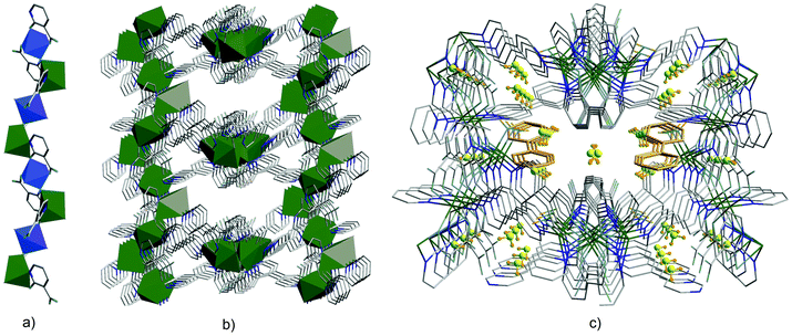 | ||
| Fig. 11 (a) Formation of metal chains in {[Zn2(nica)2(bpy)1.5(H2O)]·0.5(bpy)·3H2O}n through coordination of nica2− (H2nica = nicotinic acid) ligands in a chelating manner; (b) the 3D framework in {[Zn2(nica)2(bpy)1.5(H2O)]·0.5(bpy)·3H2O}n viewed along the c-axis; (c) incorporation of guest molecules such as water and 4,4′-bipyridine. Adapted from ref. 77 with permission from © 1996–2016 MDPI AG. | ||
For this type of structure, non-linear optical properties were investigated in accordance with the methods proposed by Kurtz and Perry. The second harmonic generation intensity measured in a single crystal using a laser source is lower than that in SiO2, and the corresponding peak is observed at 532 nm. The efficiency of second harmonic generation depends on several factors, such as non-centrosymmetricity, intensity of push–pull dipole effects caused by ligands, donor–acceptor bonds in the framework, interaction between the guest molecules embedded in the structure and the functional groups of the ligands.78 A small second harmonic response in this case can be explained by the partial absorption of the crystal due to the presence of guest bpy molecules, as well as by a decrease in non-centrosymmetricity upon crossing the zig-zag chain because the dipole moments of the functional units are greatly reduced.
Another example is 2-(pyridin-4-yl)-1H-imidazole-4,5-dicarboxylic acid (H3pidc). In [Zn2(pidc)(H2O)Cl]n the asymmetric unit consists of two independent zinc ions, one completely deprotonated ligand, one coordinated water molecule and one coordinated Cl− ion (Fig. 12).78 The structure of the material in general is a two-dimensional grid, while hydrogen bonds allow the dimensionality of the system to be increased to 3D. A different coordination mode is observed in [Mn(Hpidc)(H2O)·2H2O]n, in which three metal centers are chelated in an O,O- and N,O-bonding mode as well as a monodentate coordination of a pyridyl group (Fig. 13), eventually resulting in a three-dimensional network. Moreover, the considered structure also forms channels in the [001] direction filled with non-coordinating water molecules connected via hydrogen bonds. Various coordination modes allow the pyridine ring and imidazole to take up different positions. The fact that the carboxyl group and the imidazole ring cannot be located in the same plane ultimately leads to the formation of a non-centrosymmetric structure.78,79 Coordination of the ligand increases its rigidity, resulting in a donor–acceptor system, which is necessary for the manifestation of a non-linear optical effect. The SHG measurement results showed that the magnitude of response in the first case was comparable with urea, while in the second case the value was about 0.8 relative to urea.78 With regard to symmetry, [Zn2(pidc)(H2O)Cl]n belongs to the class 222 and point group symmetry D2, while complex [Mn(Hpidc)(H2O)·2H2O]n crystallizes in the space group Cc, which belongs to a polar point group Cs.
 | ||
| Fig. 12 Section of the structure of [Zn2(pidc)(H2O)Cl]n.78 | ||
 | ||
| Fig. 13 Section of the structure of [Mn(Hpidc)(H2O)·2H2O]n.78 | ||
Different structures were observed for compounds with p-pyridine carboxylato or m-pyridine carboxylato ligands (Fig. 14).80 Although the difference is small, m-pyridine carboxylate led to the formation of 2D structures, in contrast to p-pyridine carboxylate, which gave 3D structures. This type of 2D structure is formed when a metal center is coordinated by unsymmetric bifunctional ligands.80 If conditions are favorable, the 2D grids may form a non-centrosymmetric crystal.80 In addition, m-pyridine carboxylates have their own electronic asymmetry, which also has a positive effect on the NLO properties.
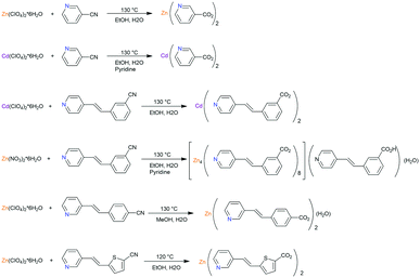 | ||
| Fig. 14 Synthesis of 2D coordination polymers consisting of d10 metals and bridging p-pyridine carboxylato ligands. Adopted from ref. 80. | ||
Crystals of [Cu(H2Me4BPZ)Br·0.5H2O]n (H2Me4BPZ = 3,3′,5,5′-tetramethyl-4,4′-bipyrazole), obtained by the reaction of CuBr and H2Me4BPZ under solvothermal conditions, not only demonstrate a SHG value comparable to that of KDP,81 but also exhibit ferroelectric properties. In this species, a 3D porous structure is formed by connecting four adjacent binding ligands of H2Me4BPZ (Fig. 15), which in turn are connected by serrated channels of [CuBr].81
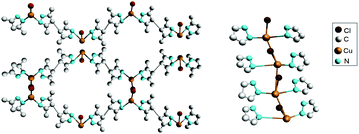 | ||
| Fig. 15 Part of the crystalline structure of [Cu(H2Me4BPZ)Br·0.5H2O]n. Left: 1D serrated channels extending along the c-axis; right: side view of the 3D framework. Adapted from ref. 81. Copyright © 2016 Elsevier B.V. | ||
It is, however, important that the used compounds are stable under the influence of laser radiation, in contrast to, for example, coordination polymers,82 so that studying the second harmonic generation is technically possible. For example, measurements of the second harmonic generation effect failed for the non-centrosymmetric thallium(I) coordination polymer [Tl4(adc)(ox)]n (adc = acetylenedicarboxylate, ox = oxalate) (Fig. 16) since decomposition by the laser beam occurred, releasing potentially toxic thallium(I) compounds.82
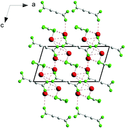 | ||
| Fig. 16 Schematic diagram for [Tl4(adc)(ox)]n in the [010] projection. Adapted from ref. 82. Copyright © 2016 Elsevier. | ||
Previously, an attempt was made to study how the introduction of another metal in the metal–organic framework structure will affect the non-linear optical properties of the system. The first work on heterometallic compounds was focused on Cd2+ and Li+ ions. It was shown that the addition of alkali and alkaline earth metals to the framework could significantly enhance the SHG.83 The first frameworks were synthesized in the presence of LiNO3 or NH4NO3 under solvothermal conditions.83 Substituted 1,3- or 1,4-benzenedicarboxylate were employed in the synthesis of heterometallic compounds, {(NH2Me2)[CdLi(p-bdc)2]·3CH3OH}n (1), {(NH2Me2)2[{Cd(p-bdc)2}3(NHMe2)]}n (2), {(NH2Me2)[CdLi(m-bdc)2]}n (3), {(NH2Me2)[{Cd(OH-m-Hbdc)(OH-m-bdc)}3(DMF)3(CH3OH)·3H2O]}n (4), [Cd1.5Li(5-tBu-m-bdc)2(DMF)2]n (5), {(NH2Me2)[CdLi(oba)2]}n (6), {(NH2Me2)[CdLi(sdba)2·3DMF3·CH3OH]}n (7), and {(NH2Me2)[Cd3(H2O)3(OH)(sdba)3]}n (8) (p-H2bdc = 1,4-benzenedicarboxylic acid, m-H2bdc = 1,3-benzenedicarboxylic acid, OH-m-H2bdc = 5-hydroxy-1,3-benzenedicarboxylic acid, 5-tBu-m-H2bdc = tert-butyl-1,3-benzenedicarboxylic acid, H2oba = 4,4′-oxybis(benzoic acid) and H2sdba = 4,4′-sulfonyldibenzoic acid), using the solvothermal method.83 Six compounds (2, 3, 4, 6, 7, and 8) were also investigated qualitatively based on the fact that they all crystallize in acentric (3) or chiral space groups (2, 4, 6, 7, and 8). Compound 2 exhibited the lowest SHG value, which is nonetheless still about two times greater than quartz, due to the fact that the shortest ligand with a lower degree of conjugation was used. Compound 6 exhibited the highest value, namely 800 times greater than quartz, and has good prospects, since its characteristics are better than that of technologically important LiNbO3 (600 times greater SHG than that of quartz). The exceptions to the series are 1 and 5, since they crystallize in centrosymmetric structures.
However, the use of the proposed strategy83 was not successful in other cases; for example, [CdCa(m-bdc)2(DMF)2]n, [CdCa(OH-m-bdc)2(H2O)2·2NHMe2]n, and [CdSr2(μ-bdc)2(NO3)2(DMF)4]n show weak SHG values, despite crystallizing in non-centrosymmetric structures.84
A metal–organic framework based on a trinickel secondary building unit was produced using a ligand with two chiral centers, which simultaneously serve as the donor and the acceptor in the system (Fig. 17). Such properties of a ligand are necessary for the generation of non-linear optical properties. The cyano group can be converted to a tetrazole in a click reaction with NaN3. The molecule with two chiral centers (Fig. 17a), which has no symmetry, also crystallizes in a non-centrosymmetric space group. The significant enhancement of second harmonic generation was related to the cumulative effect caused by a high degree of asymmetry of the ligand due to the so-called pull–push effect and the metal–ligand coordination.86
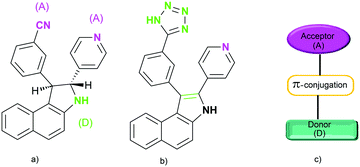 | ||
| Fig. 17 (a) Ligand reported by Xiong et al.; (b) the corresponding in situ generated ligand; and (c) schematic illustration of a donor–acceptor system. Adapted from ref. 86 (Copyright © 2005, American Chemical Society). | ||
Coordination polymers [Zn(bindc)Cl2]n, [Zn(bindc)Br2]n and [Ag(bindc)NO3]n (bindc = N,N′-bis(isonicotinoyl)-(1R,2R)-diaminocyclohexane) forming a helical superstructure, which is known to result in considerable enhancement of second harmonic generation, were constructed from the C2-symmetrical chiral N,N′-bis(isonicotinoyl)-(1R,2R)-diaminocyclohexane (bindc) and ZnII, AgI and CuIvia complementary hydrogen interactions of the bis(amido) ligands.87 To ensure the formation of a highly dimensional structure, ligands containing amide groups were selected, because these groups provide strong hydrogen interactions with predictable regularity, which is particularly useful for self-assembly processes.87
Measurements using the Kurtz–Perry method yielded values of 0.8 U (1 U = SHG of urea) for bindc, even though this molecule does not have strong pull–push effects. This is due to the helical superstructure in bindc. This is not observed in coordination polymers or MOFs, where the pyridyl nitrogen atom is involved in the coordination to metal ions.87
The zinc complex [Zn(bindc)Cl2]n has a tetrahedral coordination, including two chloro ligands and two nitrogen atoms of two different bindc molecules. Coordinated dipyridyl of the ligand molecules forms an extended one-dimensional channel along the b-axis, complementary amide hydrogen bonds form one-dimensional zig-zag chains “parallel” to one another along the crystallographic c-axis, and the chloro ligands approach the pyridyl hydrogen atoms along the a-axis, resulting in a three-dimensional network. The replacement of zinc(II) with other metal(II) ions does not lead to significant changes in the second harmonic generation, but affects the thermal stability of the material.87
It follows from the above that non-centrosymmetric MOFs, which can be obtained by employing aromatic chiral ligands or asymmetric ligands with a pull–push effect (with an electron donor–acceptor system), can replace the existing materials for NLO, but the synthetic methods are complicated and chiral ligands can be expensive. An alternative synthetic strategy is so-called spontaneous resolution based on achiral ligands. Spontaneous resolution is the separation of racemates into their enantiomers in the form of conglomerates, which is a rare phenomenon. To obtain a non-centrosymmetric or chiral porous material by spontaneous resolution, it is preferable to use rigid achiral ligands with low symmetry. For example, deprotonated pyridine-3,5-dicarboxylic acid (3,5-H2PDC) was employed as a rigid V-shaped tridentate ligand with a lower symmetry (C2v) compared to typical tridentate ligands of deprotonated 1,3,5-benezetricarboxylic acid (D3d symmetry).88 One advantage of dianionic 3,5-PDC in the coordination of a divalent metal is the formation of neutral compounds.88
It was shown that the solvent plays a key role in the preparation of metal–organic frameworks influencing the final structure. Using spontaneous resolution under solvothermal conditions and solvents such as DMF and ethylene glycol, a chiral MOF, [Mn(3,5-PDC)(H2O)(glycol)]n with helical channels (Fig. 18), and two isostructural non-centrosymmetric MOFs, [M(3,5-PDC)(H2O)(glycol)·H2O]n (M = Co, Ni), were synthesized. Unfortunately, measuring second harmonic generation was outside the scope of this study.88 However, this work demonstrates a new synthetic route for so-called spontaneous resolution, which turned out to be perfectly suited for the preparation of chiral and non-centrosymmetric MOFs.
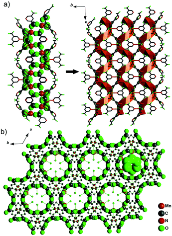 | ||
| Fig. 18 (a) The Mn–O–C chain along the 61 axis connected to each other to form the chiral JUC-58 framework and (b) the network of JUC-58 looking down the 61 axis (001 direction), showing the homochiral water chain included in the channels. Adapted from ref. 88 (Copyright © 2013 Elsevier). | ||
It was also shown that even weak interactions between guest molecules and the framework can cause a transition from a chiral to an achiral structure depending on the size of the guest species. One example is Zn(ain)2 (Hain = 2-aminoisonicotinic acid) in which a transition from a chiral to an achiral crystal was observed depending on the solvent used in the synthesis (DMA or DMF). The compounds [Zn(ain)2·(DMA)]n and [Zn(ain)2·(DMF)]n have the same structural network, but slightly different crystal symmetries, and their channels have a different shape,89 due to the different sizes of DMA and DMF.89 Such seemingly small differences can lead to a probable variation of the second harmonic values. It is interesting to note that simply immersing the obtained product in another solvent does not result in structural changes.89
Another interesting case is a series of pillared-layer metal–organic frameworks [Cd(5-aip)(bpy)·1.5DMA]n, [Cu(5-aip)(bpy)·1.3DMA]n, [Co(5-aip)(bpy)·1.6DMA]n, and [Cd(5-aip)(bpy)·0.5(H2O)·1.3DMA]n derived from 5-aminoisophthalic acid (Haip), 4,4′-bipyridine (bpy) and MII. A symmetry change from chiral to achiral occurs by soaking the crystals in methanol at room temperature. This fact is explained by a change in the torsion angle of the aromatic rings of the bipyridine ligands after substitution of DMA molecules in the channels with methanol.90
Strategies for potentially adjusting the symmetry of crystals have been reported.91 However, one should always consider the solvent effect to control changes in lattice parameters with a change in crystal symmetry, which may affect the mechanical properties of the material. Also, substitution conditions must be chosen which ensure that the process proceeds to completion.
Also, apart from using asymmetric ligands, there is a strategy of using racemates. One example is diamond-like [Cd(Imazethapyr)2]n which crystallizes in a non-centrosymmetric space group (Fdd2) belonging to a polar point group (C2v). This metal–organic framework is obtained by the reaction of racemic H-Imazethapyr with Cd(ClO4)2·6H2O under hydrothermal conditions (Fig. 19).92 There are no network interpenetrations in the final structure due to steric constraints and short distances between two adjacent cadmium ions. The second harmonic generation value for Cd(Imazethapyr)2 is 20 times higher than that of potassium dihydrogen phosphate.
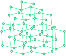 | ||
| Fig. 19 A simplified 3D diamond-like structure of Cd(Imazethapyr)2. Straight lines resemble ligands, balls correspond to metal ions. Adapted from ref. 92 (Copyright © 2002, American Chemical Society). | ||
3.3 Diamondoid structures
The most likely candidates for producing crystals with non-linear optical properties are metal ions, which have a coordination number of 4 or 8 and are connected via a bifunctional ligand. Such components tend to form the so-called diamond structure (Fig. 20).89,91,93 According to several studies, diamondoid structures are defined as promising in terms of obtaining non-centrosymmetric structures. Crystals of diamond-type inherently crystallize in a centrosymmetric space group (Fd3m), so that the inversion center is in the middle of the C–C bond between two adjacent nodes. To obtain non-centrosymmetric structures, non-centrosymmetric bridging ligands and different adjacent connecting nodes (Fig. 21) can be used.80 Assuming a diamondoid topology with an Si–O–Si bond angle of 144°, one can produce V-shaped bonds between two adjacent Si atoms, which generally results in non-centrosymmetric structures (Fig. 22).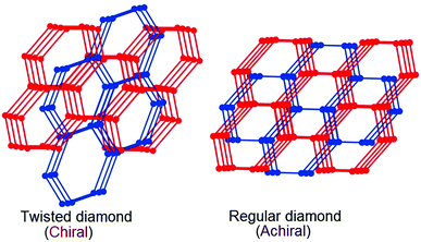 | ||
| Fig. 20 Topological view of the structural transformation from the chiral dia net to the achiral dia net. Adapted from ref. 89 (© Royal Society of Chemistry 2016). | ||
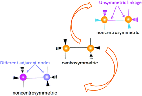 | ||
| Fig. 21 Two methods for removing an inversion center in a diamondoid structure: (top) using unsymmetrical linkage and (below) using different adjacent nodes. Adapted from ref. 80 (Copyright © 2012, American Chemical Society). | ||
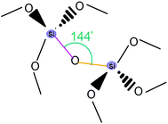 | ||
| Fig. 22 An illustrative example for α-quartz. Adapted from ref. 80 (Copyright © 2012, American Chemical Society). | ||
The diamondoid structure can be adjusted by changing the length of the ligand in the system. Thus, changing the length of the p-pyridine carboxylato ligand in Zn2+- or Cd2+-based two-dimensional coordination polymers resulted in non-centrosymmetric diamondoid structures which showed a higher SHG with a systematic increase in the length of the ligand,93–95i.e. with increasing conjugation between the donor and the acceptor, which in turn increases hyperpolarizability of the chromophores. Here, it is shown for the first time that non-linear optical properties can be changed by changing the length of the bridging conjugated ligands. For example, the obtained materials exhibit an SHG intensity of up to 400 times that of α-quartz.92
Tetrazoles can act as bridging ligands for d10 metal ions96–98 yielding a tetrahedral coordination, which enables a diamondoid structure to form 1H-tetrazolate-5-butyrate coordination polymers, [Zn(tzb)]n and [Zn(3-ptz)2]n (H2tzb = 1H-tetrazolate-5-butyric acid, 3-ptz = 5-(3-pyridyl)tetrazolate). There are no interpenetrations in the network of the resulting compound, [Zn(3-ptz)2]n, which was obtained by hydrothermal synthesis, due to the short distance between the metal ions and large substituents on the tetrazole.
3.4 Zero-dimensional objects
As was shown in several studies,99,100 cations with octahedral coordination, distorted by second-order Jahn–Teller effects, such as high-spin d4 (e.g., CrF2), low-spin d7 (e.g., NaNiO2), and d9 (e.g., Cu2+), are quite an important factor for non-centrosymmetricity of the structure. In the case of octahedral d9 configuration, the unpaired electron may occupy either the dz2 or dx2−y2 orbital of the eg set. If it occupies the dz2 orbital, most of the electron density will be concentrated between the metal and the two ligands on the z-axis. Thus, there will be greater electrostatic repulsion associated with these ligands than with the other four in the xy plane. This asymmetric distribution of the electron density may increase the overall energy of the system. Accordingly, elongation of bonds along the z-axis occurs, resulting in a lower symmetry.101–109 Unfortunately, such an approach cannot warrant the expected result; therefore, the main task is controlling the macroscopic symmetry of the system.110In the crystallization of a material, its symmetry may be affected not only by the selected cation, but also by its environment arising from the interaction of hydrogen bonds.110 To determine the influence of hydrogen bonding on the orientation of the structure, two compounds were chosen: centrosymmetric [NMe4]2[TiF6] and polar non-centrosymmetric [C(NH2)3]2[TiF6] (Fig. 23). With regards to non-linear optical properties, a value 25 times higher than that of SiO2 was obtained. The compounds under consideration have the same type of structure, the zero-dimensional TiF6 octahedra and organic cations, but they crystallize with different symmetries. In the case of [C(NH2)3]2[TiF6], the alignment of the distorted octahedra is mainly responsible for the polar crystal structure and second harmonic generation, respectively. The eccentric distortion of the TiF6 octahedra is due to the interaction of hydrogen bonds between fluoride in the [TiF6]2− octahedra and the H–N bonds of the [C(NH2)3]+ cation, which are the key factor in determining the polar structure upon aligning the TiF6 octahedra. In contrast, interactions between the hydrogen atoms in [NMe4]+ and fluoride in [TiF6]2− in [NMe4]2[TiF6] are extremely weak. The effect achieved in this case is incomparably smaller than strong hydrogen interactions present in [C(NH2)3]2[TiF6].
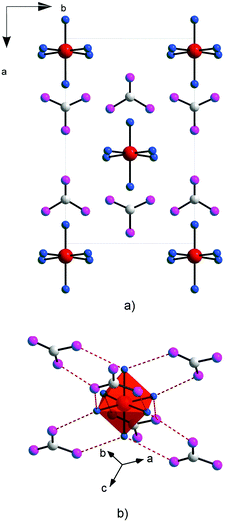 | ||
| Fig. 23 Representation of the non-centrosymmetric structure of [C(NH2)3]2[TiF6]; (a) in the ab plane; and (b) showing the F⋯H bonds. Adopted from ref. 110 (Copyright © 2011 Elsevier Inc). | ||
3.5 Octupolar MOFs
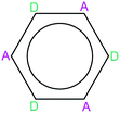
Molecules possessing octupolar symmetry have long been the focus of investigations of non-linear optical properties. While dipoles tend to centrosymmetric organization, molecules with octupolar symmetry tend to form non-centrosymmetric structures.111 It has been successfully demonstrated previously that a number of individual molecules with octupolar symmetry yield high second harmonic generation.111 An example of a system with octupolar symmetry is an octupole consisting of charges in the corners of a cube, where positive charges are located at positions (1,0,0), (0,1,0), (0,0,1) and (1,1,1), and negative charges at points (0,0,0), (1,1,0), (1,0,1) and (0,1,1).111 In organic chemistry, an example of an octupolar molecule is a benzene ring, in which electron donors and acceptors alternate (Fig. 24).111 Such a molecule has high non-linear optical properties and does not have a permanent dipole moment, avoiding probable centrosymmetric crystallization.111 Typical examples are molecules with a C3 symmetry axis, since it was shown that among the molecules with Cn symmetry axes, only molecules with a C3 axis do not have a dipole moment, but possess a finite hyperpolarizability component.111With regards to MOFs, in order to obtain non-centrosymmetric octupolar structures with non-linear optical properties, trinuclear metal clusters can be used as building units. One example is {[Cd3(μ3-OH)((E)-4-pyv-4-bza)3(py)6](ClO4)2}n ((E)-4-pyv-4-bza = 4-[2-(4-pyridyl)ethenyl]benzoate) obtained from Cd(ClO4)2·6H2O and ethyl 4-[2-(4-pyridyl)ethenyl]benzoate using the hydro/solvothermal method.112 Cadmium carboxylates, acting as secondary building blocks, give rise to a symmetry with 3-fold rotational symmetry (octupolar chromophores). The result is a chiral two-dimensional structure (Fig. 25). The measured signal of second harmonic generation has 130 times greater intensity than that of α-quartz.112
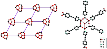 | ||
| Fig. 25 Left: Schematic representation of the cationic building block for the octupolar structure of {[Cd3(μ3-OH)((E)-4-pyv-4-bza)3(py)6](ClO4)2}n. Right: Schematic representation of the 2D octupolar structure. Adapted from ref. 112. Copyright © 1999, American Chemical Society. | ||
Another example from this area is {(NH2Me2)2[Cd3(C2O4)4]·MeOH·2H2O}n, a MOF synthesized solvothermally from CdCO3 and oxalic acid.113 This compound forms a three-dimensional porous network with a cubic acentric space group (Fig. 26). The unit in this case is two sets of equilateral triangles [Cd3(C2O4)4]2− as a structural motif whose center lies on the threefold axis of rotation forming a hexameric [Cd6(C2O4)8]4− ionic cluster.113 Their interaction leads to an octupolar, 3D anionic supercage network with a rare, crystallographically imposed Td symmetry. In such a system, there are small voids which are occupied by (NH2Me2)+ cations and solvent molecules (MeOH and H2O). The complete replacement of NH2Me2+ in {(NH2Me2)2[Cd3(C2O4)4]·MeOH·2H2O}n by NH4+, K+, or Na+ was accomplished and increases the resulting response to 155-, 110-, and 90-times that of α-quartz, respectively. It appears that a decrease in the radius of the ion, which is exchanged, results in a decrease in the second harmonic generation response.113
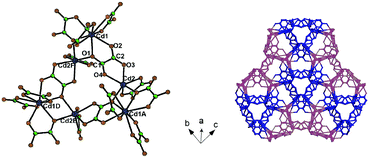 | ||
| Fig. 26 Left: Representation of the 3D anionic network of {(NH2Me2)2[Cd3(C2O4)4]·MeOH·2H2O}n; right: representation of the hexanuclear octupolar structure of [Cd6(C2O4)8]4. Adapted from ref. 113 (Copyright © 2007 John Wiley & Sons). | ||
3.6 Effect of the degree of interpenetration of grids
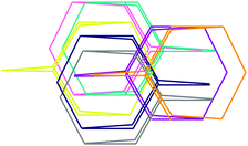
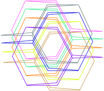
Second harmonic generation is strongly influenced by the degree of interpenetration of grids.114–117 Interpenetration can occur when large voids are formed in a diamondoid crystal by extended ligands. Examples are the structures of [Zn(4-pya)]n and [Cd(4-pya)2·H2O]n, [where 4-pya = (E)-3-(pyridin-4-yl)acrylate], which yield 5-fold interpenetration (Fig. 27) and crystallize in non-centrosymmetric space groups.114 When using a ligand such as 4-(4-pyridyl)benzoate, the degree of interpenetration can be increased up to 7 (Fig. 28) in [Cd{4-(4-pyridyl)benzoate}2·H2O]n,117 and for 4-[2-(4-pyridyl)ethenyl]benzoate, which contains an additional ethylene group, even up to 8 (Fig. 29) in [Cd(4-{2-(4-pyridyl)ethenyl}-benzoate)2]n.114 Crystallization in a chiral space group is also possible in cases when the degree of interpenetration is even, for example 10.114,115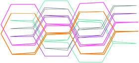 | ||
| Fig. 27 Illustration of the maximum degree of interpenetration for degree 5. Adopted from ref. 114 with permission from © 1999–2016 John Wiley & Sons, Inc. | ||
 | ||
| Fig. 28 Illustration of the maximum degree of interpenetration for degree 7. Adopted from ref. 117 with permission from © 2016 American Chemical Society. | ||
 | ||
| Fig. 29 Illustration of the maximum degree of interpenetration (for degree 8). Adopted from ref. 116 with permission from © Royal Society of Chemistry 2016. | ||
Unsymmetric ligands for achieving an unsymmetric distribution of electrons and eliminating the inversion center for MOFs with tetrahedrally coordinated metal centers (Fig. 30) were first employed in 1999.117 The degree of interpenetration may be significantly increased by increasing the length of the ligands, which promotes structures with more voluminous cavities. Since an extended ligand improves the interface between the donor and the acceptor, this in turn increases the molecular hyperpolarizability of the chromophores, which can improve the SHG of the crystal.8,11
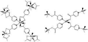 | ||
| Fig. 30 3D MOFs of diamondoid topology built from tetrahedrally coordinated Zn2+ or Cd2+ and p-pyridine carboxylate linkers. Adopted from ref. 117. Copyright © 2016 American Chemical Society. | ||
3.7 1D coordination polymers: formation of channels
Obtaining non-centrosymmetric structures with 1D channels may be interesting even despite the fact that it is virtually impossible to control the structure in the other two dimensions. The first data on a 1D coordination polymer with non-linear optical properties were reported for cadmium chalcogenocyanates.118 Anionic [Cd(XCN)3]− (X = S or Se) polymeric chains may assume a non-centrosymmetric structure with all chalcogen atoms in the trans position to the nitrogen atoms (due to the trans effect) (Fig. 31). The formation of a non-centrosymmetric structure is strongly dependent on the symmetry of the cation. A compound with a crown-ether–metal cation with a center of inversion crystallizes in a centrosymmetric space group, while the monocation [K(18-crown-6)]+, which lacks a center of inversion, leads to the formation of a non-centrosymmetric material. The observed second harmonic generation in [K(18-crown-6)][Cd(XCN)3] is 15 times higher than that of quartz.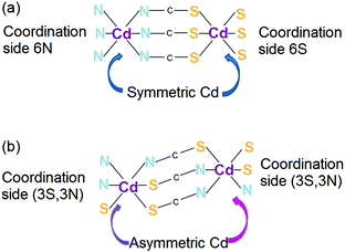 | ||
| Fig. 31 Schematic representation of (a) centrosymmetric and (b) non-centrosymmetric channels of {[Cd(SCN)3]−}n. Adapted from ref. 118. Copyright © 2016 Elsevier B.V. | ||
It is, however, also necessary to take into account the mutual orientation of the channels with respect to each other. For example, the compound [Co(pydc)(H2O)2]n·nH2O (pydc = pyridine-3,4-dicarboxylate) yields only a subtle response due to the fact that the channels are oriented antiparallel to each other, which nullifies the dipole moment, thus preventing possible second harmonic generation.119
Creating a structure with some self-blockage may be of interest as well. In [Zn(pydc)]n, three Zn2+ cations are connected by 4-[2-(4-pyridyl)ethenyl]cinnamate ligands, resulting in the formation of zig-zag channels. Parallel channels are connected by π–π interactions.120
4. New applications of MOFs in non-linear optics: prospects
4.1 Third-order NLO
A new trend is the study of non-linear optical properties of third order for MOFs, which in turn has promise for use in all-optical switching in waveguides.121 For example, crystals of [Cu3(L)2·3nH2O]n and [CuAg2(HL)2]n (H3L = chelidamic acid) have the values 1.67 × 10⁻³³ and 1.52 × 10⁻³⁰ ESU,122 which are comparable to or even greater than the traditionally used crystals.123 Thus, MOFs reveal themselves as promising materials in this field of third order non-linear effects.4.2 Control of excitons
The crystalline and organic nature of MOFs allows the existence of Coulomb-bound electron–hole pairs (excitons). The potential offered by manipulating excitons when exposed to light and electric field is the basis for modern exciton transistors and polariton lasers. Semiconductors or special two-dimensional structures were typically used in such devices. Despite the fact that extremely fast and highly efficient manipulation of excitons can be obtained for such materials, there are limitations in the operating temperatures and device architectures. Given these shortcomings, an alternative is the use of ordered organic semiconductor structures which promote a shift of the operating temperature, additionally reducing the rate of exciton recombination. With regards to the problem of a short life cycle the solution is to use layered anisotropic materials. Taking into account the facts outlined above, it can be concluded that the combination of organic nature and crystal anisotropy is an effective solution for studying exciton control at ambient temperatures.As proof-of-principle, a layered metal–organic framework [{Zn2(tbapy)(H2O)2}·3.5DEF]n (tbapy = 1,3,6,8-tetrakis(p-benzoate)pyrene) was studied by Vinogradov, Hey-Hawkins et al.124 The obtained adsorption, reflection and photoluminescence spectra indicate the presence of at least two types of excitons (Fig. 32). Since the compound has a layered structure, which limits the exciton motion in the same direction, they are divided into intra-layer, electrons and holes existing in the same layer, and inter-layer ones, located in different layers, respectively.
The study also demonstrated the efficient and independent control of excitons via disordering the structure or photoexcitation caused by light, which allows for achieving significant changes in the optical properties of single crystals. The said changes can either exist for a very short time or persist for several days. Thus, this material is promising for use in various excitonic devices.
5. Conclusions and outlook
In conclusion, in the production of NLO materials and even non-linear and quantum metamaterials, special attention should be paid to the class of metal–organic frameworks that combine the properties of organic and inorganic constituents. Particular attention should be paid to the selection of the metal–ligand pair. In order to further improve the optical properties of the produced materials, different parameters such as the length of the ligand, the degree of its substitution, the conjugation in the system, and the use of guest molecules with different natures should be adjusted. It should, however, be noted that the parameters of an obtained MOF crystal can be significantly affected by minor external influences, such as replacing solvent molecules with a different type of guest molecule, which in turn may lead to a change in the symmetry of the system. One should additionally take into account the fact that the best control in terms of prediction is provided for 3D structures, while 2D or 1D structures cannot be subjected to similar control of their architectures. It is also possible to change the degree of interpenetration of networks, which greatly affects the non-linear optical properties of the material.While many efforts are being made to design MOF architectures that exhibit the desired properties, the possibility of studying the material structure at the molecular level and the measurement of its non-linear optical characteristics without destruction of the material remains an area with fairly significant problems.
The most important goal, however, is finding a correlation between the method of production, the synthesis parameters, the properties of the starting materials, and the resulting physical and chemical characteristics. Studies in this fundamental area can bear fruit for applied use as well. If MOFs are considered as a potential replacement for existing materials for practical applications in the field of non-linear optics, then thermal stability and mechanical strength are important. It is noteworthy that MOFs, which are able to compete in SHG and at the same time have acceptable thermal stability, already exist. This demonstrates that competent elaboration of these materials could improve their competitiveness with respect to technically important ones not only in terms of the desired non-linear optical effects, but also in the relative simplicity of preparation.
The development of metal–organic frameworks may transform into a very promising area, namely, obtaining metamaterials using chemical methods. A transition from physical methods of production to chemical ones would allow simplification of the process for obtaining specific materials, as well as diversification of their final architecture. Attempts to produce metamaterials via chemical synthesis have been made, but it appears that this is not at all simple. However, more recently, it was possible to demonstrate that potential metamaterials can be obtained via chemical methods. In this respect, the development of MOFs which possess the desired properties characteristic of metamaterials via chemical methods is very promising.
List of abbreviations
| adc | Acetylenedicarboxylate |
| anp | 2-Amino-5-nitropyridine |
| BBO | Barium borate, β-BaB2O4 |
| 4,4′-bipy | 4,4′-Bipyridine |
| bimb | 4,4-Bis(1H-imidazol-1-yl-methyl)biphenyl |
| bindc | N,N′-Bis(isonicotinoyl)-(1R,2R)-diaminocyclohexane |
| biim-4 | 1,1′-(1,4-Butanediyl)bis(imidazole) |
| bpp | 1,3-Di(pyridin-4-yl)propane |
| bphy | 1,2-Bis(4-pyridyl)hydrazine |
| btb | 1,6-Bis(1,2,4-triazol-1-yl)hexane |
| CP | Coordination polymers |
| dcmp | 2,5-Dicarboxy-1-methylpyridinium |
| dob | 1,3-Di(2-oxazolinyl)benzene |
| Hacac | Acetyl acetone |
| Hain | 2-Aminoisonicotinic acid |
| Haip | 5-Aminoisophthalic acid |
| Hatz | 5-Amino-1H-tetrazol |
| Hbta | Biphenyl-2,2′,6,6′-tetracarboxylic acid |
| Hcpt | 4-(4H-1,2,4-Triazol-4-yl)benzoic acid |
| Hpaba | p-Aminobenzoic acid |
| (S)-Hptz | 5-[(2S)-Pyrrolidine-2-yl]-1H-tetrazole |
| Hpyim | 2-(2-Pyridyl)imidazole |
| Htzf | 1H-Tetrazole-5-formic acid |
| p-H2bdc | 1,4-Benzenedicarboxylic acid |
| m-H2bdc | 1,3-Benzenedicarboxylic acid, isophthalic acid |
| OH-m-H2bdc | 5-Hydroxy-1,3-benzenedicarboxylic acid |
| 5-tBu-m-H2bdc | tert-Butyl-1,3-benzenedicarboxylic acid |
| H2oba | 4,4′-Oxybis(benzoic acid) |
| H2bipa | 5-Bromoisophthalic acid |
| H2dba | 4,4′-Methylenedibenzoic acid |
| H2Me4BPZ | 3,3′,5,5′-tetramethyl-4,4′-bipyrazole |
| H2nica | Nicotinic acid |
| 3,5-H2PDC | Pyridine-3,5-dicarboxylic acid |
| H2SA | Succinic acid |
| H2sdba | 4,4′-Sulfonyldibenzoic acid |
| ISAM | Ionic self-assembled monolayer |
| L-H2tart | L-Tartaric acid |
| D-H2tart | D-Tartaric acid |
| H2tzb | 1H-Tetrazolate-5-butyric acid |
| H3btc | 1,3,5-Benzene-tricarboxylic acid |
| H3pidc | 2-(Pyridin-4-yl)-1H-imidazole-4,5-dicarboxylic acid |
| H3sip | 5-Sulfoisophthalic acid |
| ima | 2-(1H-Imidazole-1-yl)acetate |
| KDP | Potassium dihydrogen phosphate, KH2PO4 |
| LB | Langmuir–Blodgett |
| MOF | Metal–organic framework |
| NLO | Non-linear optics |
| opy | 4,4′-(oxybis(4,1-phenylene))dipyridine |
| ox | Oxalate |
| ppa | Pipemidic acid |
| p-na | p-Nitroaniline |
| py | Pyridine |
| pyac | 3-(4-Pyridyl)pentane-2,4-dionato |
| pydc | Pyridine-2,5-dicarboxylate |
| (E)-4-pyv-4-bza | 4-[2-(4-Pyridyl)ethenyl]benzoate |
| SBU | Secondary building unit |
| SHG | Second harmonic generation |
| tbapy | 1,3,6,8-Tetrakis(p-benzoate)pyrene |
| tcf | 2-Dicyanomethylene-3-cyano-4,5,5-dimethyl-2,5-dihydrofuran |
| titmb | 1,3,5-Tris(1-imidazol-1-ylmethyl)-2,4,6-trimethylbenzene |
Acknowledgements
The authors are grateful to David Avnir for comprehensive support of the SCAMT lab and scientific advices. We gratefully acknowledge financial support from Leipzig University, the German Academic Exchange Service (DAAD, postdoctoral grant for A. V. V.), the ERASMUS + mobility program (A. V. V., L. M., E. H.-H.), the Russian Government Ministry of Education (this research was made possible due to funds provided aiming at maximising ITMO University's competitive advantage among world's leading educational centres), the Russian Foundation for Basic Research (grant no. 16-37-60073 mol_a_dk) and the EU COST Action CM1302 Smart Inorganic Polymers (SIPs). The authors thank Mr. Evgeny Uslamin (Eindhoven University of Technology) and Mr. Aleksandr V. Yakovlev (ITMO University, Saint Petersburg) for their help with the preparation of graphical material.References
- B. E. A. Saleh and M. C. Teich, Fundamentals of Photonics, John Wiley & Sons, Inc, 2nd edn, 2007 Search PubMed.
- A. A. Blistanov, Crystals of Quantum and Nonlinear Optics, MISIS, Moscow, 2000, (in Russian) Search PubMed.
- B. N. Grechushnikov, I. S. Zheludev, A. V. Zalesski, S. A. Pikin, S. A. Semiletov, A. A. Urusovskaya, I. G. Chistyakov and L. A. Shuvalov, Modern Crystallography. Physical Properties of Crystals, Moscow, 1981, vol. 4 (in Russian) Search PubMed.
- C. Chen, Y. Wu and R. Li, J. Cryst. Growth, 1990, 99, 790–798 CrossRef CAS.
- C. Chen, J. Synth. Cryst., 2001, 30, 36–42 CAS.
- R. H. French, J. W. Ling, F. S. Ohuchi and C. T. Chen, Phys. Rev. B: Condens. Matter Mater. Phys., 1991, 44, 8496–8502 CrossRef CAS.
- W.-D. Cheng and J.-X. Lu, Chin. J. Struct. Chem., 1997, 16, 81–90 CAS.
- D. Elmeri, L. Davis, S. Velsko, E. K. Graham and A. Zalkin, J. Appl. Phys., 1987, 62, 1968–1983 CrossRef.
- L. K. Cheng, W. Bosenberg and C. L. Tang, Prog. Cryst. Growth Charact., 1990, 20, 9–57 CrossRef CAS.
- P. P. Fedorov, A. E. Kokh and N. G. Kononova, Russ. Chem. Rev., 2002, 71, 651–671 CrossRef CAS.
- F. Quist, C. M. L. Vande Velde, D. Didier, A. Teshome, I. Asselberghs, K. Clays and S. Sergeyev, Dyes Pigm., 2009, 81, 203–210 CrossRef CAS.
- L. Cheng, R. Foss, G. Meredith, W. Tam and F. Zumsteg, Mater. Res. Soc. Symp. Proc., 1992, 247, 27–39 CrossRef CAS.
- R. Jeng, Y. Chen, B. Mandal, J. Kumar and S. Tripathy, Mater. Res. Soc. Symp. Proc., 1992, 247, 111–117 CrossRef CAS.
- J. Wu, J. Valley, S. Ermer, E. Binkley, J. Kenney, G. Lipscomb and R. Lytel, Appl. Phys. Lett., 1991, 58, 225–227 CrossRef CAS.
- J. Wu, E. Binkley, J. Kenney, R. Lytel and A. Garito, J. Appl. Phys., 1991, 69, 7366–7368 CrossRef CAS.
- M. Era, T. Tsutsui and S. Saito, Stud. Interface Sci., 1996, 4, 287–321 CAS.
- S. J. Lalama and A. F. Garito, Phys. Rev. A: At., Mol., Opt. Phys., 1979, 20, 1179–1194 CrossRef CAS.
- P. Guyot-Sionnest, W. Chen and Y. R. Shen, Phys. Rev. B: Condens. Matter Mater. Phys., 1986, 33, 8254–8263 CrossRef.
- P. Ye and Y. R. Shen, Phys. Rev. B: Condens. Matter Mater. Phys., 1983, 28, 4288–4294 CrossRef CAS.
- T. F. Heinz, H. W. K. Tom and Y. R. Shen, Phys. Rev. A: At., Mol., Opt. Phys., 1983, 28, 1883–1885 CrossRef CAS.
- P. Guyot-Sionnest, W. Chen and Y. R. Shen, Phys. Rev. B: Condens. Matter Mater. Phys., 1986, 33, 8254–8263 CrossRef.
- P. Guyot-Sionnest and Y. R. Shen, Phys. Rev. B: Condens. Matter Mater. Phys., 1987, 35, 4420–4426 CrossRef CAS.
- T. F. Heinz, C. K. Chen, D. Ricard and Y. R. Shen, Phys. Rev. Lett., 1982, 48, 478–481 CrossRef CAS.
- I. R. Girling, N. A. Cade, P. V. Kolinsky and C. M. Montgomery, Electron. Lett., 1985, 21, 169–170 CrossRef CAS.
- D. B. Neal, M. C. Petty, G. G. Roberts, M. M. Ahmad, W. J. Feast, I. R. Girling, N. A. Cade, P. V. Kolinsky and I. R. Peterson, Electron. Lett., 1986, 22, 460–481 CrossRef.
- W. Lin, S. Yitzchaik, W. Lin, A. Malik, M. K. Durbin, A. G. Richter, G. K. Wong, P. Dutta and T. Marks, Angew. Chem., 1995, 34, 1497–1499 CAS.
- X. Yang, D. McBranch, B. Swanson and D. Li, Mater. Res. Soc. Symp. Proc., 1995, 392, 27–32 CrossRef.
- A. Ulman, Chem. Rev., 1996, 96, 1533–1554 CrossRef CAS PubMed.
- Z. Xu, T. Zhang, W. Lin and G. Wong, J. Phys. Chem., 1993, 97, 6958–6960 CrossRef.
- G. Decher and J. D. Hong, Thin Solid Films, 1992, 210/211, 831–835 CrossRef.
- G. Decher, Y. Lvov and J. Schmitt, Thin Solid Films, 1994, 244, 772–777 CrossRef CAS.
- A. V. Vinogradov, V. A. Milichko, H. Zaake-Hertling, A. Aleksovska, S. Gruschinski, S. Schmorl, B. Kersting, E. M. Zolnhofer, J. Sutter, K. Meyer, P. Lönnecke and E. Hey-Hawkins, Dalton Trans., 2016, 45, 7183–7194 RSC.
- J. L. C. Rowsell and O. M. Yaghi, Microporous Mesoporous Mater., 2004, 73, 3–14 CrossRef CAS.
- N. L. Rosi, M. Eddaoudi, J. Kim, M. O'Keefi and O. M. Yaghi, CrystEngComm, 2002, 68, 401–404 RSC.
- K. M. Ok, E. Ok Chia and P. S. Halasyamani, Chem. Soc. Rev., 2006, 35, 710–717 RSC.
- Z. Guo, R. Cao, X. Wang, H. Li, W. Yuan, G. Wang, H. Wu and J. Li, J. Am. Chem. Soc., 2009, 131, 6894–6895 CrossRef CAS PubMed.
- Q. Ye, Y.-Z. Tang, X.-S. Wang and R.-G. Xiong, Dalton Trans., 2005, 1570–1573 RSC.
- L. Cheng, H. Hu, L. Zhang and S. Gou, Inorg. Chem. Commun., 2012, 15, 202–207 CrossRef CAS.
- Y. Xiao, J.-S. Guo, F.-K. Zheng and G.-C. Guo, Inorg. Chem. Commun., 2016, 70, 7–9 CrossRef CAS.
- L. Wang, Y. Ye, L. Zhang, Q. Chen, X. Ma, Z. Zhang and S. Xiang, Inorg. Chem. Commun., 2015, 60, 19–22 CrossRef CAS.
- A. C. Wibowo, M. D. Smith, J. Yeon, P. S. Halasyamani and H.-C. zur Loye, J. Solid State Chem., 2012, 195, 94–100 CrossRef CAS.
- S. Ma, J. A. Fillinger, M. W. Ambrogio, J.-L. Zuo and H.-C. Zhou, Inorg. Chem. Commun., 2007, 10, 220–222 CrossRef CAS.
- Y.-J. Liu, J.-S. Huang, S. Sin-Yin Chui, C.-H. Li, J.-L. Zuo, N. Zhu and C.-M. Che, Inorg. Chem., 2008, 47, 11514–11518 CrossRef CAS PubMed.
- D. W. Lee, V. Jo and K. M. Ok, J. Solid State Chem., 2012, 194, 369–374 CrossRef CAS.
- W.-W. Zhou, W. Zhao, B. Wei, F.-W. Wang, Y.-H. Chen, W.-Y. Fang and X. Zhao, Inorg. Chim. Acta, 2012, 386, 17–21 CrossRef CAS.
- G. Hu, H. Zhang, H. Miao, J. Wang and Y. Xu, J. Solid State Chem., 2015, 229, 208–212 CrossRef CAS.
- X. Xu, Y.-H. Yu, G.-F. Hou, X.-W. Li, C.-Y. Ren and D.-S. Ma, Polyhedron, 2016, 112, 61–66 CrossRef CAS.
- Y.-J. Ping, R.-Y. Yan, G.-C. Zhao, L. Qin and H.-G. Zheng, Inorg. Chem. Commun., 2015, 61, 136–139 CrossRef CAS.
- J. N. Babu Reddy, S. Vanishri, G. Kamath, S. Elizabeth, H. L. Bhat, D. Isakov, M. Belsley, E. de Matos Gomes and T. L. Aroso, J. Cryst. Growth, 2009, 311, 4044–4049 CrossRef CAS.
- Z. Xue, H. Zhang, T. Sheng, Y. Wen, Y. Wang, S. Hu, H. Li, C. Zhuo and X. Wu, Inorg. Chem. Commun., 2015, 55, 99–102 CrossRef CAS.
- M.-F. Wu, G. Xu, F.-K. Zheng, Z.-F. Liu, S.-H. Wang, G.-C. Guo and J.-S. Huang, Inorg. Chem. Commun., 2011, 14, 333–336 CrossRef CAS.
- G.-X. Liu, X.-F. Wang and H. Zhou, J. Solid State Chem., 2013, 199, 305–316 CrossRef CAS.
- L. Guan and Y. Wang, J. Solid State Chem., 2015, 230, 243–248 CrossRef CAS.
- C. Yang, J. Wang, W. Wang and W. Zhan, J. Solid State Chem., 2011, 184, 2485–2489 CrossRef CAS.
- Y.-T. Wang, G.-M. Tang, Y. Wu, X.-Y. Qin and D.-W. Qin, J. Mol. Struct., 2007, 831, 61–68 CrossRef CAS.
- X.-F. Huang, Y.-H. Li, Q. Wu, Q. Ye and R.-G. Xiong, Inorg. Chim. Acta, 2005, 358, 2097–2100 CrossRef CAS.
- H. Lun, X. Li, X. Wang, H. Li, Y. Li and Y. Bai, J. Mol. Struct., 2017, 1127, 662–667 CrossRef CAS.
- L.-Z. Chen, D.-D. Huang, J.-Z. Ge and F.-M. Wang, Inorg. Chim. Acta, 2013, 406, 95–99 CrossRef CAS.
- Z.-X. Xu, Y. Liu and J. Zhang, Inorg. Chem. Commun., 2016, 67, 44–46 CrossRef CAS.
- M. Li, J. Yang, Y.-Y. Liu and J.-F. Ma, Dyes Pigm., 2015, 120, 136–146 CrossRef CAS.
- Z.-L. Zhang, X.-Q. Yao, N. An, H.-C. Ma, Z.-Q. Lei and J.-C. Liu, Inorg. Chem. Commun., 2014, 45, 127–130 CrossRef CAS.
- J. Zhu, H. Song, J. Sun, P. Yan, G. Hou and G. Li, Synth. Met., 2014, 192, 29–36 CrossRef CAS.
- L. Li, Z. Wang, Q. Chen, X. Zhou, T. Yang, Q. Zhao and W. Huang, J. Solid State Chem., 2015, 231, 47–52 CrossRef CAS.
- Y.-H. Luo, L.-L. Gu, X.-Y. Yu, F.-X. Yue, X. Chen and H. Zhang, Inorg. Chem. Commun., 2014, 40, 176–180 CrossRef CAS.
- P.-F. Wang, M.-G. Sheng, X.-S. Wu and X. Wang, Inorg. Chim. Acta, 2011, 379, 135–139 CrossRef CAS.
- X.-F. Wang and G-X. Liu, Inorg. Chim. Acta, 2013, 406, 223–229 CrossRef CAS.
- L. Li, D. Sun, Zh. Wang, X. Song and S. Sun, Solid State Sci., 2009, 11, 1040–1043 CrossRef CAS.
- Q.-Y. Chen, Y. Li, F.-K. Zheng, W.-Q. Zou, M. F. Wu, G. C. Guo, A. Q. Wu and J.-Sh. Huang, Inorg. Chem. Commun., 2008, 11, 969–971 CrossRef CAS.
- S. D. Huang, R.-G. Xiong, J. Han and B. R. Weiner, Inorg. Chim. Acta, 1999, 294, 95–98 CrossRef CAS.
- Y. Zhao, L. Luo, C. Liu, M. Chen and W.-Y. Sun, Inorg. Chem. Commun., 2011, 14, 1145–1148 CrossRef CAS.
- Y.-H. Tan, J.-X. Gao, Z.-F. Gu, Q. Xu, C.-S. Yang, Y.-S. Luo, B. Wang, Y.-Z. Tang and H.-R. Wen, Polyhedron, 2015, 101, 239–243 CrossRef CAS.
- D. Marabello, P. Antoniotti, P. Benzi, C. Canepa, E. Diana, L. Operti, L. Mortati and M. P. Sassi, J. Mater. Sci., 2015, 50, 4330–4341 CrossRef CAS.
- L.-N. Duan, Q.-Q. Dang, C.-Y. Han and X. M. Zhang, Dalton Trans., 2015, 44, 1800–1804 RSC.
- D.-K. Bucar, G. S. Papaefstathiou, T. D. Hamilton, Q. L. Chu, I. G. Georgiev and L. R. MacGillivray, Eur. J. Inorg. Chem., 2007, 4559–4568 CrossRef CAS.
- E. R. Parnham and R. E. Morris, Acc. Chem. Res., 2007, 40, 1005–1013 CrossRef CAS PubMed.
- G. Nickerl, A. Henschel, R. Grunker, K. Gedrich and S. Kaskel, Chem. Ing. Tech., 2011, 83, 90–103 CrossRef CAS.
- S. Mendiratta, C.-H. Lee, S.-Y. Lee, Y.-C. Kao, B.-C. Chang, Y.-H. Lo and K.-L. Lu, Molecules, 2015, 20, 8941–8951 CrossRef CAS PubMed.
- L.-Z. Chen, Y. Huang, R.-G. Xiong and H.-W. Hu, J. Mol. Struct., 2010, 963, 16–21 CrossRef CAS.
- B. Chen and G. Qian, Metal-Organic Frameworks for Photonics Applications, Springer, Berlin, Heidelberg, 2014 Search PubMed.
- C. Wang, T. Zhang and W. Lin, Chem. Rev., 2012, 112, 1084–1104 CrossRef CAS PubMed.
- C. Pettinari, A. Tăbăcaru and S. Galli, Coord. Chem. Rev., 2016, 307, 1–31 CrossRef CAS.
- R. Ahlers and U. Ruschewitz, Solid State Sci., 2009, 11, 1058–1064 CrossRef CAS.
- J. D. Lin, X. F. Long, P. Lin and S. W. Du, Cryst. Growth Des., 2010, 10, 146–157 CAS.
- J. D. Lin, S. T. Wu, Z. H. Li and S. W. Du, Dalton Trans., 2010, 39, 10719–10728 RSC.
- D. Shaowu and Z. Huabin, Struct. Bonding, 2014, 145–166 Search PubMed.
- Q. Ye, Y-H. Li, Y.-M. Song, X.-F. Huang, R.-G. Xiong and Z. Xue, Inorg. Chem., 2005, 44, 3618–3625 CrossRef CAS PubMed.
- P. A. Savarimuthu, Inorg. Chem. Commun., 2008, 11, 791–794 CrossRef.
- F. Sun and G. Zhu, Inorg. Chem. Commun., 2013, 38, 115–118 CrossRef CAS.
- F. Wang, Y.-X. Tan, H. Yang, Y. Kang and J. Zhang, Chem. Commun., 2012, 48, 4842–4844 RSC.
- H.-N. Wang, X. Meng, C. Qin, X.-L. Wang, G.-S. Yang and Z.-M. Su, Dalton Trans., 2012, 41, 1047–1053 RSC.
- O. R. Evans, R. G. Xiong, Z. Wang, G. K. Wong and W. Lin, Angew. Chem., Int. Ed., 1999, 38, 536–538 CrossRef CAS.
- D. W. Fu, W. Zhang and R. G. Xiong, Dalton Trans., 2008, 3946–3948 RSC.
- W. Lin, L. Ma and O. R. Evans, Chem. Commun., 2000, 2263–2264 RSC.
- W. Lin, Z. Wang and L. Ma, J. Am. Chem. Soc., 1999, 121, 11249–11250 CrossRef CAS.
- O. R. Evans and W. Lin, Chem. Mater., 2001, 13, 2705–2712 CrossRef CAS.
- H. Zhao, Z.-R. Qu, H.-Y. Ye and R.-G. Xiong, Chem. Soc. Rev., 2008, 37, 84–100 RSC.
- M. F. Wu, G. Xu, F. K. Zheng, Z. F. Liu, S. H. Wang, G. C. Guo and J. S. Huang, Inorg. Chem. Commun., 2011, 14, 333–336 CrossRef CAS.
- L.-Z. Wang, Z.-R. Qu, H. Zhao, X.-S. Wang, R.-G. Xiong and Z.-L. Xue, Inorg. Chem., 2003, 42, 3969–3971 CrossRef CAS PubMed.
- R. G. Pearson, J. Am. Chem. Soc., 1969, 91, 4947–4955 CrossRef CAS.
- R. G. Pearson, J. Mol. Struct.: THEOCHEM, 1983, 103, 25–34 CrossRef.
- P. A. Maggard, C. L. Stern and K. R. Poeppelmeier, J. Am. Chem. Soc., 2001, 123, 7742–7743 CrossRef CAS PubMed.
- X. A. Chen, X. Chang, H. Zang, Q. Wang and W. Q. Xiao, J. Alloys Compd., 2005, 396, 255–259 CrossRef CAS.
- E. O. Chi, K. M. Ok, Y. Porter and P. S. Halasyamani, Chem. Mater., 2006, 18, 2070–2074 CrossRef CAS.
- X. A. Chen, L. Zhang, X. Chang, H. Xue, H. Zang, W. Q. Xiao, X. Song and H. Yan, J. Alloys Compd., 2007, 428, 54–58 CrossRef CAS.
- H. Y. Chang, S.-H. Kim, P. S. Halasyamani and K. M. Ok, J. Am. Chem. Soc., 2009, 131, 2426–2427 CrossRef CAS PubMed.
- H.-Y. Chang, S.-H. Kim, K. M. Ok and P. S. Halasyamani, J. Am. Chem. Soc., 2009, 131, 6865–6873 CrossRef CAS PubMed.
- C. Sun, T. Hu, X. Xu and J. G. Mao, Dalton Trans., 2010, 39, 7960–7967 RSC.
- B. Yang, C. Hu, X. Xu, C. Sun, H. Z. Jian and J. G. Mao, Chem. Mater., 2010, 22, 1545–1550 CrossRef CAS.
- D. W. Lee, S.-J. Oh, P. S. Halasyamani and K. M. Ok, Inorg. Chem., 2011, 50, 4473–4480 CrossRef CAS PubMed.
- E.-a. Kim, D. W. Lee and K. M. Ok, J. Solid State Chem., 2012, 195, 149–154 CrossRef CAS.
- M. Joffre, D. Yaron, R. J. Silbey and J. Zyss, J. Chem. Phys., 1992, 97, 5607–5615 CrossRef CAS.
- W. Lin, Z. Wang and L. Ma, J. Am. Chem. Soc., 1999, 121, 11249–11250 CrossRef CAS.
- Y. Liu, G. Li, X. Li and Y. Cui, Angew. Chem., Int. Ed., 2007, 46, 6301–6304 CrossRef CAS PubMed.
- O. R. Evans and W. Lin, Chem. Mater., 2001, 13, 2705–2712 CrossRef CAS.
- O. R. Evans, R. G. Xiong, Z. Y. Wang, G. K. Wong and W. Lin, Angew. Chem., Int. Ed., 1999, 38, 536–538 CrossRef CAS.
- W. Lin, L. Ma and O. R. Evans, Chem. Commun., 2000, 2263–2264 RSC.
- O. R. Evans and W. Lin, Acc. Chem. Res., 2002, 35, 511–522 CrossRef CAS PubMed.
- H. Zhang, X. Wang, K. Zhang and B. K. Teo, Coord. Chem. Rev., 1999, 183, 157–195 CrossRef CAS.
- Y. F. Zhou, D. Q. Yuan, B. L. Wu, R. H. Wang and M. C. Hong, New J. Chem., 2004, 28, 1590–1594 RSC.
- P. Ayyappan, G. Sirokman, O. R. Evans, T. H. Warren and W. Lin, Inorg. Chim. Acta, 2004, 357, 3999–4004 CrossRef CAS.
- B. Luther-Davies and M. Samoc, Curr. Opin. Solid State Mater. Sci., 1997, 2, 213–219 CrossRef CAS.
- J.-P. Zou, Q. Peng, Zh. Wen, G.-Sh. Zeng, Q.-J. Xing and G.-C. Guo, Cryst. Growth Des., 2010, 10, 2613–2619 CAS.
- Z. Sun, T. Chen, N.-n. Cai, J.-w. Chen, L. Li, Y. Wang, J. Luo and M. Hong, New J. Chem., 2011, 35, 2804–2810 RSC.
- A. V. Vinogradov, H. Zaake-Hertling, A. S. Drozdov, P. Lönnecke, G. A. Seisenbaeva, V. G. Kessler, V. V. Vinogradov and E. Hey-Hawkins, Chem. Commun., 2015, 51, 17764–17767 RSC.
| This journal is © The Royal Society of Chemistry 2016 |


