Storing energy in plastics: a review on conducting polymers & their role in electrochemical energy storage
Muhammad E. Abdelhamidac,
Anthony P. O'Mullaneb and
Graeme A. Snook*c
aSchool of Applied Sciences, RMIT University, GPO Box 2476V, Melbourne, VIC 3001, Australia
bSchool of Chemistry, Physics and Mechanical Engineering, Queensland University of Technology, GPO Box 2434, Brisbane, QLD 4001, Australia
cMineral Resources, Commonwealth Science and Industrial Research Organisation (CSIRO), Box 312, Clayton, VIC 3169, Australia. E-mail: Graeme.Snook@csiro.au
First published on 8th January 2015
Abstract
Conducting polymers have become the focus of research due to their interesting properties, such as a wide range of conductivity, facile production, mechanical stability, light weight and low cost and the ease with which conducting polymers can be nanostructured to meet the specific application. They have become valuable materials for many applications, such as energy storage and generation. Recently, conducting polymers have been studied for use in supercapacitors, batteries and fuel cells. This article is to briefly discuss the background & theory behind their conductivity as well as to highlight the recent contributions of conducting polymers to the field of energy. Furthermore, the methods of production of the conducting polymers in addition to the different ways utilised to nano-engineer special morphologies are discussed.
Introduction
In a modern age characterised by the inevitable transformation from using fossil fuels to greener renewable energy sources, new cutting-edge materials for energy storage are being pursued by scientists to keep up with the surging demand for clean energy. Such materials should be able to store or generate high amounts of energy in devices that ultimately should be cheap, light weight and easily produced to maximise efficiency. Traditionally, energy storage devices such as Li-ion batteries utilise graphite materials as anodes, but graphite exhibits low capacity that can't match the full energy capacity of lithium.1 In order to overcome this problem, other materials (e.g. silicon anodes and sulphur cathodes) are being mixed with carbon powder and adhesive polymers to form an active material embedded in a conductive matrix.2 This approach addresses the capacity problem but the composite materials have their own drawbacks,3 as will be addressed further in this article. In addition the conductive mixture adds extra weight to the battery without contributing to its capacity which is detrimental to applications such as electric vehicles.In fuel cell technology, noble metals such as platinum and platinum-based composites are loaded onto high surface area supports and used as electrodes because they exhibit high electrocatalytic activity towards the oxygen reduction reaction, hydrogen oxidation and small organic molecule oxidation which are typically the reactions of choice.4,5 As for the Li-ion battery case, there is a downside for using such materials due to high cost, dissolution and poor mechanical stability.6,7 All of these drawbacks are indeed slowing down the development of new cutting-edge energy storage and generation devices, which appears to be falling behind the rapid development of energy demanding applications such as ever more powerful electronic gadgets and electric cars.
Amidst the race to find materials that may address these issues, conducting polymers stand out as promising new candidates replacing traditional materials such as metals and metal oxides. This is because of their unique physical and chemical properties, such as wide conductivity range, processability, flexibility, being light weight, low cost, and the potential to be manufactured on a large scale. Furthermore, conducting polymers are structurally and chemically customisable to meet the demands of many different applications. This article will cover the theory behind conducting polymers, their methods of production and customisation as well as their role in current and future energy applications.
Background and theory
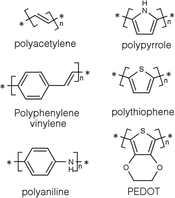
Conducting polymers (CPs) are a subset of a larger group of materials called organic polymers that exhibit semiconducting or conducting properties.8,9 A polymer is, according to the International Union of Pure and Applied Chemistry (IUPAC), a macromolecule with a high relative molecular weight and composed of multiple “poly” repetitive units “mers”. These repetitive units are based on molecules with low relative molecular weight.10 For a long time, polymers were regarded as electrically insulating materials and were mostly used for insulating electrical components.8,11 However, it all changed around thirty five years ago when some polymers showed semiconducting properties in the accidental discovery of doped polyacetylene (Fig. 1) by Shirakawa and co-workers.12 They quickly noticed that the conductivity of polyacetylene was dependent on the level of oxidation and that it can be tuned to cover the full range from insulators to metals.13 Indeed for harnessing and developing this concept, they were awarded the 2002 Noble prize in chemistry.14Since then, CPs have become the focus of many studies in the fields of material science and energy due to their interesting and tuneable properties. The outstanding electrical and optical properties of CPs are a result of their intrinsic chemical structure. They are conjugated and have a backbone of adjoining sp2 hybridised orbitals, hence, delocalised π electrons are formed along their backbone.15,16 One of the most studied CPs is polyaniline (PANi) as well as polythiophenes, polypyrrole, and polyphenylene vinylene (Fig. 1).17–20
In order to understand the mechanism by which CPs exhibit their electric conductivity, band theory is usually applied.9 In the following sections band theory will be discussed in light of quantum theory and molecular orbital theory.
Band theory explanation based on quantum theory
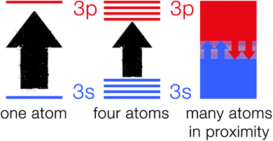
The explanation of atomic spectra by quantum theory makes it a very useful tool in the process of understanding the band theory.21,22 According to quantum mechanics, atomic particles (e.g. electrons) can only occupy well-defined and explicit energy levels.23 As electrons hop from one energy level to another allowed energy level, they give rise to narrow line widths.24 As atoms in a crystalline solid are in close proximity to one another and chemically bonded to their surrounding atoms, they cannot be viewed as isolated particles.25 This is due to the electrons on an atom sensing the electric field generated by electrons on other surrounding atoms. Hence, fusing of the discrete energy levels into a broad energy band occurs which is strongly dependent on the nature of the chemical bond in the solid.26 Fig. 2 shows a schematic of 3s and 3p orbitals for a single sodium atom that overlap to become bands overlapping in energy. These bands are linked to the whole crystal rather than to single atoms.Band theory explanation based on molecular orbital theory
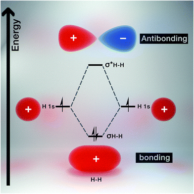
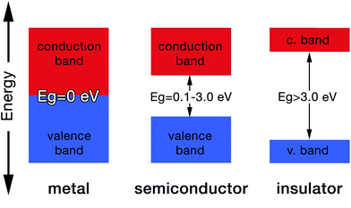
Molecular orbital theory gives chemical insight into band theory. For any two given atoms (e.g. hydrogen as it is the simplest of atoms, Fig. 3), their atomic orbitals can overlap with one another when they come close to each other. As a result, two molecular orbitals known as the bonding and antibonding orbitals are formed.26 These molecular orbitals are delocalized over both atoms. The energy of the bonding molecular orbital (σ) is lower than the individual hydrogen atomic orbital, while the antibonding molecular orbital energy (σ*) is higher.As a result, the molecular orbital that possess the lowest energy forms the bond between the two atoms, hence it is termed the bonding orbital, and when these overlap is called the valence band, while the molecular orbital with the highest energy (i.e. antibonding orbital) when overlapped is called the conduction band (Fig. 4). The valence band (VB) represents the highest occupied molecular orbital (HOMO) and the conduction band (CB) represents the lowest unoccupied molecular orbital (LUMO).27
The gap between the HOMO and LUMO is called the energy gap (Eg) which is the range of energies that is unavailable to electrons. It is also known variously as “the fundamental energy gap”, the “band gap”, or the “forbidden gap”.9,21 The conjugated structure of CPs has been found to be essential to permit the formation of delocalized electronic states.16 The degree of delocalization determines the size of the energy gap and hence the conductivity of the CP (i.e. metallic, semiconducting or insulating, Fig. 4).27 This conjugation and alternation of bonds provide a continuous overlap of p-orbitals to form π–π* hybrid orbitals that allows charge carriers (e.g. electrons, holes) to move freely along the polymer structure in a process that mimics the movement of electrons in metals.28 Table 1 shows the conductivities of some popular CPs.29
| Polymer | Band gap (eV) | Conductivity (S cm−1) |
|---|---|---|
| a Conductivity and band gap values are from different references. | ||
| Polyacetylene | 1.5 | 103 to 1.7 × 10⁵ |
| Poly(p-phenylene-vinylene) | 2.5 | 3 to 5 × 10³ |
| Polyaniline | 3.2 | 30–200 |
| Polypyrrole | 3.1 | 102 to 7.5 × 10³ |
| Polythiophene | 2.0 | 10 to 103 |
| Poly(3,4-ethylene-dioxythiophene)a | 1.4–2.5 (ref. 30) | 103 (ref. 31 and 32) |
However, most CPs lack intrinsic charge carriers, and thus require partial oxidation with electron acceptors (i.e. anions) or partial reduction with electron donors (i.e. cations).28 Both partial oxidation and reduction are referred to as p-doping and n-doping respectively.20 Charged defects, such as polarons, bipolarons and solitons, are introduced into the polymer structure as a result of the doping process.28 These defects then play the role of charge carriers. This is analogous to the p and n doping of Si.
The mechanism by which these charged defects are formed is shown in Fig. 5. At first, the addition/removal of electrons to the bottom of the conduction band, or from the top of the valence band, makes the conduction/valence band partially filled, and hence facilitates the creation of a radical anion/cation (i.e. polaron).33 Injection of states into the band gap from the bottom of the conduction band or the top of the valance band results from the creation of the polarons. Further addition/removal of another electron results in the formation of a dianion/dication (i.e. bipolaron) with a lower total energy.33 Solitons are a special type of charged defect that are unique to CPs with a degenerate ground state (e.g. trans-polyacetylene) and are not present in CPs like polyaniline (PANi), polythiophene, poly(3,4-ethylenedioxythiophene) (PEDOT) and polypyrrole.28,33 They are formed when bipolarons further lower their energy state by dissociating into two solitons at half of the energy gap.33
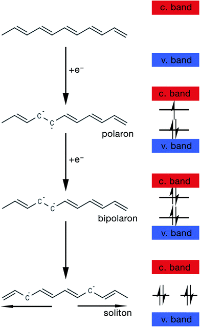 | ||
| Fig. 5 Schematic showing the steps of formation of a polaron, bipolaron and soliton in trans-polyacetylene. | ||
Synthesis
Essentially, there are two main methods of synthesising a CP namely; electrochemical oxidation and chemical oxidation of a monomer.34,35 However, other exotic methods such as enzyme-catalysed and photochemical polymerisation can also be used.36,37 Typically, polymerisation starts with the monomers as the starting material that results in low molecular weight oligomers. These oligomers undergo further oxidation to form polymers at potentials lower than the monomer's oxidation potential.34 This review will discuss mainly the chemical and electrochemical polymerisation methods. In the case of chemical polymerisation, chemical oxidants such as ammonium persulfate [(NH4)2S2O8], ferric nitrate [Fe(NO3)3] and ferric chloride (FeCl3) are used to polymerise the monomers so that the polymer precipitates out of solution.17,32,34,38 On the other hand, in the case of electrochemical polymerisation, a potential is applied at an electrode immersed in a monomer solution in order to oxidise the monomers so that the polymer electrodeposits onto the electrode.4,39Chemical polymerisation
Polymerisation occurs when monomers are oxidised by oxidising agents which initiate the polymerisation reaction. Typical oxidising agents are ammonium persulfate and ferric chloride which have oxidation potentials of E0 = 1.94 V and 0.77 V respectively.40 Although, ferric chloride has the lowest oxidation potential compared to the other oxidizing agents, it is still a very useful oxidant which has been reported to yield up to a 200![[thin space (1/6-em)]](https://www.rsc.org/images/entities/char_2009.gif) 000 molecular weight polyaniline chain.41 Some CPs, such as aniline-based CPs, require excess protons and therefore relatively acidic pH conditions (pH < 3) are used for polymerisation.42 The use of excess protons is related to the mechanism of polymerisation as well as minimising the formation of undesired branched products.17,43–45
000 molecular weight polyaniline chain.41 Some CPs, such as aniline-based CPs, require excess protons and therefore relatively acidic pH conditions (pH < 3) are used for polymerisation.42 The use of excess protons is related to the mechanism of polymerisation as well as minimising the formation of undesired branched products.17,43–45
Electrochemical polymerisation
Typically, three techniques are used in electrochemical polymerisation; namely potentiostatic (the application of a constant voltage), potentiodynamic (a variable current and voltage), or galvanostatic (a constant current) at an electrode in a solution of the relevant monomer.19,36,46 Electrochemical polymerisation is typically achieved by using a three electrode configuration (i.e. counter, reference, and working electrodes). The polymer is then deposited onto the working electrode during the polymerisation process. Usually, the working electrode is made out of platinum, glassy carbon or indium tin oxide (ITO). Recently, a novel sandwich cell setup has been developed by Abdelhamid et al. where a flexible carbon fabric was placed between two ITO electrodes upon which PEDOT was electropolymerised.4 Electrolytes such as inorganic acids or protic ionic liquids (PILs) are typically required for the polymerisation of PANi however, they are not essential for the polymerisation of PEDOT and polypyrrole.43 As in the case of chemical polymerisation, the presence of protons plays many roles such as providing a sufficiently acidic pH thus avoiding excessive branching of undesired products as well as generating doped forms of the CP.17,43,44Polymerisation mechanism
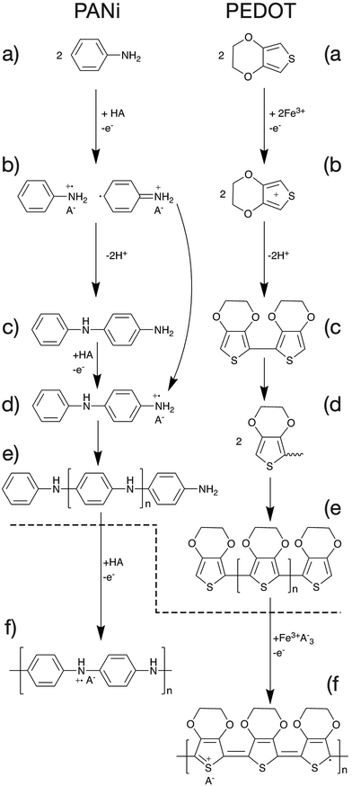
The mechanism of polymerisation of PANi and PEDOT will be discussed in this article as examples of CP polymerisation. In general, the overall polymerisation reaction can be classified into two major steps (Fig. 6). First, the monomers are polymerised through oxidative polymerisation to give an undoped polymer (Fig. 6a–e). Then the neutral polymer is doped as a result of the excess acid or oxidant in the case of PANi or PEDOT respectively (Fig. 6f).47The oxidative polymerisation process can be broken down into three sub-steps;
(a) monomer oxidation into a radical cation (Fig. 6a and b).47,48
(b) Radical coupling and re-aromatisation yielding a dimer species (Fig. 6b and c).49
(c) Chain propagation (Fig. 6c–e).
Tailoring the polymer nanostructure
Producing conducting polymer nanostructures has been extensively researched due to improved properties over their bulk counterparts and their potential applications.50,51 On the contrary to bulk CPs, generally, nano-structured CPs exhibit higher electrical conductivity, larger surface area, shorter path length for ion transport and improved electrochemical activity.52 Because of these superb properties they show promise in energy applications as well as sensing.53–55 Nano-structuring CPs can be achieved through many different methods. These can be categorised under two main approaches, namely template-based and template free methods. Both methods will be discussed briefly in this article.Template-based synthesis
Template-based nano-structuring is utilised because it is an efficient and easy method to produce a highly controlled CP nano-structure. In template-based methods, a template is used to direct the polymer to grow into certain shapes and sizes. These templates vary from hard to soft templates where the hard templates rely on physically moulding the CPs into shapes, while the soft templates mainly rely on self-assembly of the polymer.In the case of the nano-sized channelled templates, Lee et al. were able to electropolymerise PEDOT with MnO2 into nanowires via deposition into an AAO template.60 The composite nanowire had a coaxial structure with PEDOT as the shell and MnO2 as the core. Fig. 8 shows the mechanism and steps of forming nanowires from CPs.
 | ||
| Fig. 9 Schematic illustrating the steps by which the soft template method produces CP nanoparticles. | ||
Micro-emulsion (i.e. oil-in-water) polymerization has the advantage of controlling the size of the CP nanoparticles. Monodispersed polypyrrole nanoparticles were achieved by Jang et al. via micro-emulsion with alkyltrimethylammonium bromide cationic surfactants.62 They found that the optimum carbon chain length of surfactants that is most suitable for micro-emulsion polymerization should be from C6 to C16. That is because alkyl chains shorter than C6 exhibit weak hydrophobic interactions, while alkyl chains longer than C16 lead to the failure in forming self-assembled nanostructures due to their high viscosity. Furthermore, Guo et al. controlled the morphology of PANi by using sodium dodecyl sulphate (SDS) in a HCl solution.63 They discovered that the morphology of the self-assembled nanostructures is pH dependant. By varying the conditions of polymerisation, such as pH and concentration of surfactants, they were able to produce different PANi nanostructures like granules, nanofibres, nanosheets, rectangular nanotubes, and fanlike/flowerlike aggregates.
One advantage of the micro-emulsion polymerization process is that with little modification, nanocapsules, nanocomposite, and mesoporous structures can be produced. Jang et al. exploited this and produced polypyrrole nanocapsules by synthesising a soluble polypyrrole core then introducing different initiators with different oxidation potentials in order to cross-link the polypyrrole into a shell (Fig. 10).64 At first, a polypyrrole core that is soluble in alcohol (due to its linear structure) was generated by using cupric chloride (CuCl2) which has a relatively low oxidation potential (E0 = +0.16 V). This was followed by the generation of an insoluble cross-linked polypyrrole shell by using ferric chloride (FeCl3) which has a higher oxidation potential (E0 = +0.77 V). Finally, by adding an excess amount of methanol to etch the polypyrrole core as well as the surfactants, polypyrrole cross-linked nanocapsules were obtained. In this work the nanocapsules were then carbonised to produce carbon nanocapsules. In a different approach, Jang et al. was able to produce PEDOT nanocapsules via surfactant-mediated interfacial polymerization (SMIP).65 In the SMIP process, the initiator couples with the surfactant micelles due to electrostatic interactions with the cations of the initiator, thus permitting the initiator to react with the monomer at the micelle/water interface to produce hollow PEDOT nanocapsules.
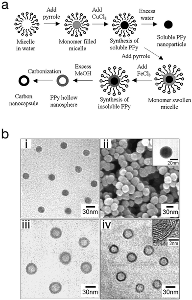 | ||
| Fig. 10 (a) Schematic illustrating the fabrication of polypyrrole nanoparticles, hollow nanocapsules and their carbon derivatives. (b) SEM and TEM micrographs of (i) polypyrrole nanoparticles, (ii) linear polypyrrole/cross-linked polypyrrole core–shell nanoparticles, (iii) polypyrrole nanocapsules, and (iv) carbon nanocapsules. Reproduced from ref. 64 with permission from The Royal Society of Chemistry. | ||
On the other hand, reversed micro-emulsion (i.e. water-in-oil) polymerisation has been reported to produce CP nanostructures such as monodispersed nanoparticles, nanotubes and nanorods. The morphology is controlled via manipulating the ion–surfactant interaction. Using this method, polypyrrole nanotubes were produced through chemical polymerisation in a reversed emulsion of sodium bis(2-ethylhexyl) sulfosuccinate (AOT) in a non-polar solvent (Fig. 11).66,67 At first, the AOT reverse micelles were formed through the interaction between aqueous FeCl3 solution and the AOT. Then, pyrrole was introduced into the reverse cylindrical micelle phase, thus rapidly polymerising due to the presence of iron cations within the reverse cylindrical micelles. This resulted in the formation of polypyrrole nanotubes. Finally, the AOT and the unreacted reactants were removed by rinsing in an excessive amount of ethanol. A similar method was used by Zhang et al. to produce PEDOT nanotubes,68 as well as Jang et al. to generate PEDOT nanorods via chemical polymerisation directly onto the micelle.67
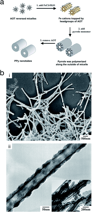 | ||
| Fig. 11 (a) Schematic illustrating the fabrication of polypyrrole hollow nanotubes via reversed micelle polymerisation. (b) (i) SEM micrograph of polypyrrole nanotubes, and (ii) TEM micrograph of a polypyrrole nanotube. Reproduced from ref. 67 with permission from The Royal Society of Chemistry. | ||
Template-free synthesis
The template-free method is considered to be the simplest and cheapest of methods as it requires no template and no post treatment to remove the template.69 It was discovered that PANi could be polymerised into nanotubes without the use of templates but instead by conventional chemical polymerisation techniques in the presence of β-naphthalene sulfonic acid (β-NSA) as the dopant.70 Despite the fact that control over the morphology of the CP nanostructures is poor in comparison to template-based methods, the morphology of template-free produced CPs are found to be strongly dependant on the monomer's structure, dopant, oxidant, and the polymerisation conditions.51,69Furthermore, CP nanofibres were produced and morphologically controlled via an electrochemical approach. Kalantar-zadeh et al. developed template-free PANi nanofibrils via a multi-potential electropolymerisation technique.53 Fig. 12 shows SEM micrographs of the PANi nanofibril mat generated via this method. At first, nucleation sites were generated onto the electrode (e.g. ITO glass electrode) by biasing the potential at 0.76 V for 90 s followed by stepping down the potential to 0.73 V for 600 s. Finally, the potential was lowered further to 0.68 V for another 1800 s to continue the growth of the fibrils. They found that the nanofibrils exhibited a tapered shape from the bottom to the top.
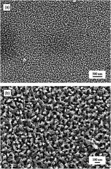 | ||
| Fig. 12 (a) SEM micrograph of a PANi nanofibril mat on an ITO glass electrode, and (b) higher magnification of picture (a). Reprinted from ref. 53 with permission from Elsevier. | ||
Polypyrrole nanowires were produced via cathodic electropolymerisation by Kwon et al.71 by biasing the potential at 0.6 V (vs. SCE) and stirring the reaction solution via a magnetic stirrer at ∼700 rpm during the electropolymerisation. They studied the effect of time, monomer concentration and dopant concentration on the morphology of the polypyrrole nanostructures (Fig. 13). Their method utilised an electrochemically generated oxidant (NO+), via reduction of nitrate anion, in order to oxidise pyrrole monomer at the electrode surface.
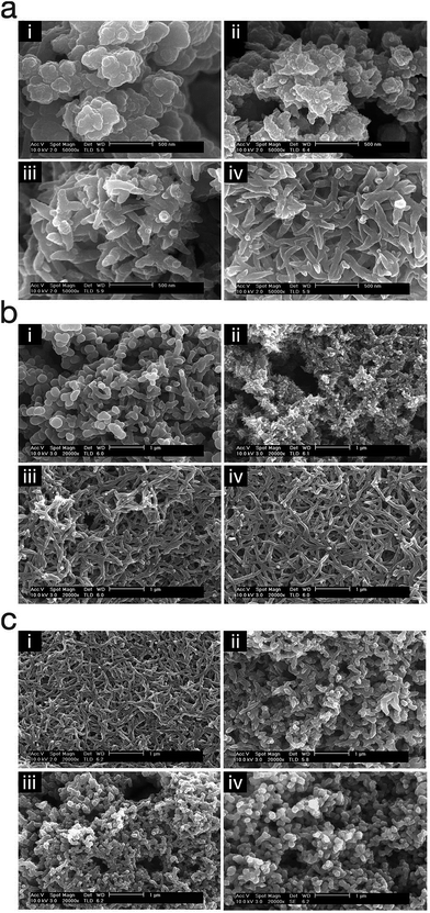 | ||
| Fig. 13 SEM micrographs of polypyrrole nanostructures electropolymerised under different conditions; (a) polymerisation time (i) 1 min, (ii) 2 min, (iii) 3 min, and (iv) 4 min, (b) pyrrole concentration (i) 0.025 M, (ii) 0.05 M, (iii) 0.10 M, and (iv) 0.20 M, and (c) dopant concentration (i) 0.20 M, (ii) 0.40 M, (iii) 0.60 M, and (iv) 0.80 M. Reproduced from ref. 71 with permission from The Royal Society of Chemistry. | ||
This study showed that the polypyrrole started to deposit on the electrode as nanospheres and then changed gradually into nanowires (Fig. 13a). Also, the monomer/dopant concentration study showed that the polymerisation kinetics, that determine the morphology of the nanostructures, is affected by the activity of the radical cations (Fig. 13b and c).71
Applications
Due to the outstanding chemical, physical and economic advantages of CPs, such as wide ranging electrical conductivity, mechanical flexibility, self-healing, facile production, easy nano-structuring, high surface area to weight ratio, and low cost, they have been incorporated in many applications.34,72 For each different application, the method of polymerisation, the morphology and properties of the CPs can be tailored to meet the requirement of the specified application.73 Therefore, CPs are employed in a wide range of applications (Fig. 14), such as the semiconductor industry, corrosion protection, photovoltaic devices, or electrocatalysis to name a few.74,75 Nevertheless, their applications in the field of energy will be the focus of the rest of this review.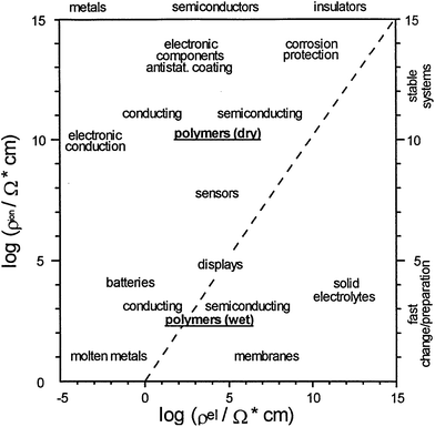 | ||
| Fig. 14 Double logarithmic plot outlines the applications of CPs as a function of ionic (y-axis) and electronic resistances (x-axis). Reprinted from ref. 74 with permission from Elsevier. | ||
Energy storage devices
Nanostructured CPs are utilised as materials for electrochemical energy storage devices, such as electrolytic capacitors “supercapacitors” and batteries (e.g. Li-ion batteries) due to many reasons.55,76 Firstly, their high surface area in contact with the electrolyte, allows for high charge/discharge rates. Secondly, their short path lengths for ionic transport allows for faster ionic diffusion within the CP network. Lastly, they exhibit a high tolerance towards the strain of an electrochemical reaction, hence improving the cycle life of the device.50 However, CPs expand during the doping process and shrink when de-doped. This repetitive expansion/shrinkage behaviour, due to cycling, leads to structural breakdown in the longer term. Nevertheless, the facile micro- and nano-structuring of CPs granted scientists many flexible and efficient routes to design the most efficient conducting polymer structures and to improve their electrochemical energy storage ability.77 The following is a discussion on the application of CPs in supercapacitors and battery technologies.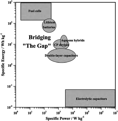 | ||
| Fig. 15 Ragone plot illustrates different types of energy-storage devices as a function of specific power and energy. Reprinted from ref. 78 with permission from Elsevier. | ||
In this rapidly evolving research field, capacitors were fabricated to provide much more capacitance (102 to 103 F) and for that reason they were called supercapacitors. Such supercaps typically utilised high surface area carbon based electrodes.80 Basically, these are composed of two electrodes connected in series with a conducting liquid media in between. The supercaps operate by utilising the double-layer capacitance and hence are often known as electrochemical double-layer capacitors (EDLC). The capacitance is stored as accumulated charge in the electrical double-layer at the electrode/solution interface.
Pseudocapacitors are another type of supercapacitor, in which the capacitance is stored as accumulated charge in the bulk of a redox material as a result of a redox reaction. This redox reaction is rapid and behaves like a capacitive charge.19,81 In a pseudocapacitor, the bulk of the material is exposed to the redox reaction on the contrary to the EDLC where just the surface layer participates in the process. This enables pseudocapacitors to hold a greater amount of capacitance per weight in comparison with an EDLC. However, the EDLC has faster kinetics because only the surface is involved. CPs are a good example of materials that are being used as pseudocapacitors.
Fig. 16 illustrates the difference between EDLCs and CP-based supercaps. Due to their structure that aids fast ionic sorption/desorption, carbon-based supercaps (i.e. EDLCs) exhibit high power capabilities.82 CPs are expected to improve the energy storage devices as a result of the redox reaction which they undergo in order to store charge in the bulk of the material and hence increasing the energy stored. However, the slow diffusion of ions within the bulk of the CP electrode leads to relatively low power (i.e. low rate of charge/discharge). Nevertheless, CPs have many advantages which counteracts such a drawback and they are still proposed to be able to bridge the gap between batteries and EDLCs as CP electrodes exhibit faster electron transfer kinetics than other materials, such as metal oxides.82 As well as their previously discussed properties, they have the potential to be specifically engineered into specific nanostructures in order to optimise CP electrodes for maximum capacity uptake. Such optimisation can be achieved by manipulating the morphology and surface area per weight of the CP electrodes, as the capacitance of any given capacitor is proportional to the surface area of the electrode (eqn (1)),
 | (1) |
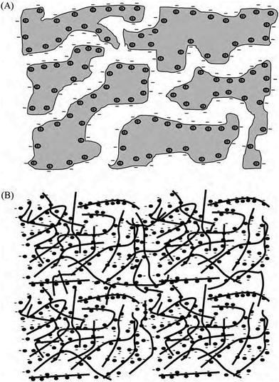 | ||
| Fig. 16 Illustration of the mechanism of charging of (a) EDLCs (carbon), and (b) pseudo-capacitor (CPs). Reprinted from ref. 78 with permission from Elsevier. | ||
CPs-based supercaps can be organised under three different categories depending on their setup configuration:83,84
• Type I (symmetric) in which both electrodes are the same p-dopable CP (e.g. PEDOTp|PEDOTp).
• Type II (asymmetric) in which two different p-dopable CPs are used for each electrode (e.g. PEDOTp|PANip).
• Type III (symmetric) in which the same CP is used for both electrodes where the p-doped form is for the positive electrode and the n-doped form is for the negative electrode (e.g. PEDOTp|PEDOTn).
The most attractive category is the type III-based device where it is composed entirely of the same CP with different doping states. In theory, both electrodes would be doped (i.e. n-doped and p-doped for each electrode) in the charged state, hence the electrodes should be highly conductive.85 As a result, the potentials required to release the charge is very high (i.e. ≥3 V) compared with the other two types.86 This high discharging potential should lead to high specific energy and power according to eqn (2).87 However, the practical performance of these types of CP supercaps is not as good as theorised due to the difficulty of the n-doping process. The high impedance at the highly negative potential, at which the n-doping takes place, leads to chemical instabilities and hence the difficulty of n-doping such CPs.
 | (2) |
The three CPs mainly used as supercaps electrode materials, are PANi, PEDOT, and polypyrrole. In the case of PANi, extensive studies have been undertaken to test it as a supercapacitor material.83,88 Wu et al. fabricated PANi electrodes electrochemically for supercaps via dissolving aniline into acidic suspensions of negatively charged multi-walled carbon nano-tubes (MWNTs).42 Then, the MWNT–PANi composite films were polymerised into a nanoporous structure via galvanostatic polymerisation (Fig. 17). In comparison to PANi films, the MWNT–PANi composite films exhibited similar electrochemical response rate. Significantly, however, the MWNTs–PANi composite were more electrically conducting and mechanically stable. Furthermore, the composite material's capacitance per surface area was found to be 3.5 F cm−2 which surpassed the non-composite material's capacitance (i.e. 2.3 F cm−2).42
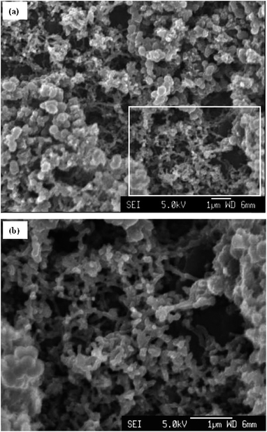 | ||
| Fig. 17 SEM micrographs of (a) the surface of a MWNT–PANi polymerised via galvanostatic polymerisation at 1 mA for 5 min, and (b) higher magnification of the rectangle in (a), showing the nanoporous network of MWNTs–PANi composite. Reproduced from ref. 42 with permission from The Royal Society of Chemistry. | ||
PEDOT was also explored as a supercapacitor electrode material by Snook et al.89 The CP was electropolymerised via potentiostatic oxidation of the monomer at 1.0 V vs. Ag/AgCl (3 mol L−1 KCl). At this potential, and a deposition charge of 60C cm−2, PEDOT grew as a coherent and porous film on a Pt electrode with high current efficiency whereas polypyrrole grew into a dense film under the same conditions. The PEDOT film was allowed to grow up to 0.5 mm thickness. These films showed a linear increment in capacitance and a practical capacitance of 5 F cm−2, as measured by both cyclic voltammetry (CV) and electrochemical impedance spectroscopy (EIS). The specific (areal) capacitance of PEDOT was found to be much higher than PANi's (∼2.0 F cm−2) and polypyrrole's (≤1.0 F cm−2). Fig. 18 shows the SEM image of the electropolymerised PEDOT plus a plot of the electrode specific capacitance as a function of polymerisation charge.
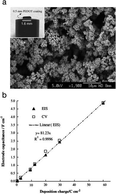 | ||
| Fig. 18 (a) SEM micrograph of PEDOT electropolymerised via potentiostatic polymerisation (deposition charge: 30C cm−2). Inset: photograph of a PEDOT film (60C cm−2) on a Pt disc electrode). (b) Plot of the electrode specific capacitance as a function of polymerisation charge. Values measured by electrochemical impedance spectroscopy (EIS) and cyclic voltammetry (CV) are both presented. Reprinted from ref. 89 with permission from Elsevier. | ||
Firstly, one of the most widely proposed materials for Li-ion battery cathodes is sulphur due to its high theoretical specific capacity (1672 mA h g−1), while the energy density of the Li-ion/S battery is 2600 W h kg−1.92 Two major drawbacks are associated with the use of sulphur as a cathode material. The first one is low specific capacitance of the sulphur due to its high electrical resistivity. The second obstacle is the shuttle effect where polysulfide intermediates form during the charging/discharging process which can dissolve into the electrolyte and diffuse to the anode. When the polysulfide species reach the anode, they react with lithium and form insoluble Li2S and Li2S2 at the anode, thus leading to fast capacity fading.93 Many attempts to overcome these challenges have been undertaken such as loading the sulphur into porous carbon materials via ball milling and high temperature infiltration.94 These porous carbon materials, developed by Nazar et al., serve as conducting networks for electron transport as well as an encapsulation matrix for the polysulfide intermediates.95 Nevertheless, these types of composites are not efficient in keeping the soluble polysulfide species out of the electrolyte for long giving a poor cycle life.
Therefore there is a need for a material that can improve the entrapment of polysulfides while at the same time, is conductive, and hence CPs rise as a suitable candidate. The utilisation of CPs to help encapsulate the sulphur was explored by Cui et al.96 These authors used encapsulated carbon/sulphur particles with PEDOT:PSS† (Fig. 19).
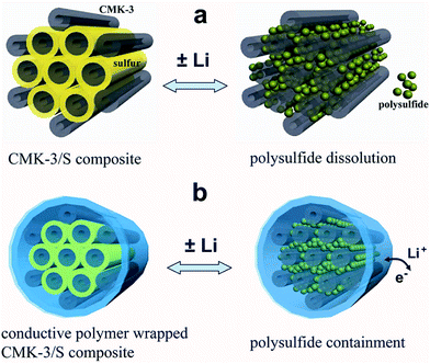 | ||
| Fig. 19 Illustration of the encapsulation of carbon/sulphur particles with PEDOT:PSS for improving polysulfides encapsulation. (a) Carbon/sulphur particles without PEDOT:PSS coating (grey: carbon, yellow: sulphur, and green: polysulfides) and the polysulphides leak out of the carbon matrix during charge/discharge process. (b) With a PEDOT:PSS coating (blue colour) where the polysulfides are encapsulated within the composite and therefore lithium ions and electrons can move in and out. Reprinted with permission from ref. 96 Copyright (2011) American Chemical Society. | ||
This resulted in the reduction of polysulfide dissolution, and hence improvement in the battery performance. They reported an increase of ∼10% in the initial discharge capacity (1140 mA h g−1) compared with the non-coated carbon/sulphur particles. Furthermore, capacity retention was notionally improved from ∼60% per 100 cycles to ∼85% per 100 cycles and the coulombic efficiency increased from 93% to 97%.
Recently, Chen et al. utilised CPs in sulphur cathodes with a different approach. They generated sulphur-coated PEDOT core/shell nanoparticles (10–20 nm) via a membrane assisted precipitation technique (Fig. 20).97 The nanosize of the sulphur particles led to a high specific surface area and the PEDOT provided the conductive matrix for electron transport. The PEDOT also served as an effective encapsulation shell to entrap the polysulfides and prevent dissolution into the electrolyte. As a result, the sulphur cathode composite exhibited excellent cyclic durability and performance with an initial discharge capacity of 1117 mA h g−1 and a capacity retention of 83% per 50 cycles.97
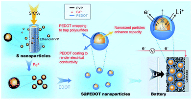 | ||
| Fig. 20 Illustration of the preparation of sulphur/PEDOT core/shell nanoparticles and their application as cathode materials. On the left, the synthesis of sulphur nanoparticles via a membrane-assisted precipitation method is shown. In the middle, the encapsulation of the sulphur nanoparticles with a PEDOT shell via oxidation polymerisation. On the right, sulphur/PEDOT nanoparticles as the cathode material that allows electron transport and Li ions to diffuse while limiting the polysulfide dissolution is shown. Reprinted by permission from Macmillan Publishers Ltd: Scientific Reports,97 copyright (2013). | ||
Furthermore, the anode in the Li-ion battery is usually made out of graphite but it has a very low specific capacity of ∼370 mA h g−1 that does not meet the high energy supplied from the lithium cathode. As a result, silicon has been proposed to replace graphite as an anode material because of its high theoretical specific capacity of ∼4200 mA h g−1, its relatively low discharge potential (∼0.5 V vs. Li/Li+), and its environmental safety.98 Nevertheless, silicon has some limitations due to volume expansion that reaches up to ∼400% during the lithiation process.99 This massive volume expansion results in structural fracture, and hence loss of electrical contact as well as breaking and re-formation of an unstable solid electrolyte interface (SEI) in the subsequent cycles which consumes the electrolyte.3
In order to overcome such limitations, nanostructured silicon materials were explored as a replacement for macro- and microstructured silicon100,101 and the use of such nanomaterials led to longer cycling life.101 Moreover, anodes, in slurry form, were fabricated from Si nanoparticles and various polymeric binders such as, polyacrylic acid (PAA), polyvinylidene difluoride (PVdF), and carboxyl-methyl cellulose (CMC) were used in order to improve the cycle life.102,103 The Si/PAA and Si/CMC composites exhibited an improved cycle life due to the binding between the functional groups on the polymers and the oxide layer on the silicon particles.
In the last few years, many attempts to utilise CPs with Si anodes were undertaken. A special variant of CPs was tested by Liu et al. in order to overcome some of the Si anode drawbacks.103 Their polyfluorene-type polymers served as a conductive binder to overcome the volume expansion problem. Recently, Cui et al. achieved a high performance Li-ion battery by incorporating a PANi hydrogel into the silicon anode.1 They encapsulated the Si nanoparticles within the PANi 3D porous network via in situ polymerisation, which is highly scalable (Fig. 21). The CP served as a conductive network for fast electron and ion transport as well as providing the proper space for the Si to expand. They reported 5000 cycles with high capacity retention (∼90%). The PANi network was polymerised and doped with phytic acid which allowed the cross-linking of the polymer to form a gel which also aided the PANi network to attach to the silicon surface.
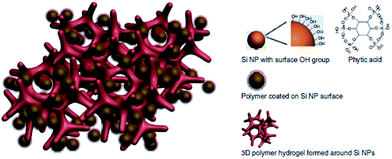 | ||
| Fig. 21 Illustration of the 3D porous Si nanoparticles/conductive polymer hydrogel composite electrode. PANi hydrogel framework encapsulate the Si nanoparticles. Si nanoparticles are coated with the PANi layer either through interactions between surface –OH groups and the phosphonic acids in the cross-linker phytic acid molecules (right column), or the electrostatic interaction between negatively charged –OH groups and positively charge PANi due to phytic acid doping. Reprinted by permission from Macmillan Publishers Ltd: Nature Communications,1 copyright (2013). | ||
Fuel cells
Typically in fuel cells, noble metal nanoparticles such as platinum and platinum based composite materials are utilised via immobilisation on high surface area substrate materials in order to serve as cathodes. These cathodes are used for the oxygen reduction reaction (ORR), which is an important half-cell reaction in fuel cells, because of their high activity and high current density.5,104 However, the use of such nanomaterials has some drawbacks, thus limiting their application in fuel cells. Such drawbacks are mainly cost, poor mechanical attachment in the case of composite electrodes and the susceptibility to dissolution.6 On the other hand, CPs and, especially, PEDOT have exhibited good non-metal based catalytic activity and is regarded as an alternative to Pt for the ORR which has been demonstrated by many groups.105–108 The idea of replacing the precious and expensive Pt with CPs is highly attractive.The ORR follows two different pathways depending on the nature of the catalyst on which the reaction is taking place. The first pathway (eqn (3)) is a 4-electron step where oxygen is completely reduced into hydroxide in one direct step as demonstrated by Winther-Jensen et al.105 The second pathway is two consecutive 2-electron steps where oxygen is reduced to peroxide then to hydroxide (eqn (4a) and (4b)).
| O2 + 4e− + 2H2O → 4OH− | (3) |
| O2 + 2e− + H2O → OH− + O2H− | (4a) |
| O2H− + 2e− + H2O → 3OH− | (4b) |
The first pathway is the desired one as it is kinetically fast on the contrary to the second pathway which is sluggish and inhibits the performance of any fuel cell. Winther-Jensen et al. were able to fabricate a highly catalytically active PEDOT film by vapour deposition,105 where oxygen could be reduced to hydroxide through the desired direct 4-electron step. Moreover, they explored the effect of the polymerisation method on the catalytic activity of PEDOT towards the ORR.106 They found that the catalytic pathway for the ORR is significantly dependant on the polymerization method used to generate the polymer. Interestingly, for PEDOT prepared via conventional electrochemical methods, the ORR only proceeded via the 2-electron steps pathway and is still not fully understood.
Recently, a novel technique was employed by Abdelhamid et al. to electropolymerise PEDOT from an ionic liquid onto a carbon cloth using a sandwich cell setup (Fig. 22).4 The use of this approach prevented PEDOT from diffusing back into the reaction solution as observed using a conventional three electrode cell setup in a large volume of electrolyte. The resultant PEDOT electrode exhibited activity towards the ORR over a wide range of pH with less generation of the peroxide intermediate compared with the same material polymerised in acetonitrile while also being tolerant to the presence of methanol in the electrolyte. It was found that the cell setup in addition to the polymerisation solvent affected the morphology of the polymer deposited onto the substrate and hence the ORR activity of the produced PEDOT electrode.
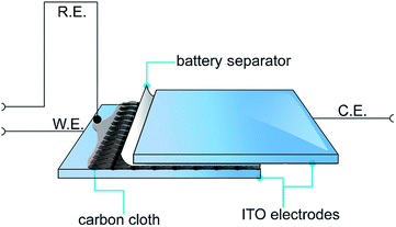 | ||
| Fig. 22 Illustration of the electropolymerisation method used to polymerise PEDOT onto carbon cloths. The carbon cloth is wetted with EDOT in C4mpyrTFSI IL or 1 M LiTFSI in acetonitrile and covered with a battery separator from one side and then sandwiched between two ITO–glass electrodes. Reprinted by permission from Wiley: ChemPlusChem,4 copyright (2015). | ||
Conclusions
The ability of conducting polymers to be structurally engineered in order to meet specific applications has led to their wide utilisation in many important technological fields, such as energy storage and generation. Their structures can be varied from nanoparticles, nanowires, nanotubes, and nano-hollow capsules by controlling the polymerisation conditions. Also, their excellent chemical and physical properties, such as high surface area, short path lengths for electronic and ionic transport, their high tolerance towards the strain of an electrochemical reaction, has promoted them to be among the most widely studied materials for energy applications. These include supercapacitors, lithium-ion batteries and fuel cells. Given that CPs have the potential to be manufactured on a large scale and are solution processable makes them particularly attractive for applications that require flexibility such as wearable electronics and structural batteries that can be employed on the panels of vehicles.Acknowledgements
MEA acknowledges the CSIRO for provision of a PhD stipend. AOM gratefully acknowledges funding from the Australian Research Council through a Future Fellowship (FT110100760). GAS acknowledges the funding from the CSIRO Office of the Chief Executive Julius Career Award.Notes and references
- H. Wu, G. Yu, L. Pan, N. Liu, M. T. McDowell, Z. Bao and Y. Cui, Nat. Commun., 2013, 4, 1943 Search PubMed.
- L. Hu, H. Wu, S. S. Hong, L. Cui, J. R. McDonough, S. Bohy and Y. Cui, Chem. Commun., 2011, 47, 367–369 RSC; A. Magasinski, P. Dixon, B. Hertzberg, A. Kvit, J. Ayala and G. Yushin, Nat. Mater., 2010, 9, 353–358 CrossRef CAS PubMed.
- D. Aurbach, J. Power Sources, 2000, 89, 206–218 CrossRef CAS.
- M. E. Abdelhamid, G. A. Snook and A. P. O'Mullane, ChemPlusChem, 2015 DOI:10.1002/cplu.201402235.
- Z. Liu, X. Lin, J. Y. Lee, W. Zhang, M. Han and L. M. Gan, Langmuir, 2002, 18, 4054–4060 CrossRef CAS; D. B. Meadowcroft, Nature, 1970, 226, 847–848 CrossRef PubMed.
- B. C. H. Steele and A. Heinzel, Nature, 2001, 414, 345–352 CrossRef CAS PubMed.
- X. Yu and S. Ye, J. Power Sources, 2007, 172, 145–154 CrossRef CAS PubMed; M. S. Wilson, F. H. Garzon, K. E. Sickafus and S. Gottesfeld, J. Electrochem. Soc., 1993, 140, 2872–2877 CrossRef PubMed.
- G. Inzelt, in Conducting Polymers, Springer, Berlin, Heidelberg, 2012, pp. 1–6 Search PubMed.
- K. M. Molapo, P. M. Ndangili, R. F. Ajayi, G. Mbambisa, S. M. Mailu, N. Njomo, M. Masikini, P. Baker and E. I. Iwuoha, Int. J. Electrochem. Sci., 2012, 7, 11859–11875 CAS.
- A. D. McNaught and A. Wilkinson, IUPAC-Compendium of Chemical Terminology-Gold Book, Blackwell Scientific Publications, Oxford, 2nd edn, 1997 Search PubMed.
- A. J. Epstein, J. M. Ginder, F. Zuo, R. W. Bigelow, H. S. Woo, D. B. Tanner, A. F. Richter, W. S. Huang and A. G. MacDiarmid, Synth. Met., 1987, 18, 303–309 CrossRef CAS; A. J. Epstein, J. M. Ginder, F. Zuo, H. S. Woo, D. B. Tanner, A. F. Richter, M. Angelopoulos, W. S. Huang and A. G. MacDiarmid, Synth. Met., 1987, 21, 63–70 CrossRef.
- B. Bolto, R. McNeill and D. Weiss, Aust. J. Chem., 1963, 16, 1090–1103 CrossRef CAS; H. Shirakawa, E. J. Louis, A. G. MacDiarmid, C. K. Chiang and A. J. Heeger, J. Chem. Soc., Chem. Commun., 1977, 578–580 RSC.
- C. K. Chiang, C. R. Fincher, Y. W. Park, A. J. Heeger, H. Shirakawa, E. J. Louis, S. C. Gau and A. G. MacDiarmid, Phys. Rev. Lett., 1977, 39, 1098–1101 CrossRef CAS.
- A. Elschner, S. Kirchmeyer, W. Lövenich, U. Merker and K. Reuter, in PEDOT, CRC Press, 2010, pp. 1–20 Search PubMed.
- C. K. Chiang, M. A. Druy, S. C. Gau, A. J. Heeger, E. J. Louis, A. G. MacDiarmid, Y. W. Park and H. Shirakawa, J. Am. Chem. Soc., 1978, 100, 1013–1015 CrossRef CAS.
- A. J. Heeger, J. Phys. Chem. B, 2001, 105, 8475–8491 CrossRef CAS.
- G. A. Snook, A. I. Bhatt, M. E. Abdelhamid and A. S. Best, Aust. J. Chem., 2012, 65, 1513–1522 CrossRef CAS.
- G. A. Snook and G. Z. Chen, J. Electroanal. Chem., 2008, 612, 140–146 CrossRef CAS PubMed.
- G. A. Snook, G. Z. Chen, D. J. Fray, M. Hughes and M. Shaffer, J. Electroanal. Chem., 2004, 568, 135–142 CrossRef CAS PubMed.
- T. F. Otero, Polym. Rev., 2013, 53, 311–351 CrossRef CAS PubMed.
- J. W. Orton, The Story of Semiconductors, Oxford University Press, 2004 Search PubMed.
- A. A. Levin, Introduction to the Quantum Theory of Solids. Chemical Bonding and Structure of Energy Bands in Tetrahedral Semiconductors, Khimiya, 1974 Search PubMed.
- F. Schwabl, Quantum Mechanics, Springer, 1995 Search PubMed.
- W. Greiner, Quantum Mechanics, Springer-Verlag Tokyo, Inc., 1991 Search PubMed.
- P. W. Atkins, Physical Chemistry, Oxford Univ Press, 6th edn, 1998 Search PubMed.
- P. W. Atkins and R. S. Friedman, Molecular Quantum Mechanics, Oxford University Press, 3rd edn, 2000 Search PubMed.
- Y.-J. Cheng, S.-H. Yang and C.-S. Hsu, Chem. Rev., 2009, 109, 5868–5923 CrossRef CAS PubMed.
- L. Dai, in Intelligent Macromolecules for Smart Devices, Springer, London, 2004, pp. 41–80 Search PubMed.
- L. Dai, J. Macromol. Sci., Rev. Macromol. Chem. Phys., 1999, C39, 273–387 CrossRef CAS.
- L. Groenendaal, F. Jonas, D. Freitag, H. Pielartzik and J. R. Reynolds, Adv. Mater., 2000, 12, 481–494 CrossRef CAS.
- L. Hu, D. S. Hecht and G. Grüner, Appl. Phys. Lett., 2009, 94, 081103 CrossRef PubMed.
- A. Elschner, S. Kirchmeyer, W. Lövenich, U. Merker and K. Reuter, in PEDOT, CRC Press, 2010, pp. 83–89 Search PubMed.
- J. L. Bredas and G. B. Street, Acc. Chem. Res., 1985, 18, 309–315 CrossRef CAS.
- D. J. Sandman, Mol. Cryst. Liq. Cryst. Sci. Technol., Sect. A, 1998, 325, 260–261 CAS.
- Handbook of Conducting Polymers, Third Edition, Conjugated Polymers, Theory, Synthesis, Properties, and Characterization, ed. T. A. Skotheim and J. R. Reynolds, CRC Press LLC, 2007 Search PubMed; G. Inzelt, in Conducting Polymers, Springer, Berlin, Heidelberg, 2012, pp. 149–171 Search PubMed.
- G. G. Wallace, G. M. Spinks and L. A. P. Kane-Maguire, Conductive Electroactive Polymers: Intelligent Materials Systems, 2nd edn, CRC Press, 2002 Search PubMed.
- D. Kumar and R. C. Sharma, Eur. Polym. J., 1998, 34, 1053–1060 CrossRef CAS; S. Annapoorni, N. S. Sundaresan, S. S. Pandey and B. D. Malhotra, J. Appl. Phys., 1993, 74, 2109–2111 CrossRef PubMed.
- A. Elschner, S. Kirchmeyer, W. Lövenich, U. Merker and K. Reuter, in PEDOT, CRC Press, 2010, pp. 67–81 CrossRef CAS; Y. Cao, A. Andreatta, A. J. Heeger and P. Smith, Polymer, 1989, 30, 2305–2311 CrossRef CAS.
- G. A. Snook and A. S. Best, J. Mater. Chem., 2009, 19, 4248–4254 RSC; L. B. Groenendaal, G. Zotti, P.-H. Aubert, S. M. Waybright and J. R. Reynolds, Adv. Mater., 2003, 15, 855–879 CrossRef CAS PubMed; I. Villarreal, E. Morales, T. F. Otero and J. L. Acosta, Synth. Met., 2001, 123, 487–492 CrossRef.
- W. K. Maser, R. Sainz, M. T. Martínez and A. M. Benito, Electroactive polymer-carbon nanotube composites: smart organic materials for optoelectronic applications, 2010 Search PubMed.
- A. G. Green and A. E. Woodhead, J. Chem. Soc., Trans., 1912, 101, 1117–1123 RSC.
- M. Wu, G. A. Snook, V. Gupta, M. Shaffer, D. J. Fray and G. Z. Chen, J. Mater. Chem., 2005, 15, 2297–2303 RSC.
- G. Zotti, S. Cattarin and N. Comisso, J. Electroanal. Chem. Interfacial Electrochem., 1988, 239, 387–396 CrossRef CAS.
- G. A. Snook, T. L. Greaves and A. S. Best, J. Mater. Chem., 2011, 21, 7622–7629 RSC.
- B. Dong, B.-L. He, C.-L. Xu and H.-L. Li, Mater. Sci. Eng., B, 2007, 143, 7–13 CrossRef CAS PubMed.
- T. F. Otero, J. G. Martinez and J. Arias-Pardilla, Electrochim. Acta, 2012, 84, 112–128 CrossRef CAS PubMed; R. Gracia and D. Mecerreyes, Polym. Chem., 2013, 4, 2206–2214 RSC; T. F. Otero and E. De Larreta-Azelain, J. Chim. Phys. Phys.-Chim. Biol., 1989, 86, 131–141 Search PubMed.
- A. Elschner, S. Kirchmeyer, W. Lövenich, U. Merker and K. Reuter, in PEDOT, CRC Press, 2010, pp. 91–111 Search PubMed.
- N. Gospodinova and L. Terlemezyan, Prog. Polym. Sci., 1998, 23, 1443–1484 CrossRef CAS.
- I. Sapurina and J. Stejskal, Polym. Int., 2008, 57, 1295–1325 CrossRef CAS PubMed.
- L. Pan, H. Qiu, C. Dou, Y. Li, L. Pu, J. Xu and Y. Shi, Int. J. Mol. Sci., 2010, 11, 2636–2657 CrossRef CAS PubMed.
- G. Ćirić-Marjanović, in Nanostructured Conductive Polymers, John Wiley & Sons, Ltd, 2010, pp. 19–98 Search PubMed.
- C. G. Wu and T. Bein, Science, 1994, 264, 1757–1759 Search PubMed; Q. Pei and O. Inganaes, J. Phys. Chem., 1992, 96, 10507–10514 CrossRef CAS.
- X. Yu, Y. Li and K. Kalantar-zadeh, Sens. Actuators, B, 2009, 136, 1–7 CrossRef CAS PubMed.
- R. Arsat, X. F. Yu, Y. X. Li, W. Wlodarski and K. Kalantar-zadeh, Sens. Actuators, B, 2009, 137, 529–532 CrossRef CAS PubMed; S. Virji, J. Huang, R. B. Kaner and B. H. Weiller, Nano Lett., 2004, 4, 491–496 CrossRef; A. S. Arico, P. Bruce, B. Scrosati, J.-M. Tarascon and W. van Schalkwijk, Nat. Mater., 2005, 4, 366–377 CrossRef PubMed.
- P. Simon and Y. Gogotsi, Nat. Mater., 2008, 7, 845–854 CrossRef CAS PubMed.
- Z. Cai and C. R. Martin, J. Am. Chem. Soc., 1989, 111, 4138–4139 CrossRef CAS; C. R. Martin, L. S. Van Dyke, Z. Cai and W. Liang, J. Am. Chem. Soc., 1990, 112, 8976–8977 CrossRef.
- P. Beadle, S. P. Armes, S. Gottesfeld, C. Mombourquette, R. Houlton, W. D. Andrews and S. F. Agnew, Macromolecules, 1992, 25, 2526–2530 CrossRef CAS; Z. Niu, J. Liu, L. A. Lee, M. A. Bruckman, D. Zhao, G. Koley and Q. Wang, Nano Lett., 2007, 7, 3729–3733 CrossRef PubMed; Z. Niu, M. A. Bruckman, S. Li, L. A. Lee, B. Lee, S. V. Pingali, P. Thiyagarajan and Q. Wang, Langmuir, 2007, 23, 6719–6724 CrossRef PubMed.
- S.-C. Luo, H.-h. Yu, A. C. A. Wan, Y. Han and J. Y. Ying, Small, 2008, 4, 2051–2058 CrossRef CAS PubMed; G. D. Fu, J. P. Zhao, Y. M. Sun, E. T. Kang and K. G. Neoh, Macromolecules, 2007, 40, 2271–2275 CrossRef.
- Z. Zhang, J. Sui, L. Zhang, M. Wan, Y. Wei and L. Yu, Adv. Mater., 2005, 17, 2854–2857 CrossRef CAS PubMed.
- R. Liu and S. B. Lee, J. Am. Chem. Soc., 2008, 130, 2942–2943 CrossRef CAS PubMed; C. R. Martin, Science, 1994, 266, 1961–1966 Search PubMed; C. Wang, Z. Wang, M. Li and H. Li, Chem. Phys. Lett., 2001, 341, 431–434 CrossRef.
- B. Wessling, Adv. Mater., 1993, 5, 300–305 CrossRef CAS PubMed.
- J. Jang, J. H. Oh and G. D. Stucky, Angew. Chem., Int. Ed., 2002, 41, 4016–4019 CrossRef CAS.
- C. Zhou, J. Han and R. Guo, Macromol. Rapid Commun., 2009, 30, 182–187 CrossRef CAS PubMed; C. Zhou, J. Han and R. Guo, Macromolecules, 2009, 42, 1252–1257 CrossRef; C. Zhou, J. Han and R. Guo, J. Phys. Chem. B, 2008, 112, 5014–5019 CrossRef PubMed.
- J. Jang, X. L. Li and J. H. Oh, Chem. Commun., 2004, 794–795 RSC.
- J. Jang, J. Bae and E. Park, Adv. Mater., 2006, 18, 354–358 CrossRef CAS PubMed.
- J. Jang and H. Yoon, Langmuir, 2005, 21, 11484–11489 CrossRef CAS PubMed.
- J. Jang and H. Yoon, Chem. Commun., 2003, 720–721 RSC.
- X. Zhang, J.-S. Lee, G. S. Lee, D.-K. Cha, M. J. Kim, D. J. Yang and S. K. Manohar, Macromolecules, 2006, 39, 470–472 CrossRef CAS.
- M. Wan, Adv. Mater., 2008, 20, 2926–2932 CrossRef CAS PubMed.
- M. X. Wang, Y. Q. Shen and J. Huang, China Pat., no. 98109916.5, 1998.
- D.-H. Nam, M.-J. Kim, S.-J. Lim, I.-S. Song and H.-S. Kwon, J. Mater. Chem. A, 2013, 1, 8061–8068 CAS.
- A. Elschner, S. Kirchmeyer, W. Lövenich, U. Merker and K. Reuter, in PEDOT, CRC Press, 2010, pp. 167–264 Search PubMed.
- G. Inzelt, in Conducting Polymers, Springer, Berlin, Heidelberg, 2012, pp. 245–293 Search PubMed.
- G. Inzelt, M. Pineri, J. W. Schultze and M. A. Vorotyntsev, Electrochim. Acta, 2000, 45, 2403–2421 CrossRef CAS.
- A. P. O'Mullane, S. E. Dale, T. M. Day, N. R. Wilson, J. V. Macpherson and P. R. Unwin, J. Solid State Electrochem., 2006, 10, 792–807 CrossRef PubMed; A. P. O'Mullane, S. E. Dale, J. V. Macpherson and P. R. Unwin, Chem. Commun., 2004, 1606–1607 RSC.
- J. C. Gustafsson, B. Liedberg and O. Inganaes, Solid State Ionics, 1994, 69, 145–152 CrossRef CAS; G. Nystroem, A. Razaq, M. Stromme, L. Nyholm and A. Mihranyan, Nano Lett., 2009, 9, 3635–3639 CrossRef PubMed.
- M. Nishizawa, K. Mukai, S. Kuwabata, C. R. Martin and H. Yoneyama, J. Electrochem. Soc., 1997, 144, 1923–1927 CrossRef CAS PubMed.
- G. A. Snook, P. Kao and A. S. Best, J. Power Sources, 2011, 196, 1–12 CrossRef CAS PubMed.
- G. M. Greenway, Anal. Chim. Acta, 1995, 309, 408 CrossRef CAS; T. P. Kumar, Bull. Electrochem., 1996, 12, 118 Search PubMed.
- A. G. Pandolfo and A. F. Hollenkamp, J. Power Sources, 2006, 157, 11–27 CrossRef CAS PubMed.
- K. Lota, V. Khomenko and E. Frackowiak, J. Phys. Chem. Solids, 2004, 65, 295–301 CrossRef CAS PubMed.
- A. Du Pasquier, A. Laforgue, P. Simon, G. G. Amatucci and J.-F. Fauvarque, J. Electrochem. Soc., 2002, 149, A302–A306 CrossRef CAS PubMed.
- K. S. Ryu, K. M. Kim, Y. J. Park, N.-G. Park, M. G. Kang and S. H. Chang, Solid State Ionics, 2002, 152–153, 861–866 CrossRef CAS.
- D. Villers, D. Jobin, C. Soucy, D. Cossement, R. Chahine, L. Breau and D. Belanger, J. Electrochem. Soc., 2003, 150, A747–A752 CrossRef CAS PubMed; S. A. Hashmi and H. M. Upadhyaya, Solid State Ionics, 2002, 152–153, 883–889 CrossRef; C. Arbizzani, M. Mastragostino, L. Meneghello and R. Paraventi, Adv. Mater., 1996, 8, 331–334 CrossRef PubMed.
- A. Rudge, I. Raistrick, S. Gottesfeld and J. P. Ferraris, Electrochim. Acta, 1994, 39, 273–287 CrossRef CAS.
- J. H. Park and O. O. Park, J. Power Sources, 2002, 111, 185–190 CrossRef CAS.
- G. A. Snook, G. J. Wilson and A. G. Pandolfo, J. Power Sources, 2009, 186, 216–223 CrossRef CAS PubMed.
- K. S. Ryu, K. M. Kim, N.-G. Park, Y. J. Park and S. H. Chang, J. Power Sources, 2002, 103, 305–309 CrossRef CAS; P. Gomez-Romero, M. Chojak, K. Cuentas-Gallegos, J. A. Asensio, P. J. Kulesza, N. Casan-Pastor and M. Lira-Cantu, Electrochem. Commun., 2003, 5, 149–153 CrossRef; P. J. Kulesza, M. Skunik, B. Baranowska, K. Miecznikowski, M. Chojak, K. Karnicka, E. Frackowiak, F. Beguin, A. Kuhn, M.-H. Delville, B. Starobrzynska and A. Ernst, Electrochim. Acta, 2006, 51, 2373–2379 CrossRef PubMed.
- G. A. Snook, C. Peng, D. J. Fray and G. Z. Chen, Electrochem. Commun., 2007, 9, 83–88 CrossRef CAS PubMed.
- D. A. Notter, M. Gauch, R. Widmer, P. Wager, A. Stamp, R. Zah and H.-J. Althaus, Environ. Sci. Technol., 2010, 44, 6550–6556 CrossRef CAS PubMed; J. M. Tarascon and M. Armand, Nature, 2001, 414, 359–367 CrossRef PubMed; J. Goodenough, H. Abruna and M. Buchanan, Basic Research Needs for Electrical Energy Storage: Report of the Basic Energy Sciences Workshop on Electrical Energy Storage, US Department of Energy, 2007 Search PubMed.
- B. Kang and G. Ceder, Nature, 2009, 458, 190–193 CrossRef CAS PubMed; S.-Y. Chung, J. T. Bloking and Y.-M. Chiang, Nat. Mater., 2002, 1, 123–128 CrossRef PubMed.
- P. G. Bruce, S. A. Freunberger, L. J. Hardwick and J.-M. Tarascon, Nat. Mater., 2012, 11, 19–29 CrossRef CAS PubMed.
- R. D. Rauh, F. S. Shuker, J. M. Marston and S. B. Brummer, J. Inorg. Nucl. Chem., 1977, 39, 1761–1766 CrossRef CAS; Y. V. Mikhaylik and J. R. Akridge, J. Electrochem. Soc., 2004, 151, A1969–A1976 CrossRef PubMed; S.-E. Cheon, K.-S. Ko, J.-H. Cho, S.-W. Kim, E.-Y. Chin and H.-T. Kim, J. Electrochem. Soc., 2003, 150, A800–A805 CrossRef PubMed.
- S.-E. Cheon, J.-H. Cho, K.-S. Ko, C.-W. Kwon, D.-R. Chang, H.-T. Kim and S.-W. Kim, J. Electrochem. Soc., 2002, 149, A1437–A1441 CrossRef CAS PubMed; S.-C. Han, M.-S. Song, H. Lee, H.-S. Kim, H.-J. Ahn and J.-Y. Lee, J. Electrochem. Soc., 2003, 150, A889–A893 CrossRef PubMed; G.-C. Li, G.-R. Li, S.-H. Ye and X.-P. Gao, Adv. Energy Mater., 2012, 2, 1238–1245 CrossRef PubMed.
- X. Ji and L. F. Nazar, J. Mater. Chem., 2010, 20, 9821–9826 RSC.
- Y. Yang, G. Yu, J. J. Cha, H. Wu, M. Vosgueritchian, Y. Yao, Z. Bao and Y. Cui, ACS Nano, 2011, 5, 9187–9193 CrossRef CAS PubMed.
- H. Chen, W. Dong, J. Ge, C. Wang, X. Wu, W. Lu and L. Chen, Sci. Rep., 2013, 3, 1910 Search PubMed.
- L. Y. Beaulieu, K. W. Eberman, R. L. Turner, L. J. Krause and J. R. Dahn, Electrochem. Solid-State Lett., 2001, 4, A137–A140 CrossRef CAS PubMed; T. D. Hatchard and J. R. Dahn, J. Electrochem. Soc., 2004, 151, A838–A842 CrossRef PubMed; M. W. Verbrugge and Y.-T. Cheng, J. Electrochem. Soc., 2009, 156, A927–A937 CrossRef PubMed; A. R. Kamali and D. J. Fray, J. New Mater. Electrochem. Syst., 2010, 13, 147–160 Search PubMed; T. Song, J. Xia, J.-H. Lee, D. H. Lee, M.-S. Kwon, J.-M. Choi, J. Wu, S. K. Doo, H. Chang, W. I. Park, D. S. Zang, H. Kim, Y. Huang, K.-C. Hwang, J. A. Rogers and U. Paik, Nano Lett., 2010, 10, 1710–1716 CrossRef PubMed.
- U. Kasavajjula, C. Wang and A. J. Appleby, J. Power Sources, 2007, 163, 1003–1039 CrossRef CAS PubMed.
- H. Kim, M. Seo, M.-H. Park and J. Cho, Angew. Chem., Int. Ed., 2010, 49, 2146–2149 CrossRef CAS PubMed; Y. Yao, M. T. McDowell, I. Ryu, H. Wu, N. Liu, L. Hu, W. D. Nix and Y. Cui, Nano Lett., 2011, 11, 2949–2954 CrossRef PubMed.
- C. K. Chan, H. Peng, G. Liu, K. McIlwrath, X. F. Zhang, R. A. Huggins and Y. Cui, Nat. Nanotechnol., 2008, 3, 31–35 CrossRef CAS PubMed; L.-F. Cui, Y. Yang, C.-M. Hsu and Y. Cui, Nano Lett., 2009, 9, 3370–3374 CrossRef PubMed.
- I. Kovalenko, B. Zdyrko, A. Magasinski, B. Hertzberg, Z. Milicev, R. Burtovyy, I. Luzinov and G. Yushin, Science, 2011, 334, 75–79 CrossRef CAS PubMed; A. Magasinski, B. Zdyrko, I. Kovalenko, B. Hertzberg, R. Burtovyy, C. F. Huebner, T. F. Fuller, I. Luzinov and G. Yushin, ACS Appl. Mater. Interfaces, 2010, 2, 3004–3010 Search PubMed.
- G. Liu, S. Xun, N. Vukmirovic, X. Song, P. Olalde-Velasco, H. Zheng, V. S. Battaglia, L. Wang and W. Yang, Adv. Mater., 2011, 23, 4679–4683 CrossRef CAS PubMed.
- K. J. J. Mayrhofer, D. Strmcnik, B. B. Blizanac, V. Stamenkovic, M. Arenz and N. M. Markovic, Electrochim. Acta, 2008, 53, 3181–3188 CrossRef CAS PubMed.
- B. Winther-Jensen, O. Winther-Jensen, M. Forsyth and D. R. MacFarlane, Science, 2008, 321, 671–674 CrossRef CAS PubMed.
- R. Kerr, C. Pozo-Gonzalo, M. Forsyth and B. Winther-Jensen, ECS Electrochem. Lett., 2013, 2, F29–F31 CrossRef CAS PubMed.
- E. Nasybulin, W. Xu, M. H. Engelhard, X. S. Li, M. Gu, D. Hu and J.-G. Zhang, Electrochem. Commun., 2013, 29, 63–66 CrossRef CAS PubMed.
- P. P. Cottis, D. Evans, M. Fabretto, S. Pering, P. Murphy and P. Hojati-Talemi, RSC Adv., 2014, 4, 9819–9824 RSC; M. Zhang, W. Yuan, B. Yao, C. Li and G. Shi, ACS Appl. Mater. Interfaces, 2014, 6, 3587–3593 Search PubMed; V. G. Khomenko, V. Z. Barsukov and A. S. Katashinskii, Electrochim. Acta, 2005, 50, 1675–1683 CrossRef CAS PubMed.
Footnote |
| † PSS: polystyrene sulfonate. |
| This journal is © The Royal Society of Chemistry 2015 |

