
 Open Access Article
 This Open Access Article is licensed under a
 Creative Commons Attribution 3.0 Unported Licence
Mayenite-based electride C12A7e−: an innovative synthetic method via plasma arc melting†‡
Sebastian
Weber§
 a,
Sebastian
Schäfer
a,
Mattia
Saccoccio
a,
Karsten
Seidel
b,
Holger
Kohlmann
c,
Roger
Gläser
d and
Stephan A.
Schunk
*ab
a,
Sebastian
Schäfer
a,
Mattia
Saccoccio
a,
Karsten
Seidel
b,
Holger
Kohlmann
c,
Roger
Gläser
d and
Stephan A.
Schunk
*ab
ahte GmbH, Kurpfalzring 104, 69123 Heidelberg, Germany. E-mail: stephan.schunk@hte-company.de
bBASF SE, Carl-Bosch-Strasse 38, 67056 Ludwigshafen am Rhein, Germany. E-mail: karsten.seidel@basf.com
cInstitute of Inorganic Chemistry, Leipzig University, Johannisallee 29, 04103 Leipzig, Germany. E-mail: holger.kohlmann@uni-leipzig.de
dInstitute of Chemical Technology, Leipzig University, Linnéstraße 3, 04103 Leipzig, Germany. E-mail: roger.glaeser@uni-leipzig.de
First published on 9th December 2020
Abstract
Mayenite-based electrides have been reported as promising support materials for applications in heterogeneous catalysis. However, the current synthetic access to mayenite materials is limited by a method portfolio of complex procedures far from industrial applicability and thus hinders research and application in a broader context. We report the first plasma-based synthesis of the mayenite-based electride [Ca24Al28O64]4+:(4e−) obtained by plasma treatment of oxygen-mayenite solid-reductant precursor mixtures. Aluminum and graphite can be successfully used as solid reductant: while aluminum leads to enhanced secondary phase formation of krotite during the treatment, the use of graphite as solid reductant, leads to phase-pure samples. We further critically discuss challenges and limitations in applying literature reported methods to quantitatively determine the electron concentration of the electrides. For this purpose, EPR-, DRUV/vis-spectroscopy, Rietveld refinement of PXRD and DSC-TG analysis under oxidizing atmosphere were applied and critically revised. We show the possibilities using the facile plasma-based synthesis as a scalable method to obtain semiconducting and close to metallic conducting electrides.
Introduction
The synthesis of the first crystalline electride Cs+(18-crown-6)2e− was reported in 1983 by Ellaboudy et al. and the structure of this compound could be resolved three years later by Dawes et al.1,2 Based on these studies electrides can be defined as ionic compounds in which electrons act as anions, contained in cavities, while the electron can be delocalized within the cavity.3 The main challenges regarding applications of the majority of inorganic electrides is their limited thermal stability as these materials are usually reported only to be stable to temperatures up to 240 K.3 However, the group of Hosono et al. pioneered oxide based electride materials in the discovery of the first room temperature stable electride [Ca24Al28O64]4+:(4e−) (C12A7e−) based on the mayenite structure in 2002 and 2003 with a reported stability up to 673 K under atmospheric conditions.4–6 The base-compound mayenite is a calcium aluminum oxide with a structure of interconnected cavities.7,8 The unit cell of this structure consists of a positively charged [Ca24Al28O64]4+ framework forming 12 cages and charge compensating anions inside the cages, which are two O2− anions in case of the common oxygen mayenite [Ca24Al28O64]4+:(2O2−) (C12A7).9–12 The structure is known as a host-material to a variety of anionic species as reviewed by Salasin et al.13 Anionic guest species that are of special interest for this work are OH−,14 O2−,8,15 O−,15,16 O22−,8 H−,4,17 N3−,18 NH2−,18,19 NH2− (ref. 20) and C22−.6,21–24According to the respective electronic properties the mayenite electride system [Ca24Al28O64]4+:(2 × δ)e−(2 − δ)O2− can be roughly distinguished into insulating (δ = 0, Ne = 0 cm−3), semiconducting (δ < 1, Ne < 1 × 1021 cm−3) and metallic conducting (δ > 1, Ne > 1 × 1021 cm−3) materials depending on the respective electron concentration (Ne). The maximum electron concentration of Ne = 2.3 × 1021 cm−3 can be obtained if all oxygen anions are replaced by electrons.5,6,13,25 One indicator for the different electron densities/concentrations is the color of the material. The insulating oxygen-containing mayenite C12A7 is a colorless solid with a band gap of about ∼7 eV, semiconducting mayenite based electrides C12A7e− have a green color with a band gap of about 0.4 eV while the metallic conducting C12A7e− have a very dark or black appearance with a work function of about 2.4 eV.5,6,13,25,26 An interesting application of C12A7e− was reported as catalyst support material for ammonia synthesis using a Ru/C12A7e− catalyst by the group of Hosono.27 Electron donation from the support to the active Ru metal and reversible hydride formation inside the C12A7e− cages were highlighted as important promoting effects for the enhanced activity as support material for Ru-based ammonia synthesis catalysts.27–30 The group also reported that the activity of the catalyst is dependent on the electron concentration of the C12A7e− support, with metallic conducting C12A7e− support materials leading to remarkably higher activity.29,30 The Ru/C12A7e− catalyst showed a TOF of up to 0.98 s−1, which is more than one order of magnitude higher than conventional promoted Ru–Ba/(activated carbon) or Ru–Cs/MgO ammonia synthesis catalysts.27 A more detailed overview about further catalytic and other applications can be found in a recent review by Khan et al.25
The industrial scale application of C12A7e− is hampered, amongst other factors, by challenges associated to the synthesis methods reported up to now. In general, the portfolio of methods can be divided in two conceptual groups: removal of oxygen via reduction through compounds interacting over the gas-phase or reduction through compounds interacting via solid-state reaction. The formation of C12A7e− was first described by Hayashi et al. via a reduction of C12A7 with hydrogen at 1573 K for 2 h with a subsequent UV light illumination, however only semiconducting electrides can be obtained via this route.4 Another reported reduction method via gas/solid reaction is the use of a CO/CO2 atmosphere inside of graphite crucibles by heating of C12A7 to 1473 or 1873 K to obtain semiconducting C12A7e−.21,31 Applying gas/solid reduction methods appears to be difficult: C12A7e− with high electron concentrations and thus metallic conducting properties is rarely reported via this approach.13,25 Successful synthesis with higher electron concentrations in the mayenite electrides mainly relies on procedures based on solid-state reduction;12,13,25 solid-state reduction in this case refers to the use of materials which act as reductants in solid or molten form. We only intend to provide a short overview on some solid-state procedures, for more complete and detailed overviews on reported synthesis procedures of C12A7e− the reader is referred to reviews by Kim et al., Salasin et al. or Khan et al.12,13,25 The first successful synthesis of metallic conducting C12A7e− was reported by the group of Hosono. In this method, the oxygen in the C12A7 single crystals was removed with calcium at 973 K for 240 h in evacuated silica tubes (10−4 Pa) leading to formation of C12A7e− and CaO, while the latter one was removed by polishing.5 Another reduction method using metal-based reductants introduced by the same group was the use of titanium powder as reductant at 1373 K for 24 h in evacuated silica tubes (10−1 Pa).32 The difference between the use of titanium compared to calcium is the formation of TiO2 as by-product instead of CaO. Both procedures are reported to allow to achieve a complete exchange of the cage oxygen by electrons.12 Furthermore, vanadium is reported for heating C12A7 in metallic vanadium foil at 1273 K for 24 h in vacuum (10−3 Pa) by Palacios et al.10 The main drawbacks of the pathways using metals as reductants are synthesis under vacuum conditions, high temperatures, long reaction times, potential secondary phase formation and limited scalability of the procedures. Khan et al. recently reported strategies which used aluminum calcium precursor gels via the sol–gel method out of nitrates. Those were heated after further processing steps in an aluminum furnace for 1 h at temperatures up to 1823 K to obtain metallic conducting C12A7e−.33,34 Further solid-state reduction synthesis procedures are reported for using different carbon precursors as reductants at about 1673 K by Volodin et al. and Jiang et al., however those methods only lead to semiconducting electrides with intermediate electron concentration.23,24 Recent studies with sparkling plasma sintering strategies are reported by Li et al. which led to metallic conducting electrides enabling much shorter synthesis durations.35–37 Though this process leads to dense ceramics well suited for electrical applications, the scale-up potential to obtain large amounts of powder material necessary for an application as a catalyst support seems challenging. Similar to studies by Khan et al., Salasin et al. and Li et al. showed the possibility to obtain electrides by synthesis from different Ca and Al precursor compounds and not the preformation of C12A7.33–38 A big step towards the batch synthesis of larger amounts of C12A7e−, in respect of an application as a catalyst support, was accomplished by Jiang et al. by aluminothermic synthesis using a mixture of CaO, Al2O3 and Al and heating under Ar at 1373 K for 8 h.39
Besides challenges in the synthesis of the C12A7e− material, its characterization and especially the determination of its electron concentration are not trivial. The exact determination of the crystallography of electride solids based on the mayenite structure type is difficult due to the variation of anion species in the cages. The structure can show strong distortions as described by Palacios et al., Boysen et al. or Sakakura et al.10,11,40,41 In general, they describe the structure as a superposition of three cage types: free cages, occupied cages and cages adjacent to occupied cages. A substitution of oxygen by electrons in the cages thus leads to a larger number of occupied cages – which in turn leads to structural distortions depending on the electron concentration as reviewed by Salasin et al.13 As the semiconducting stage of C12A7e− is characterized by a color change from colorless to green, which is attributed to formation of F-centers comparable to halides, electron paramagnetic resonance (EPR) spectroscopy and diffuse reflectance UV/vis (DRUV/vis) spectroscopy are reported to analyze the electron concentration.5,42–45 EPR spectroscopy can show the presence of F-centers regardless of the electron concentration, while a quantitative determination was only possible for Ne < 5 × 1019 cm−3.5 Another method reported for determination of the electron concentration was thermogravimetric (TG) analysis under oxidizing atmosphere.42,45,46 Furthermore, structural characterization by Rietveld refinement of XRD and NPD data was reported to allow determination of the electron concentration via refinement of the occupancy of the anion position inside the cages.5,42 Conductivity measurements are also reported as adequate to enabled to determine the electron concentration. For single crystalline C12A7e− the group of Hosono et al. found an electron concentration of Ne = 2.3 × 1021 cm−3 with a conductivity of 1500 S cm−1 while for polycrystalline C12A7e− Khan et al. recently reported a highest achieved conductivity of 28 S cm−1 with an electron concentration of Ne = 1.9 × 1021 cm−3.4,5,26,33,34,47 However, Khan et al. only used conductivity measurement and no complementary method to determine the concentration. Only for some special cases Raman spectroscopy, SQUID measurements are reported as ways to investigate the electron concentration.5,43 Iodometric titration is also used frequently, however the role of metal impurities such as Al or Ca might influence the results as reported by Jiang et al.39,45
Existing strategies for the synthesis of solid electrides reported in the literature mainly refer to bulk/batch synthesis and are thus limited in their scalability. In this work, we report the first plasma-based synthesis of mayenite electrides, which is a convenient, fast and scalable production method for this material.48–50 The drawbacks of conventionally reported synthesis methods can thus be circumvented, and the procedure is in general applicable and interesting for an industrial scale production of advanced materials like mayenite electrides.
First, we discuss the different solid-state precursor materials and conditions applied in plasma which were tested and their influence on the properties of the obtained material by rigorous and thorough characterization. Afterwards we discuss challenges, obstacles and limitations observed in quantitatively analyzing the electron concentration of the obtained electrides, which were characterized by DRUV/vis spectroscopy, EPR spectroscopy, DSC-TG analysis and Rietveld refinement of PXRD. The results obtained in applying the different methods are compared and limits of these characterization methods in their application as routines for the determination of the electron concentration in these materials are critically reviewed and discussed.
Experimental
Synthesis
Synthesis of mayenite (C12A7) was carried out by wet mixing of Ca- and Al-oxide precursors followed by calcination. For the synthesis of 100 g C12A7 the following procedure was used: 43.65 g calcium oxide (reagent grade, Sigma Aldrich), 56.91 g Disperal P2 (Sasol) and 150 mL deionized water were mixed in a ball mill at 600 rpm for four times with alternating direction of rotation for each 10 min with a break of 5 min for cooling between each milling step. Afterwards, the paste was heated in a muffle furnace to 1373 K with a ramp of 5 K min−1 and a holding time of 8 h under a constant flow of clean dry air (CDA). After this calcination, the obtained solid was crushed and grinded with a mortar and pestle and analyzed by powder X-ray diffraction (PXRD). Batches with excessive krotite (CA) and tricalcium aluminate (C3A) secondary phases were calcined a second time to decrease the amount of secondary phase.For synthesis of mayenite-based electrides (C12A7e−) an arc furnace “Compact Arc Melter MAM-1” by Edmund Bühler GmbH was used. Experiments were carried out either under Ar or 95% Ar/5% H2 (Arcal 15, Air Liquide) atmosphere. The furnace consists of a static water-cooled copper crucible plate and a water-cooled, manually operated, movable tungsten electrode. The oven chamber is connected to a built-in roughing vacuum pump and gas connection. The plasma intensity can be controlled via a current regulator. A calibration curve of the estimated plasma power depending on the plasma intensity setting from the current regulator is shown in the ESI,‡ Fig. S1. The general plasma treatment procedure is illustrated in Fig. 1. Prior to all experiments, the chamber was each three times evacuated and flushed with the desired gas. In general, a pressure of 0.7 bar of the gas inside the chamber was used during plasma treatment. Before starting the actual treatment of the sample, the plasma was once ignited without approaching the sample and the chamber was evacuated and flushed once more. This process is seen as kind of “pre-reduction” step to evaporate adsorbed H2O either from the sample or furnace parts. After treatment, the chamber is generally evacuated and flushed with the process gas mixture, before the chamber is filled with air to be opened.
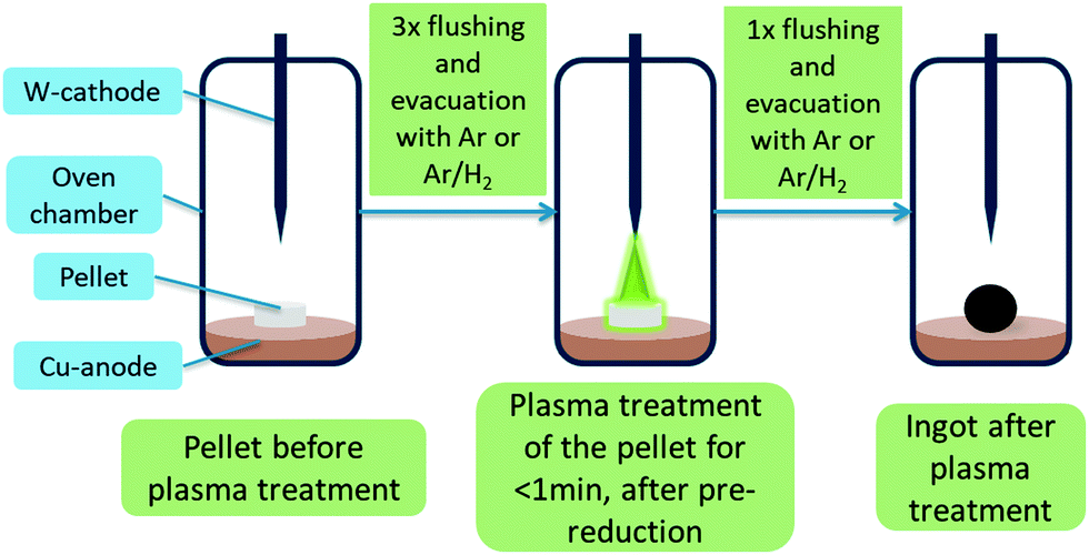 | ||
| Fig. 1 Illustrated treatment steps for plasma treatment of pellets inside the arc furnace. | ||
Most samples studied were treated as pellets. For this purpose, synthesized C12A7 was thoroughly mixed with different solid reductants, which are similar applied to getter materials, as listed in Table 1. The obtained mixtures were pressed with 10 t using a motorized pellet press resulting in pellets with a diameter of 13 mm and mass of about 0.5 g per pellet. Aluminum powder 99.5% metals basis by Alfa Aesar and graphite powder general purpose grade by Fischer Chemical were used as solid reductants. The pellets listed in Table 1 were treated until a homogeneous melting could be observed, which usually takes less than 1 min. At times, to obtain a homogeneous melt, the ingots needed to be flipped and treated on the bottom-side as well, as indicated in Table 1.
| Sample ID | Solid reductant | Atmosphere | I Plasma | Cycles |
|---|---|---|---|---|
| (a) C12A7 | None | Ar | 5 | 3x1x |
| (b) C12A7e− | None | 95% Ar/5% H2 | 5 | 6x0x |
| (c) C12A7e− (20 wt% Al) | 20 wt% Al | 95% Ar/5% H2 | 5 | 1x1x |
| (d) C12A7e− (3 wt% C) | 3 wt% graphite | 95% Ar/5% H2 | 5 | 3x0x |
| (e) C12A7e− (3 wt% C) | 3 wt% graphite | 95% Ar/5% H2 | 5 | 2x1x |
| (f) C12A7e− (5 wt% C) | 5 wt% graphite | 95% Ar/5% H2 | 5 | 1x1x |
| (g) C12A7e− (3 wt% C) | 3 wt% graphite | 95% Ar/5% H2 | 5 | 1x1x |
| (h) C12A7e− (3 wt% C) | 3 wt% graphite | 95% Ar/5% H2 | 5 | 1x0x |
Powders of C12A7 and mixtures with solid reductants without pressing were plasma treated by two methods (I) wrapping in graphite foil, (II) using a carbon crucible. For (I) samples were wrapped in 0.2 mm thick SIGRAFLEX® carbon foil pieces with a size of 2.5 cm × 4 cm. For (II) powders were filled in a custom-made graphite crucible with an inner diameter of 17 mm and inner height of 8 mm closed with a graphite lid allowing treatment of 0.5 g powder. Plasma intensity and treatment duration for achieving homogeneous products with both methods were estimated in initial tests, since visible control of the materials during plasma treatment is not possible. For both (I–II) the established “pre-reduction” step was done before samples were once treated with plasma intensity of 3 for 60 to 90 s followed by once flushing and evacuating the oven chamber with the process gas mixture before removing the sample.
Alternative to graphite as a carbon-based solid reductant, glucose was tested as carbon precursor, which is known as a sustainable carbon source from literature.51 5 g C12A7 were impregnated with 0.626 g (5 wt% C equivalent) or 1.389 g (10 wt% C equivalent) glucose in 75 mL H2O. During impregnation C12A7 was suspended in the solution in an ultrasonic bath. The suspensions were dried at 353 K for 1 h in a compartment dryer before the powder was carbonized under a nitrogen stream at 873 K for 1 h with a heating rate of 5 K min−1. C12A7 glucose-based solid reductants were treated as pellets. Besides Al, Ca was used as metallic solid reductant as described in the literature before.5 Ca or CaH2 were mixed with C12A7 inside an Ar filled glovebox before they were plasma treated in the graphite crucible. The mixture was directly filled into the crucible in the glove box while a short exposure to atmospheric conditions during the transfer of the crucible to the plasma oven was inevitable. Samples for alternative solid reductants experiments are summarized in Table 2.
| Sample ID | Solid reductant | Atmosphere | Container | Cycles |
|---|---|---|---|---|
| (i) | 5 wt% glucose | 95% Ar/5% H2 | Pellet | 3x1x |
| (j) | 10 wt% glucose | 95% Ar/5% H2 | Pellet | 6x0x |
| (k) | 5 wt% Ca | Ar | Crucible | 1x1x |
| (l) | 10 wt% Ca | Ar | Crucible | 1x1x |
| (n) | 10 wt% CaH2 | Ar | Crucible | 1x0x |
Ingots obtained after plasma treatment for samples listed in Table 1 were directly transferred into an Ar filled glovebox where they were ground in an agate mortar and stored under inert conditions. Samples from Table 2 were handled under atmospheric conditions, except samples with Ca as solid reductant that were directly transferred into the glovebox.
Characterization
EPR spectra were recorded using a MS 100 X-Band-EPR-Spectrometer by Magnettech. The spectra were recorded at room temperature with B0 = 340.0 mT, B0,sweep = 49.9 mT, sweep time tsweep = 500 s, 4096 steps, modulation amplitude MA = 0.1 mT, a microwave attenuation MWA = 10 dB and a microwave power MWP = 10 mW. The gain (GA) was fit for each sample. For the measurements the samples were filled into 50 μL Duran® glass micro pipettes by Hirschmann Laborgeräte GmbH, which were closed with clay. In order to compare the experiments, the measured first derivative of the spectra was integrated to obtain the absorption spectra. The absorption peak was then integrated with a linear background correction. To compare the obtained integrals, these were normalized using eqn (1), where IN is the normalized integral in arbitrary units (a.u.), IEPR the integral of the absorption peak in a.u, GA the gain, MA the modulation amplitude, MWP the microwave power and msample the sample mass. Additional ESR measurements were carried out using an X-band MiniScope MS5000 CW spectrometer (Freiberg Instruments) with a field homogeneity of ±5 μT within the sample region, 0.2 mT field modulation and 100 kHz modulation frequency. The samples were irradiated at 35 mW RF power and 9.47 GHz frequency acquiring 1 scan for 540 s at RT. The magnetic field B0 range was chosen 300–380 mT. The g-factors for the selected samples were determined using EasySpin 5.2.20.52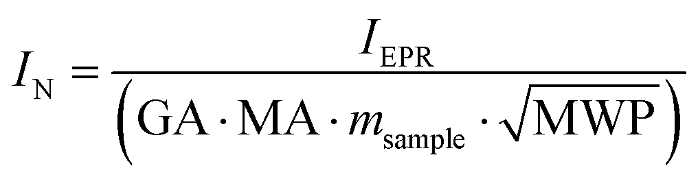 | (1) |
![[thin space (1/6-em)]](https://www.rsc.org/images/entities/char_2009.gif) :Cu-Kα2 = 2. The samples were prepared by thoroughly grinding the desired material in an agate mortar. The samples were measured on flat sample holders consisting of poly(methyl methacrylate). For standard qualitative measurements the diffraction pattern was measured in a range of 2θ = 10°–90° with a step size of 0.0205° and measuring time of 0.2 s step−1. For Rietveld refinements the measuring parameters were 2θ = 10°–140° with a step size of 0.005° and measuring time of 0.2 s step−1. PXRD data was analyzed using Match! – Version2 software by Crystal Impact GbR for quick qualitative phase analysis and FullProf53 software by J. Rodriguez-Carvajal for Rietveld refinements. CIF files for phase analysis and as starting models for Rietveld refinement were obtained from Crystallography Open Database (COD)54 or Inorganic Crystal Structure Database (ICSD).55 The composition of the samples was either determined by semi quantitative phase analysis using Match! – Version2 or as a result of Rietveld refinement using FullProf.
:Cu-Kα2 = 2. The samples were prepared by thoroughly grinding the desired material in an agate mortar. The samples were measured on flat sample holders consisting of poly(methyl methacrylate). For standard qualitative measurements the diffraction pattern was measured in a range of 2θ = 10°–90° with a step size of 0.0205° and measuring time of 0.2 s step−1. For Rietveld refinements the measuring parameters were 2θ = 10°–140° with a step size of 0.005° and measuring time of 0.2 s step−1. PXRD data was analyzed using Match! – Version2 software by Crystal Impact GbR for quick qualitative phase analysis and FullProf53 software by J. Rodriguez-Carvajal for Rietveld refinements. CIF files for phase analysis and as starting models for Rietveld refinement were obtained from Crystallography Open Database (COD)54 or Inorganic Crystal Structure Database (ICSD).55 The composition of the samples was either determined by semi quantitative phase analysis using Match! – Version2 or as a result of Rietveld refinement using FullProf.
For STA measurements a STA 449 F3 Jupiter® by NETZSCH was used, with a combination of differential scanning calorimetry (DSC) and thermogravimetric analysis (TG). The apparatus can be run using nitrogen or synthetic air up to 1573 K. The general heating rate was 10 K min−1. The samples were measured in corundum crucibles and typically about 10 mg sample were used. According to the literature42,46 oxygen oxidizes the mayenite-electride which leads to an uptake of oxygen and thus a mass gain. The theoretical mass gain from the electride with the maximum electron number to the stoichiometric oxygen-mayenite is 1.17 wt%. Due to this small value the sensitivity and error of the method were determined by multiple STA measurements under nitrogen and synthetic air for four different mayenite and mayenite-electride samples.
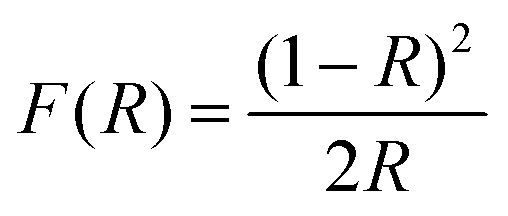
Diffuse reflectance UV-vis (DRUVVis) experiments were carried out using a PerkinElmer Lambda 950 spectrometer with an included 150 mm Ulbricht-sphere by Labsphere. The reference for the reflection measurement was a Spectralon® white standard by Labsphere. The spectra were recorded in a wavelength range from 200 to 2500 nm with an acquisition speed of 250 nm min−1, integration time of 0.2 s and data interval of 1 nm at room temperature. The reflection spectra were processed according to the literature5,42–44 with the Kubelka–Munk transformation using the following equation:
 | (2) |
 | (3) |
TEM measurements were carried out with a FEI Osiris TEM. The acceleration voltage was 200 kV. The samples were prepared by dispersing the sample with EtOH between two glass object slides. In this dispersion a graphite-covered Cu net was dipped, which is used as sample holder for the measurement.
Results and discussion
In the following discussion we first focus on the successful synthesis of C12A7e− by plasma treatment while discussing the influence of different solid reductants and treatment variations of powders. In the first subsection, we analyze in detail the properties of selected samples mainly focusing on their phase purity and the different synthetic procedures while discussing the electron concentration only qualitatively. Finally, in the second subsection, we critically discuss the suitability of some of the methods reported in the literature for the determination of a relevant property as the electron concentration for samples of our pellet-based synthesis approach. At the current state, we expect that the treatment of the precursors with the plasma is mainly a fast thermal process, as the precursors in case of the pellet route were treated until a homogeneous melting was observed and the foil or crucibles in case of the powder route were heated by the plasma.Plasma synthesized electrides
| [Ca24Al28O64]4+(O2−)2 + 2H2 ↔ [Ca24Al28O64]4+(e−)4 + 2H2O | (4) |
| 3[Ca24Al28O64]4+(O2−)2 + 4Al ↔ 3[Ca24Al28O64]4+(e−)4 + 2Al2O3 | (5) |
| [Ca24Al28O64]4+(O2−)2 + C ↔ [Ca24Al28O64]4+(e−)4 + CO2 | (6) |
| [Ca24Al28O64]4+(O2−)2 + 2Ca ↔ [Ca24Al28O64]4+(e−)4 + 2CaO | (7) |
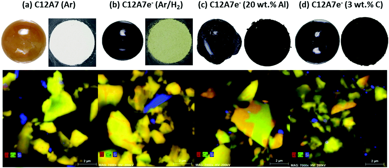 | ||
| Fig. 2 Top: Pictures of ingots obtained after plasma treatment and powders after grinding of the ingots; bottom: EDX maps of TEM studies of (a) pure C12A7 treated under Ar atmosphere, (b) pure C12A7 treated under 95% Ar/5% H2 atmosphere, (c) 20 wt%-Al/C12A7 mixture treated under 95% Ar/5% H2 and (d) 3 wt%-C/C12A7 mixture treated under 95% Ar/5% H2. The EDX images show the distribution of Al (red), Ca (green) and the ratio (yellow to orange) of both. Si (blue) is present due to TEM sample preparation. Orange areas are assigned to CA (krotite) secondary phase and yellow areas to C12A7 based on different Ca to Al ratios in the two phases. | ||
| Sample | (a) C12A7 | (b) C12A7e− (95% Ar/5% H2) | (c) C12A7e− (20 wt%-Al) | (d) C12A7e− (3 wt%-C) |
|---|---|---|---|---|
| Space group |
I![[4 with combining macron]](https://www.rsc.org/images/entities/char_0034_0304.gif) 3d (no. 220) 3d (no. 220) |
I3d (no. 220) |
I3d (no. 220) |
I3d (no. 220) |
| a/pm | 1199.75(3) | 1199.13(2) | 1199.942(19) | 1199.661(19) |
| R wp/% | 20.1 | 22.1 | 22.2 | 21.9 |
| R p/% | 15.2 | 16.6 | 16.6 | 15.8 |
| S/% | 1.4 | 1.4 | 1.5 | 1.5 |
| Phase fractions | ||||
| C12A7/wt% | 100 | 78.3(9) | 45.4(5) | 89.6(8) |
| CA/wt% | — | 5.6(4) | 55.6(7) | 10.4(4) |
| C5A3/wt% | — | 16.1(5) | — | — |
Addition of solid reductants like (c) Al or (d) C in form of graphite shows increases in electron concentration combined with a reduced number of required steps to reach higher electron concentrations visible through apparent color change. The addition of either solid reductants results in dark green/brown to black color of the ingots and the powders after grinding of the ingots as shown in Fig. 2, suggesting a higher electron concentration. Based on these results we can already infer that the plasma treatment of C12A7 mixtures in the presence of solid reductants enables the synthesis C12A7e− with high electron concentrations.
A major problem in using Al as solid reductant (c) is the resulting high amount of secondary phase leading to about 55 wt% CA secondary phase with only 45 wt% C12A7e− based on Rietveld refinement (the balance for refinement was only made for oxygen containing phases metallic Al visible as small grains attached to the ingots were not considered). The high amount of Al as solid reductant was necessary to obtain homogeneously colored black ingots and a resulting higher electron concentration. Preparation using only 5 or 10 wt% Al resulted in electride materials with a much brighter greenish color. The phase diagram of calcium aluminates can explain the strong formation of CA secondary phase with the higher Al2O3 content in the system formed during the reduction process as described by eqn (5).13
The use of carbon in form of powdered graphite as solid reductant (d) let to a product with a color in a similar range compared to Al addition. Advantageously, however, the amount of secondary CA phase was determined to be about only 10 wt%. As for an application in catalysis, high content of secondary phases may be critical, or lead to dubious conclusions, we consider this finding important. Secondary phase formation may be especially problematic if it takes place on the surface of the desired C12A7e− phase leading to decreased surface area and accessibility of the electride or may be coupled to secondary effects like decreased stability. Any physical separation of the primary and secondary phase appeared so far not possible for the obtained products. EDX mapping by TEM shows clear presence of the secondary CA phase (orange) together with C12A7 phase (yellow) in same particles forming common grain boundaries as shown in Fig. 2. The formation of the electride by addition of graphite as solid reductant presumably proceeds viaeqn (2) with the formation of CO2 or not shown in the equation formation of CO.
Based on these results we can conclude that the use of minor amounts (<5 wt%) of graphite addition is the most promising and favored way to obtain phase-pure mayenite electride materials with a high electron concentration by plasma treatment in a reducing atmosphere. Detailed characterization results to quantitatively determine the electron concentration are discussed in the Determination of electron concentration subsection. In general, the use of both solid reductants, aluminum and carbon, is practical, cheap and safe.
Treating pure C12A7 precursors wrapped in graphite foil resulted in dark ingots though powders after grinding only showed a bright greyish color. Therefore, it is not assumed that an mayenite material with electride properties could be successfully synthesized. PXRD analysis shows mainly presence of initial C12A7 phase, for some tests C5A3 or graphite from the foil attached to the ingots were observed as secondary phases. Ingots with attached graphite foil pieces were a general problem using graphite foil as reaction container and such pieces could in general not be removed manually from samples. Treatment of pure C12A7 in the graphite crucible showed no improvement in electron concentration based on visual observation and color inspection of the powders after grinding. Benefits using the graphite crucible were the avoidance of graphite foil pieces attached to the ingots, reduced secondary phase formation and a more controlled treatment possibility. Treatment of samples in foil often lead to holes burnt in the foil locally or non-heated parts of the precursor showing macroscopically heterogeneous product formation and unreacted precursor material after plasma treatment.
Wrapping the powders in graphite foil allowed testing Ca and CaH2 as solid reductants. Stable pellets could indeed not be obtained for mixtures containing Ca or CaH2 under the conditions applied for the pellet preparation of the other materials reported, as the pelletizing step required exposing the powder to air, which would cause Ca and CaH2 to react. Addition of Ca for the synthesis of C12A7e− with heating under vacuum is the most common method reported in the literature for metallic conducting electrides.12,13,25 Furthermore, carbon containers are thought to enhance electron concentration by acting as a further oxygen scavenger or a solid material acting as precursor for the creation of reductive atmospheres. Carbon crucibles have been reported in the literature for synthesis of C12A7e− though no plasma treatment of the crucible was done, they were solely used as containers/furnaces for heating.22,24 Based on our results we conclude that in our case the foil or crucible is also only acting as a container for the material, while the container is heated via the thermal plasma.
Using powder mixtures of C12A7 with either C, Ca or CaH2 solid reductants as precursors resulted in black ingots for both containers. Resulting powders showed light grey to dark green colors indicating electride formation. Compared with the dark brown to black color visible for pellet treatment of C12A7 graphite or aluminum mixtures no increased electron concentration was observed. Electride formation with Ca or CaH2 did not show an increased visible electron concentration based on the color compared to treatment of 3 wt%-C C12A7 pellets. PXRD for Ca and CaH2 prepared C12A7e− show formation of 10 to 14 and 35 wt% Al6Ca9O18 secondary phase, respectively.
Products mentioned in this section were generally only analyzed with PXRD for phase composition of crystalline phases and electron concentration are only judged based on visual impression by the apparent color of the material. Plasma treatment of powders was found to be possible in both containers while the carbon crucible allowed more reproducible results and a more controlled treatment. However, we found no advantage in terms of the general handling or increased electron concentration and reduced secondary phase amount compared to the primary pellet-based approach, even when highly reactive Ca and CaH2 were used as solid reductants.
Determination of electron concentration
In the following section, we discuss results for quantitative determination of the electron concentration of C12A7e−. In the literature several methods like DRUV/Vis spectroscopy, thermal analysis by TG, EPR spectroscopy, structural refinement of X-ray/neutron diffraction data, electric conductivity measurements, iodometry are employed for this purpose. We herein describe difficulties in applicability of used analytical methods and their uncertainties as this is scarcely reported. Results for thermal analysis, EPR spectroscopy and Rietveld refinement of PXRD data are discussed for different solid reductants, DRUV/Vis analysis was mainly focused on graphite as solid reductant, followed by comparison of obtained quantitative results for different methods.Fig. 3 shows results for DSC-TG experiments under synthetic air or N2 atmosphere for (a) Ar and (b) Ar/H2 plasma treated pure C12A7 and Ar/H2 plasma treated C12A7 with (c) 20 wt% Al or (d) 3 wt% C (graphite) solid reductant addition. For (a) C12A7 plasma treated in Ar atmosphere a residual mass uptake of 0.5 and 0.2 wt% from 623 K to 1573 K and a maximum mass uptake of 0.7 and 0.4 wt% from 623 K to 1273 K can be observed for N2 and synthetic air atmospheres respectively. The DSC curves for this sample show no clear signal. 95% Ar/5% H2 treated C12A7 (b) showed a maximum mass uptake of 0.5 and 0.7 wt% and a residual mass uptake of 0.3 and 0.5 wt% for N2 and synthetic air, respectively. Contrary to sample (a) an exothermic signal at about 700 K can be observed which is also reported by Trofymluk et al. and Matsuishi et al. which is correlated to oxidation of C12A7e− to C12A7 in literature.44,46
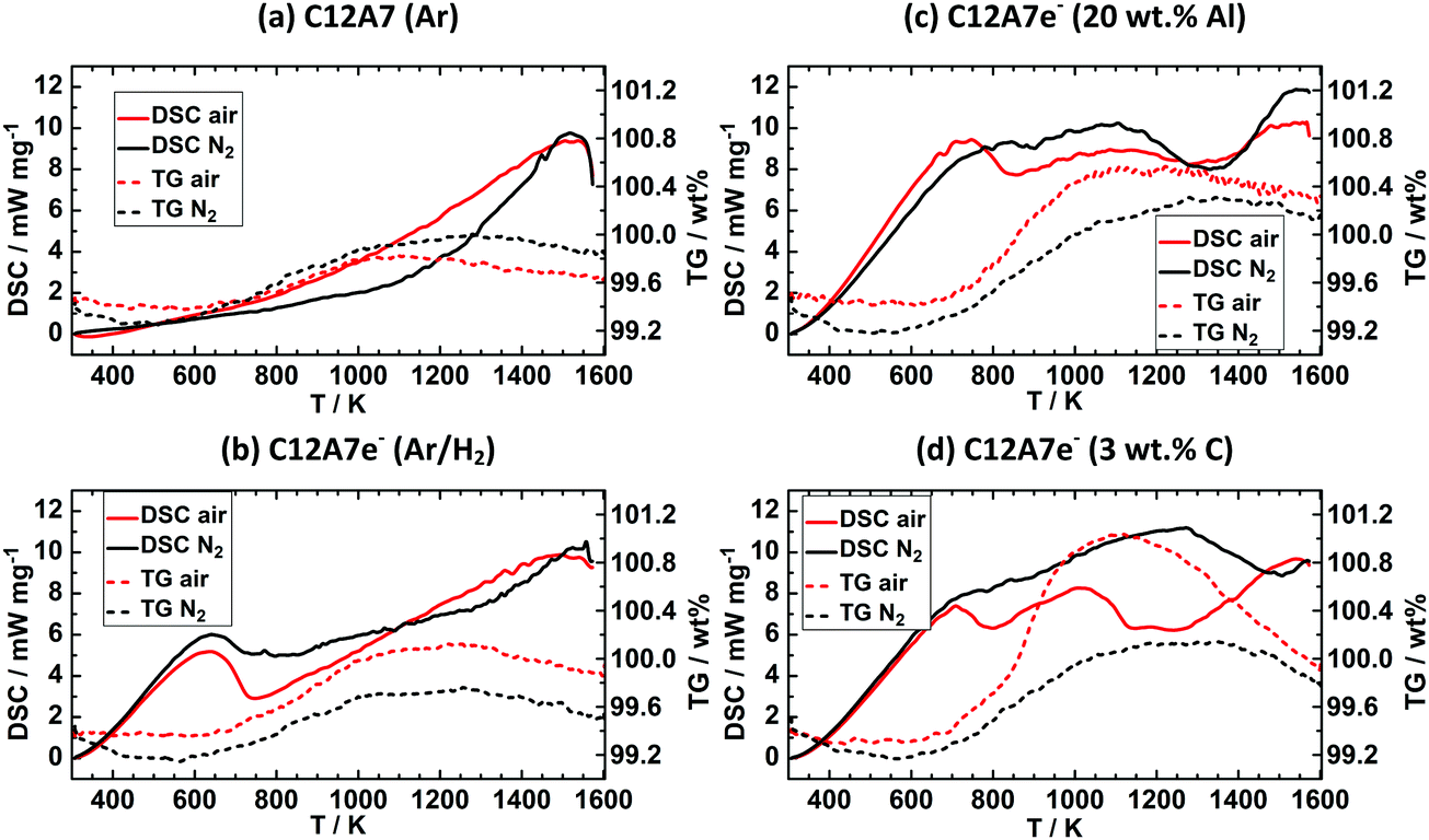 | ||
| Fig. 3 DSC-TG experiments of the powders obtained after plasma treatment, (a) C12A7 (Ar), (b) C12A7e− (95% Ar/5% H2), (c) C12A7e− (20 wt%-Al), (d) C12A7e− (3 wt%-C). Solid lines are respective DSC curves (exo. up) and dashed lines the TG curves. Black lines are experiments carried out under N2 atmosphere, while red lines belong to experiments with synthetic dry air. The stronger mass increase indicated by TG between 800 and 1300 K under synthetic air indicates the presence of electrides in (b–d). | ||
C12A7e− samples (c) and (d) based on solid reductant addition show residual mass uptakes of (c) 0.9 and 0.8 wt% and (d) 0.5 and 0.5 wt% with N2 and synthetic air respectively, while the maximum mass uptakes are (c) 1.0 and 1.1 wt% and (d) 0.9 and 1.7 wt% with N2 and synthetic air respectively. Both samples show two exothermic peaks with synthetic air at about 700 and 1200 K while under N2 for both samples no clear exothermic peak at 700 K is observed and only for (c) a peak at about 1300 K can be identified. The peak at 700 K well agrees with literature values while the second signal is not described in the literature and no direct identification of the origin is possible.44,46 Electron concentrations for all samples were calculated based on the residual mass uptake under synthetic air and are summarized in Table 4. The mass loss from the maximum mass at about 1050 to 1200 K to the residual mass at about 1650 K is described by Trofymluk et al. and Matsuishi et al. as an incorporation from oxygen species such as O− and (O2)−.44,46 However, we cannot explain the differences observed between N2 and synthetic air based on these assumptions. For pure N2 this mass uptake should not be observed. In reproducibility tests the same sample was tested four times under the respective conditions (N2 or synthetic air). The reproducibility tests indicated only an absolute accuracy of ±0.25 wt% in determination of the residual mass uptake. Based on this level of accuracy, in general electron concentrations based on TG experiments should be treated with care as the standard deviation corresponds already to an electron concentration of 0.5 × 1023 cm−3. This absolute value already corresponds to properties and electron concentration of a semiconducting electride characterized by a green color which is not the case for (a) showing a white color despite a calculated Ne value of 0.4 × 1023 cm−3 from TG analysis.
| Sample | N e/1021 cm−3 (thermal analysis) | N e/1021 cm−3 (DRUV/vis) | I N/a.u. (EPR) |
|---|---|---|---|
| (a) C12A7 (Ar) | 0.4 [0.2 wt%] | — | 0.7 |
| (b) C12A7e− (Ar/H2) | 1.0 [0.5 wt%] | — | 27.3 |
| (c) C12A7e− (20 wt% Al) | 1.5 [0.8 wt%] | — | 2500 |
| (d) C12A7e− (3 wt% C) | 1.1 [0.5 wt%] | 0.5 | 4630 |
| (e) C12A7e− (3 wt% C) | — | 1.2 | 4825 |
| (f) C12A7e− (5 wt% C) | — | 0.6 | 4018 |
| (g) C12A7e− (3 wt% C) | — | 0.3 | 2535 |
| (h) C12A7e− (3 wt% C) | — | 0.1 | 3458 |
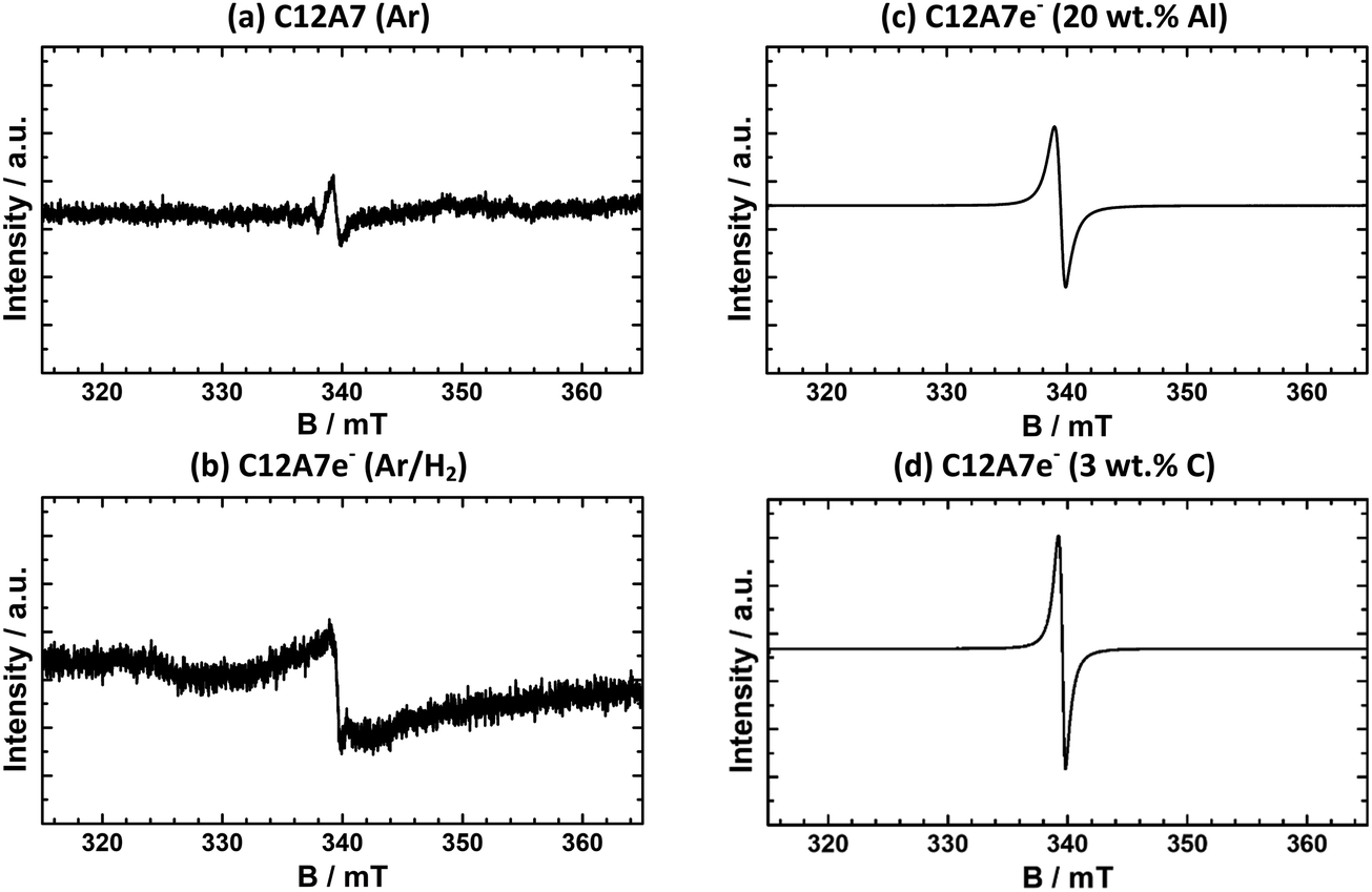 | ||
| Fig. 4 EPR spectra of powders after plasma treatment (a) C12A7 (Ar), (b) C12A7e− (95% Ar/5% H2), (c) C12A7e− (20 wt%-Al), (d) C12A7e− (3 wt%-C). For all samples, a signal appears at about 340 mT showing the presence of located electrons in the sample. Intensity scale is not the same for all samples, (a and b) are zoomed ∼5000 and ∼100 times, respectively. | ||
For a qualitative comparison of the EPR spectra, normalized intensities IN of peaks of integrated first derivative spectra were determined by integration of the peak area and normalization with eqn (1). The graphite-based electride sample shown (d) has an IN = 4630 and the aluminum-based (c) of IN = 2500. For all synthesized graphite-based C12A7e− samples by the same synthesis method, values for the normalized intensity range from IN = 2540 to 4800. Nevertheless, EPR analysis of samples clearly confirms the presence of C12A7e− by g-factor analysis and comparison with literature results. Furthermore, the IN as listed in Table 4 show a clear correlation of the electron concentration in comparison of samples (a) to (d). From these results, we can conclude that in order to achieve a high electron concentration, the use of gaseous reductants (95% Ar/5% H2) is insufficient and solid reductants are required. A comparison of the results for electron concentration determination by EPR with the other applied methods is done in Section 3.2.5.
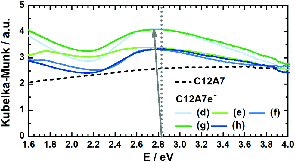 | ||
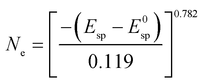
| Fig. 5 Kubelka–Munk transformed DRUV-vis spectra for several graphite-based C12A7e− sample batches (solid) and carbonized C12A7 precursor sample (dashed) for comparison. According to Matsuishi et al., the dotted line at 2.83 eV corresponds to the absorption peak maximum for an electron concentration of Ne = 1 × 1018 cm−3.5 With increasing Ne the maximum shifts towards lower energy values, as illustrated with the arrow, which can be used for estimating Ne. | ||
In Table 4 electron concentrations obtained from DRUV/Vis for different solid reductants and different graphite-based sample batches are summarized together with measures from other methods. All graphite-based samples in Fig. 5 were synthesized by plasma treatment under 95% Ar/5% H2 atmosphere until homogeneous melting balls were observed. The resulting powders all displayed similar appearance in color after grinding. For the determination of the electron concentration with eqn (3) the position of the maximum peak was determined (in order to do so this was done by first smoothing the data with FFT filter and second formation of the first derivative to determine the maximum). Smoothing of the data was done as the noise level of the spectra led to erratic determination of the maximum position, i.e. values with higher electron concentrations than stoichiometrically possible were observed. The error based on the accuracy of the DRUVVis measurement in determining the maximum position is estimated as ±0.02 eV. This systematic accuracy results in a high relative error in the determination of the respective electron concentration, e.g. sample (d) has an electron concentration of Ne = 0.5 × 1021 cm−3 with the error of ±0.02 eV the calculated maximum and minimum values are Ne = 0.3 × 1021 cm−3 and Ne = 0.6 × 1021 cm−3 which corresponds to a relative error of roughly 50%. Our suggestion is that in respect of this high uncertainty values should be rather discussed qualitatively. An indication of the conductivity properties of C12A7e−, i.e. insulator, semi-conductor or conductor is possible with literature data. In comparison with studies by the group of Hosono, we conclude that all 3 wt% graphite-based C12A7e− are semiconductors with properties close to metallic conductors.5,42–44 However, the results obtained by the method of DRUVVis itself should be discussed with caution, as eqn (3) in combination with the method-inherent relative error based on experimental data can lead to difficulties in highly accurate quantitative determination of the electron concentration.
 | ||
| Fig. 6 Rietveld refinement of PXRDs of powders after plasma treatment, (a) C12A7 (Ar); (b) C12A7e− (95% Ar/5% H2); (c) C12A7e− (20 wt%-Al); (d) C12A7e− (3 wt%-C). PXRD were measured with λ1 = 154.06 pm, λ2 = 154.44 pm, λ1/λ2 = 2. Parameters obtained from Rietveld refinement are listed in Table 3. First row of Bragg markers corresponds to C12A7e−, second row to CA and third row to C5A3 phases. | ||
Lattice parameters obtained from Rietveld refinement together with phase fractions are summarized in Table 3. In studies by Palacios et al. and Kanbara et al. an increase of the lattice parameter a for increased electron concentrations is reported.10,29,40 Palacios et al. reported an increase from 1197.113(8) pm to 1199.580(7) pm and 1198.215(9) pm to 1199.522(2) pm from C12A7 to black C12A7e−.10,40 Kanbara et al. reported an increase from 1198.6 pm for C12A7 to 1199.9 pm.29 From our results we cannot confirm this behavior. a of pure (a) C12A7 treated in Ar is about 1 pm larger than the literature values. This increase might be caused due to the rapid heating and cooling during the plasma synthesis or the expected structural distortion compared to the electride structure caused by the occupancy of two cages by O2− for C12A7 instead of four cages by e− for C12A7e−.13 Though comparing (b) C12A7e− treated in 95% Ar/5% H2 atmosphere with solid reductant synthesized (c and d) C12A7e− we do see an increase of a from 1199.13(2) pm to (c) 1199.942(19) pm or (d) 1199.661(19) pm showing the identical behavior for a as reported in the literature for an increasing electron concentration. However, we cannot exactly explain why the values of a for the samples (b) and (d) are significantly smaller compared to sample (a). As the complete refinement also for atomic parameters was not possible and the lattice parameters do not completely follow the literature reported trends, we believe it is fair to conclude that it is doubtful whether Rietveld refinement of powder diffraction data obtained on standard diffraction instruments is suitable to analyze the electron concentration in mayenite electrides; however the situation concerning data quality may become different when using synchrotron beamline derived PXRD data. We have reason to believe that the complexity of the structure, especially of the mixed occupancy of the cage anion position, may make additional studies of the materials by single crystal XRD for refinement of atomic positions necessary.
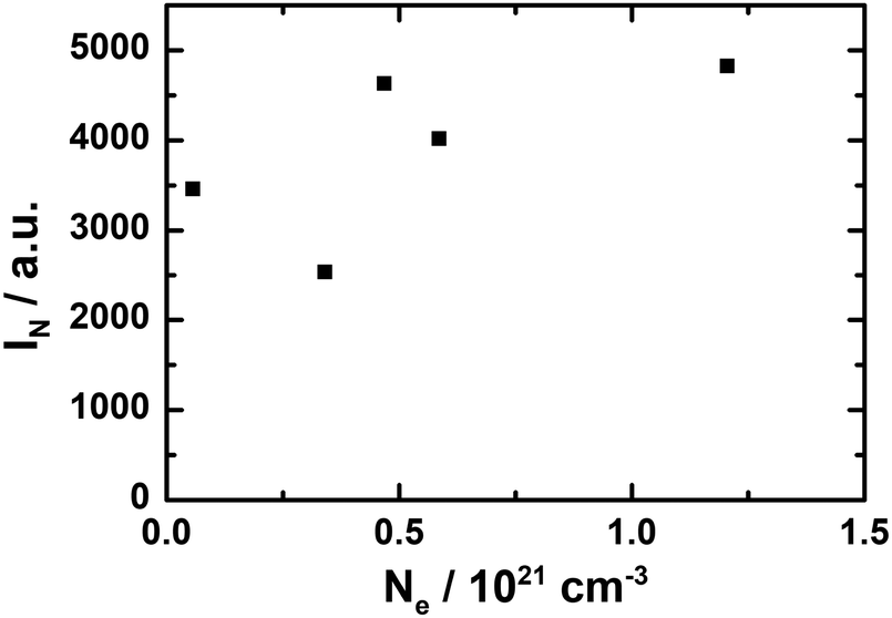 | ||
| Fig. 7 Correlation analysis for electron concentration Ne values determined by DRUV/vis analysis and corresponding normalized IN of the absorption EPR spectra. A linear relationship as expected cannot be seen reliably between Ne and IN. | ||
Conclusions
In the present work we report a new, scalable and facile method to synthesize mayenite-based electrides (C12A7e−). Plasma treatment of mixtures of mayenite with aluminum or graphite as solid reductants, which are similar applied to getter materials, in Ar or Ar/H2 atmosphere lead to the formation of mayenite based electrides. The solid reductant has a major influence on the structural composition of the product composite: aluminum leads to enhanced formation of krotite as a secondary phase, which can be prevented by using graphite as reductant. Thus, using a plasma treatment of a C12A7/graphite mixture was found as the optimum to achieve high electron concentrations while achieving a tolerable secondary phase amount. The analysis of the electron concentration was achieved by EPR-, DRUV/vis spectroscopy, Rietveld refinement of PXRD and DSC-TG under oxidizing atmospheres. However, in a critical revision we found that data obtained from these methods must be taken with caution and may in certain cases, especially if only a single analytical method is employed, be limited to obtaining only qualitative information about the electron concentration in mayenite electrides. Furthermore, preparation of multiple samples might be required to obtain statistical meaningful characterization results for the electron concentration. Based on our characterization results and in comparison with the relevant literature we conclude that the plasma-based approach provides a suitable synthesis of semiconducting close to metallic conducting electride materials. Furthermore, plasma treatment in reductive atmospheres, i.e. 95% Ar/5% H2 appears to be insufficient to obtain high electron concentrations. In this case, the use of solid reductants is recommended for the latter purpose. With the presented scalable plasma-based preparation method, mayenite and related electrides may find a broader range of applications in heterogeneous catalysis.Author contributions
Conceptualization, S. W., S. S., M. S., S. A. S.; data curation, S. W., K. S., S. A. S.; formal analysis, S. W.; funding acquisition, S. A. S.; investigation, S. W., S. S., M. S., K. S.; methodology, S. W., S. S., M. S., K. S., S. A. S.; project administration, S. W., S. S., M. S., S. A. S.; resources, S. A. S.; supervision, S. S., M. S., H. K., R. G., S. A. S.; validation, S. W., S. S., M. S., K. S., H. K., R. G., S. A. S.; visualization, S. W.; writing—original draft preparation, S. W.; writing—review and editing, S. W., S. A. S., M. S., K. S., H. K., R. G., S. A. S.Conflicts of interest
There are no conflicts to declare.Acknowledgements
Thanks to Stephan Arnold, Tamara Gabriel and Sertac Altay (all hte GmbH, Heidelberg) for support in measuring PXRDs. Thanks to Dr Armin Bader and Ulrich Flörchinger (all BASF SE, Ludwigshafen) for supporting with DRUV/Vis-spectroscopy and TEM measurements, respectively. Thanks to Nicolai Rosenbaum (KIT, student internship at BASF) for supporting the initial EPR measurements on MS100. Thanks to Jamal N. M. Aman and Prof. Jörn Schmedt auf der Günne (both University of Siegen) for help and conceptual discussion of EPR experiments. Thanks to Mert Özen, Enrico Urbano and Andreas Kugler (all hte GmbH, Heidelberg) for initial studies on the plasma synthesis. Funding by BASF SE is gratefully acknowledged.Notes and references
- A. Ellaboudy, J. L. Dye and P. B. Smith, Cesium 18-crown-6 compounds. A crystalline ceside and a crystalline electride, J. Am. Chem. Soc., 1983, 105, 6490–6491 CrossRef CAS.
- S. B. Dawes, D. L. Ward, R. H. Huang and J. L. Dye, First electride crystal structure, J. Am. Chem. Soc., 1986, 108, 3534–3535 CrossRef CAS.
- J. L. Dye, Electrides: early examples of quantum confinement, Acc. Chem. Res., 2009, 42, 1564–1572 CrossRef CAS PubMed.
- K. Hayashi, S. Matsuishi, T. Kamiya, M. Hirano and H. Hosono, Light-induced conversion of an insulating refractory oxide into a persistent electronic conductor, Nature, 2002, 419, 462–465 CrossRef CAS PubMed.
- S. Matsuishi, Y. Toda, M. Miyakawa, K. Hayashi, T. Kamiya, M. Hirano, I. Tanaka and H. Hosono, High-density electron anions in a nanoporous single crystal: Ca24Al28O644+(4e−), Science, 2003, 301, 626–629 CrossRef CAS PubMed.
- S. W. Kim and H. Hosono, Synthesis and properties of 12CaO·7Al2O3 electride: review of single crystal and thin film growth, Philos. Mag., 2012, 92, 2596–2628 CrossRef CAS.
- H. B. Bartl and T. Scheller, On the Structure of 12CaO·7Al2O3, Neues Jahrb. Mineral., Monatsh., 1970, 35, 547–552 Search PubMed.
- H. Hosono and Y. Abe, Occurrence of superoxide radical ion in crystalline calcium aluminate 12CaO·7Al2O3 prepared via solid-state reactions, Inorg. Chem., 1987, 26, 1192–1195 CrossRef CAS.
- J. Jeevaratnam, L. S. Dent Glasser and F. P. Glasser, Structure of Calcium Aluminate, 12CaO·7Al2O3, Nature, 1962, 194, 764–765 CrossRef CAS.
- L. Palacios, A. G. de La Torre, S. Bruque, J. L. García-Muñoz, S. García-Granda, D. Sheptyakov and M. A. G. Aranda, Crystal structures and in-situ formation study of mayenite electrides, Inorg. Chem., 2007, 46, 4167–4176 CrossRef CAS PubMed.
- H. Boysen, M. Lerch, A. Stys and A. Senyshyn, Structure and oxygen mobility in mayenite (Ca12Al14O33): a high-temperature neutron powder diffraction study, Acta Crystallogr., Sect. B: Struct. Sci., Cryst. Eng. Mater., 2007, 63, 675–682 CrossRef CAS PubMed.
- S.-W. Kim, S. Matsuishi, M. Miyakawa, K. Hayashi, M. Hirano and H. Hosono, Fabrication of room temperature-stable 12CaO·7Al2O3 electride: a review, J. Mater. Sci.: Mater. Electron., 2007, 18, 5–14 CrossRef.
- J. R. Salasin and C. Rawn, Structure Property Relationships and Cationic Doping in [Ca24Al28O64]4+ Framework: A Review, Crystals, 2017, 7, 143 CrossRef.
- J. A. Imlach, L. S. Dent Glasser and F. P. Glasser, Excess oxygen and the stability of “12CaO·7Al2O3”, Cem. Concr. Res., 1971, 1, 57–61 CrossRef CAS.
- S. Yang, J. N. Kondo, K. Hayashi, M. Hirano, K. Domen and H. Hosono, Formation and Desorption of Oxygen Species in Nanoporous Crystal 12CaO·7Al2O3, Chem. Mater., 2004, 16, 104–110 CrossRef CAS.
- K. Hayashi, M. Hirano, Q.-X. Li, M. Nishioka, M. Sadakata, Y. Torimoto, S. Matsuishi and H. Hosono, Electric Field Emission of High Density O− Ions from 12CaO·7Al2O3 Engineered to Incorporate Oxygen Radicals, Inorg. Chem., 2002, 5, J13 CAS.
- K. Hayashi, Heavy doping of H− ion in 12CaO·7Al2O3, J. Solid State Chem., 2011, 184, 1428–1432 CrossRef CAS.
- J. M. Polfus, K. Toyoura, C. H. Hervoches, M. F. Sunding, I. Tanaka and R. Haugsrud, Nitrogen and hydrogen defect equilibria in Ca12Al14O33: a combined experimental and computational study, J. Mater. Chem., 2012, 22, 15828 RSC.
- H. Boysen, I. Kaiser-Bischhoff and M. Lerch, Anion Diffusion Processes in O- and N-Mayenite Investigated by Neutron Powder Diffraction, Diffus. Fundam., 2008, 8, 2.1–2.8 Search PubMed.
- F. Hayashi, Y. Tomota, M. Kitano, Y. Toda, T. Yokoyama and H. Hosono, NH(2−) dianion entrapped in a nanoporous 12CaO·7Al2O3 crystal by ammonothermal treatment: reaction pathways, dynamics, and chemical stability, J. Am. Chem. Soc., 2014, 136, 11698–11706 CrossRef CAS PubMed.
- S. Kim, M. Miyakawa, K. Hayashi, T. Sakai, M. Hirano and H. Hosono, Simple and efficient fabrication of room temperature stable electride: melt-solidification and glass ceramics, J. Am. Chem. Soc., 2005, 127, 1370–1371 CrossRef CAS PubMed.
- J. H. Chung, J. H. Ryu, J. W. Eun, B. G. Choi and K. B. Shim, One-Step Synthesis of a 12CaO·7Al2O3 Electride via the Spark Plasma Sintering (SPS) Method, Electrochem. Solid-State Lett., 2011, 14, E41 CrossRef CAS.
- A. M. Volodin, V. I. Zaikovskii, R. M. Kenzhin, A. F. Bedilo, I. V. Mishakov and A. A. Vedyagin, Synthesis of nanocrystalline calcium aluminate C12A7 under carbon nanoreactor conditions, Mater. Lett., 2017, 189, 210–212 CrossRef CAS.
- D. Jiang, Z. Zhao, S. Mu, V. Phaneuf and J. Tong, Simple and Efficient Fabrication of Mayenite Electrides from a Solution-Derived Precursor, Inorg. Chem., 2017, 56, 11702–11709 CrossRef CAS PubMed.
- K. Khan, A. K. Tareen, M. Aslam, K. H. Thebo, U. Khan, R. Wang, S. S. Shams, Z. Han and Z. Ouyang, A comprehensive review on synthesis of pristine and doped inorganic room temperature stable mayenite electride, [Ca24Al28O64]4+(e−)4 and its applications as a catalyst, Prog. Solid State Chem., 2019, 54, 1–19 CrossRef CAS.
- Y. Toda, H. Yanagi, E. Ikenaga, J. J. Kim, M. Kobata, S. Ueda, T. Kamiya, M. Hirano, K. Kobayashi and H. Hosono, Work Function of a Room-Temperature, Stable Electride [Ca24Al28O64]4+(e−)4, Adv. Mater., 2007, 19, 3564–3569 CrossRef CAS.
- M. Kitano, Y. Inoue, Y. Yamazaki, F. Hayashi, S. Kanbara, S. Matsuishi, T. Yokoyama, S.-W. Kim, M. Hara and H. Hosono, Ammonia synthesis using a stable electride as an electron donor and reversible hydrogen store, Nat. Chem., 2012, 4, 934–940 CrossRef CAS PubMed.
- M. Kitano, S. Kanbara, Y. Inoue, N. Kuganathan, P. V. Sushko, T. Yokoyama, M. Hara and H. Hosono, Electride support boosts nitrogen dissociation over ruthenium catalyst and shifts the bottleneck in ammonia synthesis, Nat. Commun., 2015, 6, 6731 CrossRef CAS PubMed.
- S. Kanbara, M. Kitano, Y. Inoue, T. Yokoyama, M. Hara and H. Hosono, Mechanism Switching of Ammonia Synthesis Over Ru-Loaded Electride Catalyst at Metal-Insulator Transition, J. Am. Chem. Soc., 2015, 137, 14517–14524 CrossRef CAS PubMed.
- M. Hara, M. Kitano and H. Hosono, Ru-Loaded C12A7:e− Electride as a Catalyst for Ammonia Synthesis, ACS Catal., 2017, 7, 2313–2324 CrossRef CAS.
- S.-W. Kim, K. Hayashi, M. Hirano, H. Hosono and I. Tanaka, Electron Carrier Generation in a Refractory Oxide 12CaO·7Al2O3 by Heating in Reducing Atmosphere: Conversion from an Insulator to a Persistent Conductor, J. Am. Ceram. Soc., 2006, 89, 3294–3298 CrossRef CAS.
- S. W. Kim, S. Matsuishi, T. Nomura, Y. Kubota, M. Takata, K. Hayashi, T. Kamiya, M. Hirano and H. Hosono, Metallic state in a lime-alumina compound with nanoporous structure, Nano Lett., 2007, 7, 1138–1143 CrossRef CAS PubMed.
- K. Khan, A. K. Tareen, S. Elshahat, N. Muhammad, J. Li, I. Aboodd, L. Bibbò, A. Yadav, R. U. Rehman Sagar, U. Khan and Z. Ouyang, Facile metal-free reduction-based synthesis of pristine and cation-doped conductive mayenite, RSC Adv., 2018, 8, 24276–24285 RSC.
- K. Khan, A. Khan Tareen, S. Elshahat, A. Yadav, U. Khan, M. Yang, L. Bibbò and Z. Ouyang, Facile synthesis of a cationic-doped Ca24Al28O644+(4e−) composite via a rapid citrate sol-gel method, Dalton Trans., 2018, 47, 3819–3830 RSC.
- F. Li, X. Zhang, H. Liu, J. Zhao, Y. Xiao, Q. Feng and J. Zhang, Rapid synthesis of inorganic [Ca24Al28O64]4+(e−)4 electride and its performance as an electron thermal emitter, Vacuum, 2018, 158, 152–157 CrossRef CAS.
- F. Li, X. Zhang and J. Zhang, Aluminothermic synthesis of [Ca24Al28O64]4+(4e−) electride ceramic directly from Ca3Al2O6 precursor, Vacuum, 2019, 167, 352–356 CrossRef CAS.
- F. Li, X. Zhang and H. Liu, Insights into the direct formation of [Ca24Al28O64]4+(4e−) and its electrical characterization, J. Am. Ceram. Soc., 2020, 103, 35–42 CrossRef CAS.
- J. R. Salasin, S. E. A. Schwerzler, R. Mukherjee, D. J. Keffer, K. E. Sickafus and C. J. Rawn, Direct Formation and Structural Characterization of Electride C12A7, Materials, 2019, 12, 84 CrossRef CAS PubMed.
- D. Jiang, Z. Zhao, S. Mu, H. Qian and J. Tong, Facile and Massive Aluminothermic Synthesis of Mayenite Electrides from Cost-Effective Oxide and Metal Precursors, Inorg. Chem., 2019, 58, 960–967 CrossRef CAS PubMed.
- L. Palacios, A. Cabeza, S. Bruque, S. García-Granda and M. A. G. Aranda, Structure and electrons in mayenite electrides, Inorg. Chem., 2008, 47, 2661–2667 CrossRef CAS PubMed.
- T. Sakakura, K. Tanaka, Y. Takenaka, S. Matsuishi, H. Hosono and S. Kishimoto, Determination of the local structure of a cage with an oxygen ion in Ca12Al14O33, Acta Crystallogr., Sect. B: Struct. Sci., Cryst. Eng. Mater., 2011, 67, 193–204 CrossRef CAS PubMed.
- S. Matsuishi, T. Nomura, M. Hirano, K. Kodama, S.-i. Shamoto and H. Hosono, Direct Synthesis of Powdery Inorganic Electride [Ca24Al28O64]4+(e−)4 and Determination of Oxygen Stoichiometry, Chem. Mater., 2009, 21, 2589–2591 CrossRef CAS.
- S. W. Kim, T. Shimoyama and H. Hosono, Solvated electrons in high-temperature melts and glasses of the room-temperature stable electride Ca24Al28O644+·4e−, Science, 2011, 333, 71–74 CrossRef CAS PubMed.
- S. Matsuishi, S. W. Kim, T. Kamiya, M. Hirano and H. Hosono, Localized and Delocalized Electrons in Room-Temperature Stable Electride [Ca24Al28O64]4+(O2−)2-x(e−)2x: Analysis of Optical Reflectance Spectra, J. Phys. Chem. C, 2008, 112, 4753–4760 CrossRef CAS.
- T. Yoshizumi, S. Matsuishi, S.-W. Kim, H. Hosono and K. Hayashi, Iodometric Determination of Electrons Incorporated into Cages in 12CaO·7Al2O3 Crystals, J. Phys. Chem. C, 2010, 114, 15354–15357 CrossRef CAS.
- O. Trofymluk, Y. Toda, H. Hosono and A. Navrotsky, Energetics of Formation and Oxidation of Microporous Calcium Aluminates: A New Class of Electrides and Ionic Conductors, Chem. Mater., 2005, 17, 5574–5579 CrossRef CAS.
- S. W. Kim, M. Miyakawa, M. Hirano, Y. Kohama, H. Kawaji, T. Atake, H. Ikegami, K. Kono and H. Hosono, Superconducting Transition in Electron-Doped 12CaO·7Al2O3, Mater. Trans., 2008, 49, 1748–1752 CrossRef CAS.
- D. Vollath, Plasma synthesis of nanopowders, J. Nanopart. Res., 2008, 10, 39–57 CrossRef CAS.
- G. Kolios, T. Mattke, J. M. Mormul, A. N. Parvulescu, F. Rosowski, S. Schäfer and S. A. Schunk, Composite material comprising an electride compound, WO002018189216A1, 2018 Search PubMed.
- G. Kolios, T. Mattke, J. M. Mormul, A. N. Parvulescu, F. Rosowski, S. Schäfer and S. A. Schunk, Process for preparing an electride compound, WO002018189218A1, 2018 Search PubMed.
- M.-M. Titirici and M. Antonietti, Chemistry and materials options of sustainable carbon materials made by hydrothermal carbonization, Chem. Soc. Rev., 2010, 39, 103–116 RSC.
- S. Stoll and A. Schweiger, EasySpin, a comprehensive software package for spectral simulation and analysis in EPR, J. Magn. Reson., 2006, 178, 42–55 CrossRef CAS PubMed.
- J. Rodríguez-Carvajal, Recent advances in magnetic structure determination by neutron powder diffraction, Physica B, 1993, 192, 55–69 CrossRef.
- S. Gražulis, D. Chateigner, R. T. Downs, A. F. T. Yokochi, M. Quirós, L. Lutterotti, E. Manakova, J. Butkus, P. Moeck and A. Le, Bail, Crystallography Open Database - an open-access collection of crystal structures, J. Appl. Crystallogr., 2009, 42, 726–729 CrossRef PubMed.
- F. H. Allen, The Development, Status and Scientific Impact of Crystallographic Databases, Acta Crystallogr., Sect. A: Found. Crystallogr., 1998, 54, 758–771 CrossRef.
Footnotes |
| † Dedicated to Ferdi Schüth on the occasion of his 60th birthday. |
| ‡ Electronic supplementary information (ESI) available. See DOI: 10.1039/d0qm00688b |
| § Current address: Institute for Chemical Technology and Polymer Chemistry (ITCP); Institute of Catalysis Research and Technology (IKFT), Karlsruhe Institute of Technology (KIT), Engesserstraße 20, 76131 Karlsruhe, Germany. e-mail: sebastian.weber@kit.edu |
| This journal is © the Partner Organisations 2021 |