
 Open Access Article
 This Open Access Article is licensed under a Creative Commons Attribution-Non Commercial 3.0 Unported Licence
Advances in the preparation and biological applications of core@shell nanocrystals based on quantum dots and noble metal
Xi Wanga,
Peng Wangc,
Meng Li *b and
Jian Li*a
*b and
Jian Li*a
aCentral Hospital Affiliated to Shandong First Medical University, Jinan, Shandong 250013, China. E-mail: zxyyjzlj@163.com
bInstitute of Resource and Environmental Innovation, School of Municipal and Environmental Engineering, Shandong Jianzhu University, Jinan 250101, China. E-mail: mengli_ujn@163.com
cDepartment of Public Scientific Research Platform, School of Clinical and Basic Medicine, Shandong First Medical University, Shandong Academy of Medical Sciences, Jinan, China
First published on 20th August 2024
Abstract
Core/shell structured nanoparticles (NPs) are a novel category of functional materials that have garnered widespread attention due to their advantageous preparation methods, unique characteristics, and multifunctional application prospects, which have shown significant performance in materials chemistry and many other fields, such as electronics, biomedical, pharmaceutical, optics, and catalysis. Although some reviews about core/shell NPs have been published, there is still an intense requirement for an extensive review about the updated literature and new reported core/shell nanomaterials. Colloidal quantum dots (QDs) and noble metal NPs have a very small size, which results in the large surface-to-volume ratio and under-coordinated chemical bonds. As a result, the effort on the design of core–shell structure has been essential for colloidal QDs and noble metal NPs. In this review, the core–shell structures dominated by traditional QDs and CsPbX3 perovskite QDs, as well as noble metal nanocrystals (NCs) were summarized. The applications of the above core–shell structure NCs in medical or biological fields such as sensing, biological imaging, medical diagnostics and therapeutics, immunological diagnosis were discussed. The main objective of this review is to provide a better basis for the synthesis, properties, and biomedical applications of QDs or noble metal core/shell NPs, which is beneficial for the further development of QDs, noble metal NPs, and other NPs.
1. Introduction
Coating bare core nanoparticles (NPs) enhances the dispersion and stability of the core particles, while also altering or enhancing their original properties. Due to the external coating, the optical activity and photooxidation stability are significantly improved. This presents a promising opportunity to explore the potential applications of nanomaterials in various domains.1 The nature of core–shell structured quantum dots (QDs) is not a simple summation of shells, but rather a creative modification of these discrete systems, resulting in a wide range of performance enhancements in areas such as catalysis, labelling, optoelectronic devices, pharmaceuticals and biology. Novel constructive assemblies related to core–shell structured QDs can be made from a combination of several materials, such as carbon ribbons, carbon nanotubes, and metal or metal oxide NPs, and these designs can open up a new dimension of research in multidisciplinary science. The core–shell structured QDs are a key factor in solving the challenges encountered in the development of energy storage devices and alternative power sources. Core/shell NPs have exhibited attractive performance in many applications such as biomedicine,2,3 catalysis,4 electronics,5 enhancing photoluminescence (PL), creating photonic crystals,6 and so on. Especially in the biomedical field, the majority of these particles are used for bioimaging,7 controlled drug release, targeted drug delivery,7–9 cell labelling,7,10 tissue engineering applications.11,12Although some reviews about core/shell NPs have been published, an extensive review with updated literature on core/shell NPs is still desired. Among the reported nanomaterials, colloidal QDs and noble metal NPs have a very small size (generally <10 nm), which results in a large surface-to-volume ratio and under-coordinated chemical bonds. Surface atoms have high chemical reactivity to oxidation or adsorption of other foreign atoms, ionic migration and trapping of charge carriers, which have obviously influence on the chemical and physical properties of the NPs. As a result, the effort on the design of the core–shell structure was essential for colloidal QDs and noble metal NPs. The most common application of core/shell NPs were optoelectronics, catalysis, optical bioimaging, biological labelling. All of these applications mainly relied on the small-sized NPs, especially noble metals and QDs. Different to the previous reviews on core–shell structures, we mainly summarized the core–shell structures dominated by QDs and noble metal NCs.
QDs have garnered increasing attention from researchers. Among these materials, II–VI semiconductors such as ZnO, ZnS, CdTe, and CdS have demonstrated stable chemical and optoelectronic properties. These materials can be combined with noble metals and other substances to create various core/shell structure morphologies, which can serve as both the core and the shell. The design and production of these materials have the potential to open up new avenues of research in multidisciplinary science. These properties make them highly valuable in various fields, including light-emitting diodes (LEDs), solar cells, sensors, detectors, and catalysts. The preparation processes for these materials have become more elaborate due to advancements in nanotechnology.1,13 When two II–VI semiconductor materials are combined to form a heterostructure, their properties can be significantly enhanced compared to a single crystal. Recent years, lead halide perovskites not only showed great application potential in photovoltaic and other optoelectronic device applications, but also performed good applications in energy conversion and biomedical directions due to their attractive properties. However, the poor stability of lead halide perovskites NCs severely limits its application research.14–19 Preparation of robust shell encapsulation to cover CsPbX3 core is important for improving the stability of lead halide perovskites.
Noble metals such as gold (Au), silver (Ag), palladium (Pd), platinum (Pt), osmium (Os), iridium (Ir), ruthenium (Ru), and rhodium (Rh) possess excellent chemical stability, corrosion resistance, electrical conductivity, ductility, and catalytic properties. Single semiconductor materials have limited catalytic ability and uncontrollable selectivity of products. However, by loading noble metal NPs onto the surface of semiconductor materials, the catalytic efficiency and selectivity of products can be effectively improved. This is because the electrons and holes generated after illumination are separated on the noble metal and semiconductor, respectively. Subsequently, chemical reactions occur in different locations, effectively preventing the recombination of electrons and holes and enhancing catalytic efficiency. Additionally, the noble metal that is loaded can also modify the catalytic products. For example, when Pt-loaded TiO2 NPs are used, the decomposition of propyne under light can occur. This process is likely to generate hydrogenated compounds like ketone because the photogenerated electrons on the TiO2 surface move towards Pt, which is further away from the holes. On the other hand, if a single TiO2 nanoparticle is used, methane and ethane are more readily formed.
In this review, the core–shell structures dominated by QDs and noble metal NCs were summarized. Depending on the material properties, the core–shell structures are mainly categorized into (i) quantum dot based core–shell structures (ii) noble metal based core–shell structures, (iii) metal halide perovskites core–shell structures, (iv) quantum dot-precious metal core–shell structures. The applications of above core–shell structure NCs in medical or biological fields such as sensing, biological imaging, medical diagnostics and therapeutics, immunological diagnosis were discussed.
2. Core/shell heterostructure based on traditional QDs
2.1 Properties
Over the past decade, high quality (narrower size distribution, better stability and higher light excitation efficiency) sol–gel-like semiconductor QDs have attracted a lot of attention. They have considerable potential in many applications, such as light-emitting devices, laser emitters and biomarkers. The key parameters of photoexcited QDs are mainly the following: (1) high photoexcited quantum yield (PLQY); (2) photostability in practical applications; and (3) solubility in ideal solvents. All the above three points directly affect the passivation effect of the QDs surface overhang built. And the luminous efficiency of QDs also depends on the surrounding environment and other factors.Core/shell QDs, such as CdSe/ZnS, exhibit improved quantum yields and photostability. The shell protects the core from oxidation and other degradation processes, resulting in brighter and more stable fluorescence. Small-sized NCs possessed a large surface area to volume ratio and this leads to a large degree of unsaturation, where junctions between particles might appear on the surface of the particles. These imperfect junctions might form unobstructed channels allowing photogenerated carriers to recombine. Therefore, effective surface passivation is crucial to obtain QDs with high photoexcited quantum yield (PLQY) and good stability. It has been shown that wrapping a layer of epitaxially grown wide bandgap semiconductor shells on the surface of QDs, e.g., wrapping CdTe or CdSe cores with CdS or ZnS shells, is an effective means of electronically passivating the surface of NCs. In addition, the choice of specific band offsets between the core and shell offers the possibility to configure the bandgap, as well as influence the photovoltaic effect. Successful construction of the core/shell structure depended on two keys: a small lattice mismatch so that the defect generation rate is no greater than before the shell is encapsulated; and a solid solubility low enough to minimize core–shell interdiffusion. Core/shell NCs can also serve as donor or acceptor materials in fluorescence resonance energy transfer (FRET systems), enhancing the fluorescence signal through efficient energy transfer between closely spaced NCs.20
2.2 Classification
In Fig. 1, according to relative positions of the conduction and valence bands of the core and shell materials in the core–shell structured QDs, the core–shell structured QDs are usually categorized into “Type I”, “Type II” “quasi-Type-II” energy band structure arrangements.21,22 In type-I, both the electron and hole are inclined to localize within the material with a narrower energy gap. As a result, the emission energy is determined by core. The energy gradient in type-II structure tends to separate the electron and the hole on different sides of the heterointerface. The emission energy is determined by the energy difference between the conduction band edge of core and the valence band edge of shell.23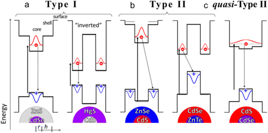 | ||
| Fig. 1 (a) Type-I, (b) Type-II, and (c) quasi-Type-II band-edge alignments between the materials in core/shell QDs. Reprinted with permission from ref. 21 Copyright (2016) American Chemical Society. | ||
In quasi-type II, the distribution of carriers is intermediate between type I and type II. One of the carriers is domain-limited in the core or shell and the other carrier is off-domain throughout the nanoparticle. In this system, it is required that the conduction or valence bands of the two have similar energy level positions, such as quasi-type II structured CdSe@CdS NCs, which are able to produce a large spectral redshift of electrons toward the shell off-domain, while having a fluorescence quantum yield close to that of type I NCs. A study by Klimov's group reported that a thin layer of ZnS shell layer grown on the surface of CdSe QDs forms a type I energy band structure in which the holes of the QDs are confined to the CdSe nucleus.23
In Fig. 2a and b, mono-disperse zinc blende CdSe@CdS core/shell NCs were synthesized by epitaxial growth of 1–6 monolayers of CdS shell onto zinc blende CdSe core NCs in one pot.24 In Fig. 2(c–e), the optical properties of QDs change with the growth of the thin shell layer, indicating that the ZnS shell layer on the CdSe QDs does not change the in-band relaxation process and the complexation of the excited electrons and holes, i.e., the electrons and holes of the I-type QDs are confined to the nucleus of the QDs, respectively.25 Kambhampati investigated the dynamics of photogenerated electron complexation in CdSe@ZnS QDs and found that it was not affected by the complexation of defect states at the surface.26 By probing the influence of the surface effect on the cooling of the in-band carriers of the QDs, it was observed that the process of the cooling of the electrons was not affected by themorphology of the surface defects, which also confirms the previously reported I-type energy band structure feature, where electrons and holes are split into two separate systems. Rosenthal et al. reported that the complexation efficiency of the surface trap defect states in CdSe@ZnSe QDs increases with the size of the quantum dot shell layer.27 This is a type II or type II energy band structure.
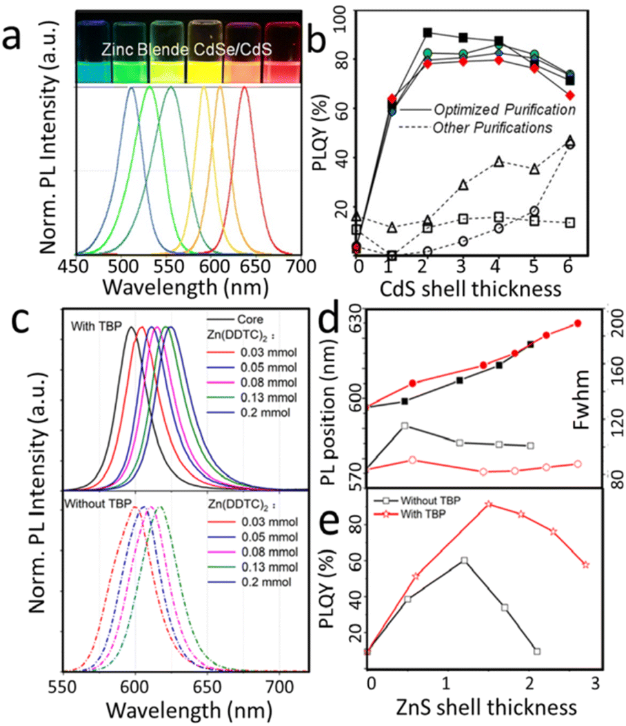 | ||
| Fig. 2 (a) Luminescence pictures under UV excitation (top) and PL spectra of zinc blende CdSe@CdS core/shell NCs with different emission wavelengths. (b) PL QY versus shell thickness for zinc blende core and core/shell NCs synthesized under different conditions. (c) Evolution of PL spectra with different ZnS shell thicknesses in CsSe@ ZnS. (d) PL properties in terms of peak position and FWHM of the emission. (e) QY value as a function of CdS shell thickness. (a and b) Reprinted with permission from ref. 24 Copyright (2012) American Chemical Society. (c and d) Reprinted with permission from ref. 25 Copyright (2022) MDPI (Basel, Switzerland). | ||
2.3 Preparation
By virtue of the research of Gao and colleagues,34 a synthetic method based on the slow decomposition of sulfhydryl ligands has gradually become the dominant method for the synthesis of core/shell-structured QDs in aqueous solution. QDs with a fluorescence efficiency of 85% were synthesized using an aqueous-phase method by encapsulating a CdS shell on the surface of the CdTe core.35 The key step in the encapsulation of the shell is the light-assisted degradation of thioglycolic acid (TGA) encapsulated on the surface of the CdTe core to slowly release S2− in solution.
All QDs prepared using the aqueous-phase method have two common features: (i) no washing of the core material prior to the growth of the shell material, which is significantly different from the formation of the shell structure using the organic synthesis route; and (ii) the establishment of the core/shell structure is accomplished at the earliest stage of quantum dot formation. Indeed, the photodegradation deposition properties of TGA are significantly better than those of mercaptopropionic acid (MPA), with which it is homologous. This is further corroborated by the fact that a significant gain in luminescence efficiency over ZnSe alone can be observed by light-assisted preparation of ZnSe/ZnS after the introduction of Zn/mercaptopropionic into the solution containing ZnSe QDs.36 In addition to the classical aqueous synthesis route, recently, Choi and his coworkers used a hydrothermal method to prepare core–shell structured QDs in aqueous solution. They used this method to prepare CdTe/CdS QDs that emit near-infrared light. In their preparation, CdCl2, NaHTe and NAC were the precursor and ligand, respectively, and NAC remained as a source of S2− for the growth of the shell structure at the late stage of the reaction, which was carried out at 200 °C. PLQY of the obtained CdTe/CdS QDs was enhanced to 62%, while the fluorescence excitation peak was red-shifted from 650 nm to 800 nm.37
At the earliest, CdS/HgS/CdS QDs were prepared by sequentially adding H2S with Hg2+ to an aqueous solution containing phosphate polymer-coated CdS. Owing to the solubility product of HgS is significantly lower than CdS, the Cd2+ in CdS is easily displaced, but the process begins at the particle surface. The thickness of the HgS shell layer can be adjusted by repeating the substitution and redeposition process in the above steps. The thickness of the CdS shell can be adjusted without affecting the HgS shell layer by introducing additional Cd2+ as well as H2S.
Surface cation exchange has also been used to prepare CdTe@HgTe core/shell structured QDs. However, once the Hg![[thin space (1/6-em)]](https://www.rsc.org/images/entities/char_2009.gif) :Cd ratio reaches a certain value, the increasing concentration of Hg2+ in the example and the counteracting effect on the Hg:Cd ratio results in the creation of an alloy quantum dot CdxHg1−xTe with a radial concentration gradient structure, rather than the core/shell structured QDs. This phenomenon is likely to result from the fact that Hg2+ and Cd2+ have almost the same ionic radius, so that the two elements each form sphalerite structures with close lattice constants, differing by only 0.3%.40,41
:Cd ratio reaches a certain value, the increasing concentration of Hg2+ in the example and the counteracting effect on the Hg:Cd ratio results in the creation of an alloy quantum dot CdxHg1−xTe with a radial concentration gradient structure, rather than the core/shell structured QDs. This phenomenon is likely to result from the fact that Hg2+ and Cd2+ have almost the same ionic radius, so that the two elements each form sphalerite structures with close lattice constants, differing by only 0.3%.40,41
The surface cation substitution method resulted in the formation of core/shell structures with different grades or gradients, which limits its application in the preparation of pure core/shell structured QDs, but makes it an interesting approach to control the optical properties of QDs by employing gradient or even pure alloy structures. Nevertheless, it is still technically difficult to directly map the spatial distribution of the component ions of QDs with a diameter of only a few nanometers. Many of the studies carried out so far up to this point have been based on conventional spectroscopy, but the resulting composite structures deserve to be scrutinized. In addition to steady-state spectroscopy, Rogach and colleagues have recently been working on a research approach that utilizes a combination of transient spectroscopy and theoretical studies to probe ion-exchange dynamics.40 Lifshitz et al. prepared SnTe@CdTe and CdTe@SnTe Core/Shell NCs by cation exchange procedure at mild conditions combined with Kirkendall Effect.39 Tight controlling of the reaction conditions allowed for redistribution of the elements throughout the NCs, i.e., outward migration of the Sn cations while the Cd cations diffuse towards the core center. The synthesis resulted in a well-organized core/shell structure (Fig. 3).
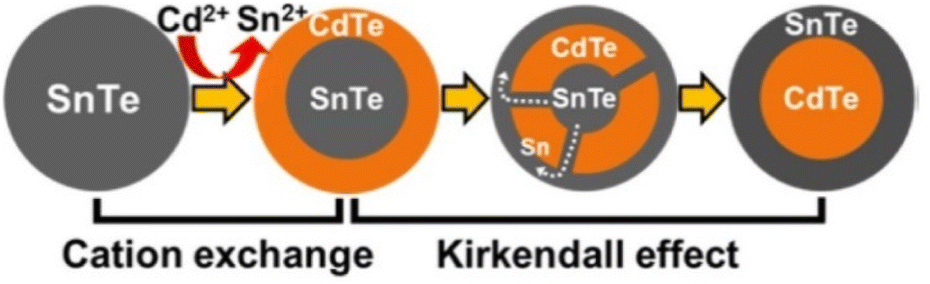 | ||
| Fig. 3 Schematic illustration of the formation of SnTe-based core/shell NCs by cation exchange reaction and the Kirkendall effect. Reprinted with permission from ref. 39 Copyright (2016) American Chemical Society. | ||
In addition to mentioned methods, intermittent provision of small amounts of cationic/anionic precursors is also a good way to prevent uniform nucleation during shell growth. For example, Cd2+-mercaptopropionic acid and HSe− were sequentially added into a reaction system to grow CdSe shell structures on the surface of mercaptopropionic acid-coated CdTe QDs (emitting an orange light with a peak at 613 nm).43–46
There are still many challenges associated with the use of aqueous phase methods for the preparation of NCs with core/shell structures. In addition, it is difficult to individually characterize the core–shell interface in heterostructures using conventional TEM because the electron densities of group II–VI semiconductors are so different. With the development of materials testing techniques, this problem was gradually being solved. For example, core–shell CdTe/CdSe and alloy CdTeSe QDs are synthesized by aqueous solvent in 2022. TEM images showed a rod-shaped core–shell structure and an elliptical alloy structure with different crystal planes competing to grow.47
3. Core/shell heterostructure based on lead halide perovskites QDs
Lead halide perovskite (CsPbX3) NCs have the advantages of high brightness, high defect tolerance, tunable emission wavelength, high color purity and high PLQY. Lead halide perovskites not only showed great application potential in photovoltaic and other optoelectronic device applications, but also performed good applications in energy conversion and biomedical directions in recent years. However, it is worth noting that the poor stability of lead halide perovskites NCs severely limits its application research.14–19 Lead halide perovskite NCs would undergo degradation or PL quenching in the presence of solvents, high temperature, humidity, light illumination and O2.48 Preparation of robust shell encapsulation to cover CsPbX3 core is important for improving the stability of lead halide perovskites.Thermal injection and supersaturation recrystallization are commonly methods for the preparation of CsPbX3 NCs. However, the stability of the prepared NCs remains poor even when the synthesis process is optimized. Preparation of robust shell encapsulation such as ZnS, SiO2, TiO2, Al2O3, PbSO4, MOFs, and polymers provided the effective strategies for improving the stability of lead halide perovskites.49–53 In Fig. 4a–c, Hou et al. prepared CsPbBr3 core–shell structure of multidentate polymer micelles by using the copolymer template synthesis method.54 The whole process was under room temperature. As showed in Fig. 4, the co-polymer polystyrene-block-poly-2-vinylpyridine was first dissolved in toluene, and then PbBr2 and CsBr were added in methanol. Within the nanoshells of the copolymer polystyrene-block poly-2-vinylpyridine formed by polydentate coordination groups, a solid-phase reaction occurs, followed by crystallization to obtain CsPbBr3 NCs. The polystyrene-block poly-2-vinylpyridine acted as a confined nanoreactor during the crystallization of perovskites by passivating the surface through the polydentate capping shells, which greatly enhances the photostability of chalcogenide in polar solvents. The NCs showed high stability in polar solvents and remained stable after 50 days with PL. In Fig. 4(d–h), CsPbBr3@ZIF-67, CsPbBr3@ZIF-8 were obtained by s directly grown of CsPbBr3 in a mixture of metal ion and imidazole precursors. The prepared CsPbBr3@ZIF composites improved photogenerated charge separation efficiency, CO2 capturing ability, and moisture stability.55
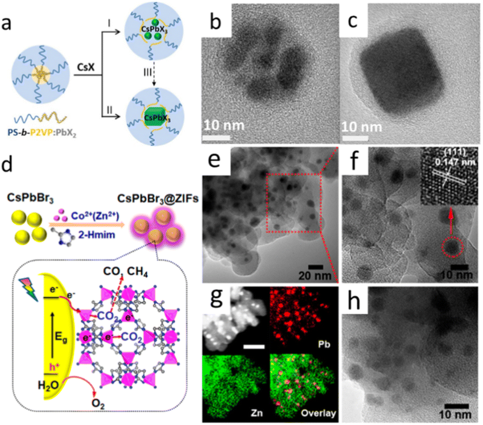 | ||
| Fig. 4 (a) Synthetic strategies for perovskite NCs using amphiphilic block copolymer micelles as nanoreactors. TEM of polymer micelles containing multiple CsPbBr3 NCs (b) and single CsPbBr3 NC (c). (d) Schematic illustration of the fabrication and CO2 photoreduction of CsPbBr3/ZIFs. (e and f) TEM images of CsPbBr3@ZIF-8. The inset of (f) is the high-resolution image of a single CsPbBr3 QD marked with a red circle. (g) High-angle annular dark-field STEM image and elemental mapping of CsPbBr3@ZIF-8. Scale bar: 50 nm. (h) TEM image of CsPbBr3@ZIF-67. (a–c) Reprinted with permission from ref. 54 Copyright (2017) American Chemical Society. (d–h) Reprinted with permission from ref. 55 Copyright (2018) American Chemical Society. | ||
In Fig. 5a, many studies have realized the assembly of CsPbX3 into a matrix. The size of prepared composites was hundreds of nanometers. The realization of encapsulation on individual CsPbX3 NPs was crucial for its use in biologically fields and optoelectronic devices. Nag et al. prepared CsPbBr3@ZnS NCs by adding extra oleylammonium bromide (OAmBr) in hot injection method. NCs maintained the high PL intensity even after being dipped in water for more than 2 days.49 Fig. 5(b–d), Zheng et al. prepared CsPbBr3@TiO2 Core/Shell NCs by the encapsulation of CsPbBr3 NCs with titanium precursor, followed by calcination at 300 °C.50
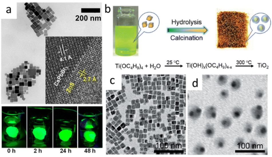 | ||
| Fig. 5 (a) TEM image of CsPbBr3@ZnS NCs. Inset shows HRTEM image of an NC near the core/shell interface and digital photographs of the films of CsPbBr3/ZnS core/shell dipped in beakers full of water and excited with UV lamp (365 nm). (b) Schematic illustration of the fabrication process for CsPbBr3@TiO2 NCs; TEM images of CsPbBr3 NCs (c) and CsPbBr3@TiO2 NCs (d). (a) Reprinted with permission from ref. 49 Copyright (2020) American Chemical Society. (b–d) Reprinted with permission from ref. 50 Copyright (2018) John Wiley & Sons. | ||
Fig. 6 showed some reported monodisperse CsPbX3@SiO2 NPs. Monodisperse CsPbX3/SiO2 and CsPbBr3/Ta2O5 Janus NPs were successfully synthesized by combining the water-triggered transformation process and sol–gel method (Fig. 6a and b). The stability against destruction by air, water, and light irradiation was dramatically improved.56 Li et al. reported a controlled hydrolysis process of tetramethoxysilane to obtain the homogeneous CsPbBr3@SiO2 NCs. Firstly, Cs4PbBr6 NCs were silanized using partially hydrolyzed tetramethoxysilane. And then, injection of water triggered the phase transformation from Cs4PbBr6 to CsPbBr3 and generation of condensation SiO2 shell.57 Another monodisperse CsPbBr3@SiO2 NCs were reported by Zhong et al. (Fig. 6c). One-pot synthesis method was used by precisely controlling the reaction temperature, precursor species, ligand ratio, and pH.58 Li. et al. prepared a homogeneous CsPbBr3@SiO2 and Janus structure by controlling the hydrolysis process of tetramethoxysilane.57 Table 1 is the summary of the reported CsPbBr3 core–shell nanocomposites in single particle level.
 | ||
| Fig. 6 (a) TEM image of CsPbBr3/SiO2 Janus NCs; (b) Schematic illustration of the formation process of CsPbBr3/SiO2 Janus NCs; (c) proposed formation process of CsPbBr3@SiO2 core–shell NPs and stability against water; (d) the TEM images of CsPbBr3@SiO2 NCs. (a and b) Reprinted with permission from ref. 56 Copyright (2017) American Chemical Society. (c) Reprinted with permission from ref. 58 Copyright (2021) Royal Society of Chemistry. (d) Reprinted with permission from ref. 57 Copyright (2021) Royal Society of Chemistry. | ||
| Type | Preparation method | Size (nm) |
|---|---|---|
| CsPbX3/SiO2 Janus | Water-triggered transformation process | Width: 11.3 |
| CsPbX3/Ta2O5 Janus | Water-triggered transformation process | Length: 14.7–23.9 |
| CsPbBr3@ZnS | Hot injection method with OAmBr | 48.7 |
| CsPbBr3@SiO2 | Water-triggered transformation process | 47 nm |
| CsPbBr3@SiO2 | One-pot | 18.2 |
| CsPbBr3@TiO2 | Calcination | Shell thick: 5 ± 3 nm |
4. Core/shell heterostructure based on noble metal NCs
4.1 Properties
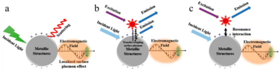 | ||
| Fig. 7 Metal enhanced fluorescence mechanism: (a) the SPR effect, (b) the plasmon coupling effect due to non-radiative interactions, (c) the intrinsic radiative decay effect. (a–c) Reprinted with permission from ref. 61 Copyright (2020) Multidisciplinary Digital Publishing Institute. | ||
Noble metal core–shell structures are materials formed by using noble metals (Au, Ag, Pt, Pb) as the core or shell, whose properties can be changed by adjusting the core–shell dimensions and chemical compositions to realize the controlled synthesis of multifunctional NPs. Using simulations and computational methodologies to examine pure Ag/Au and Ag@Au/Au@Ag core–shell NPs, it was demonstrated that even a single shell layer led to discernible changes in the electronic structure.67 Due to the wide variety of noble metal core/shell structures and the different preparation methods as well as the properties of each aspect, several typical methods for the preparation of noble metal core/shell were introduced.
4.2 Preparation
Bao et al.70 synthesized Co@Au core–shell NPs with magneto-optical properties by using the weak reduction of octadecylamine to reduce the organic gold compound on the surface of Co species in the nonpolar solvent toluene. The homogeneous and well-crystallized shell layer is more easily prepared in the presence of weak reducing agent octadecylamine and nonpolar solvent, while Au as the shell layer can provide good biocompatibility and near-infrared optical activity. Dai et al.71 prepared the ternary metal Pt@Co-core Au-shell NPs by reduction of HAuCl4 solution with NaBH4 in Pt@Co seed solution, and heat-treated them to obtain core–shell NPs in face-centered tetragonal phase. Ban et al.72 first reduced FeCl3 with Na in NMPO (1-methyl-2-pyrrolidinone) solvent to obtain a black-brown solution of Fe core particles, added a certain amount of 4-phenylpyridine protector to continue the reaction for a certain period of time, and added dropwise NMPO solution containing HAuCl4 to the core particle solution, and used the surface of the core particles to self Au3+ was reduced by the reduction of the surface of the core particles, and Au-coated Fe NPs were formed. Analysis showed that the coating of Au did not affect the magnetic properties of the core particles, and the surface plasmon resonance absorption peaks of core–shell NPs after the coating underwent an obvious red-shift phenomenon, which was shifted from 520 nm to 680 nm.
Lei and colleagues prepared SnO2@Ag and SnO2@Au core–shell NCs using a seed-mediated hydrothermal method.83,84 Hollow SnO2 NPs were first prepared by using SiO2 as a seed. SnO2 was then used as a seed to prepare SnO2@Ag with SnO2@Au. The test results of photodegradation rhodamine B experiments demonstrated that the photocatalytic properties of SnO2 were significantly improved after loading Ag and Au.85 In 2016, the Au@SnO2@Ag and Au@SnO2@Au yolk–shell NPs are synthesized via a silica seeds-mediated hydrothermal method. The catalytic results showed the synergistic effect of Au and Ag in the metal–semiconductor core shell structures, which was beneficial to the catalytic reduction of 4-nitrophenol into 4-aminophenol.86 It was shown that NPs with this structure directly affect the photophysical and photocatalytic properties of metal and semiconductor nanoclusters and enhance the rate of surface charge migration. Au@Pt NPs were synthesized by reducing HAuCl4 and H2PtCl6 with sodium citrate and ascorbic acid (AA).87 The prepared Au@Pt core/Shell NPs were used as the probe for versatile barometer biosensor.88 Lu et al. reported a novel strategy for the preparation of Au@N-CQDs@Pt NPs by reducing HAuCl4 with N-CQDs at 100 °C and reducing H2PtCl6 with AA. The remarkable advantage of the protocol was no stabilizer or surfactant agent used.89
Gamma (γ)-irradiation is also a method for realizing core–shell structures when polymers are encapsulated on top of noble metal NPs. The method involved the use of γ-irradiation to trigger a conventional free radical polymerization process of pure organic NPs and nanocomposites.91 For example, PANI γ-irradiation-induced polymerization enabled the preparation of Ag@PANI.92 The γ-irradiation triggered the interaction of aniline (ANI) and AgNO3, where Ag+ acted as an electron acceptor and is reduced when the ANI monomer was oxidized. Initial irradiation decomposes NO3− ions in AgNO3, triggering polymerization of the ANI monomer. Subsequently, Ag+ oxidized the residual oligomers, dimers, or tetramers. This complex oxidation and reduction interaction produced Ag@PANI core–shell NPs.
In addition to the above methods, there are also diffusion methods, heat treatment methods and so on, which are not introduced here. Some researchers have also selected two or more of the above methods and used them in combination, and have also achieved remarkable results.
5. Core/shell heterostructure based on QDs and noble metal NCs
Noble metal/semiconductor heterostructures have attracted the attention of lots of researchers due to their wide range of applications in the field of degrading organic pollutants. The noble metal@semiconductor hybrid NPs may maintain and further improve the properties of the individual components and even generate new synergistic effects. These properties might originate from the interface between the noble metal and the self-semiconductor. Recently, colloidal NPs with a variety of materials have been prepared by a controlled synthesis process to obtain a variety of nanoscale metal/semiconductor mixture heterostructure systems, such as dumbbell, two-sided, core/shell, and yolk/shell structures. It is shown that the loading of noble metals can effectively prevent carrier recombination between the metal and the semiconductor and improve the light trapping efficiency, thus enhancing the photocatalytic performance of the materials. In addition, the semiconductor contact can improve the plasmonic properties of metal nanostructures. This phenomenon occurs through coupling of surface plasmon or modification of the local dielectric environment. Due to the intrinsic surface plasmon resonance effect, these materials exhibit size-dependent optical properties.Metal/sulfur semiconductor core–shell structured NCs have been widely studied as a typical material system of surface plasmonic excitogen-exciton coupling interaction.93,94 Zhang et al. reported the non-epitaxial preparation of metal/semiconductor heterogeneous core–shell NCs with large lattice mismatch degree and their novel applications in light-matter-spin precise modulation.95 Compared with oxide semiconductors, II–VI semiconductors have narrower forbidden bandwidths and better absorption properties for visible light, which have unique advantages and theoretical, applied research value in photovoltaics, photocatalysis, and so on.
Zhang et al.95 proposed a novel non-epitaxial growth method and combined it with the cation exchange method to successfully prepare Au@CdS core–shell structures with a single shell layer. And after that, Au@CdS core–shell NCs were further studied using this method and found that such metal@semiconductors synthesized by the non-epitaxial growth method with a single-crystal shell layer can be used to flexibly and controllably control plasmonic resonance-exciton coupling and prolong the lifetime of excitons.96–98 In Au@CdS NCs, the semiconductor CdS forms a shell layer in direct contact on the surface of the Au core in both dimensional directions. In this way, the disadvantage of enhanced photocatalytic performance of some particles out of the field due to surface plasma-induced electromagnetic field enhancement of the heterogeneous structure because of the directionality of the surface plasma magnetic field is avoided, resulting in high catalytic performance for each nanocrystal, and leading to an increased separation of photogenerated electrons from holes.
6. Biological application
Core–shell NPs have good advantages in biological applications, such as their lower cytotoxicity, better dispersion and biocompatibility, easier binding to bioactive molecules, better thermal and chemical stability. When the desired NPs are toxic, it may cause a lot of trouble to the host tissues and organs. Coating the core surface with a layer of harmless material makes the NPs much less toxic. The shell layer not only serves as a non-toxic layer, but also improves the performance and stability of the core material. The core–shell structure can also improve the hydrophilic and hydrophobic properties of the core material and achieve better biocompatibility. In addition, the core–shell structure allows for the binding of specific types of biomolecules. Therefore, core–shell NPs are more promising for biological applications than bare NPs. The summary of the typically biomedical application of core–shell NPs was illustrated in Fig. 8.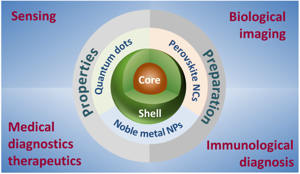 | ||
| Fig. 8 Summary of the typically biomedical applications of core–shell NPs. | ||
6.1 Sensing
The size and shape dependent QDs with color tunability confirming the significant influence in a biological system and considered as ideal probes. The former study confirmed that core–shell QDs exhibited the stronger PL and smaller full-width-half-maximum (FWHM) than bare QDs, suggesting that the core–shell QDs have the nearly uniform size distribution and good dispersion. The quantum yield (QY) of the core–shell QDs is increased by surface passivation.99 CdSe@ZnS core–shell structured QDs can be used as probes for FRET detection of blood glucose when they interact with different enzymes such as glucose oxidase. The enzyme breaks down glucose through a redox reaction in which the QDs provide electrons while the enzyme acts as an electron acceptor.100 The QDs transfer out non-radiant energy to quench the fluorescence, which corresponds to the concentration of glucose in the system. Similarly, hydrogen peroxide can be characterized by the fluorescence burst of CdSe@ZnS QDs. The emergence of such QDs makes it possible to provide a theoretical basis for an integrated nano-hybrid sensor with biocatalyst and fluorescent labelling. The sensing system has an approximate fluorescence quantum yield of 20% and excellent photostability. Core–shell structured QDs have been used for optical detection of glucose in the presence of glucose oxidase.101 The use of CdSe/ZnS core–shell structured QDs for the detection of urea when urease was used as a catalyst was reported in another study.102 This detection was based on the enhancement of fluorescence corresponding to the rate at which urea was degraded.Core–shell structured QDs have likewise been shown to be pH receptors, such as surface-modified CdSe@ZnS QDs.103 pH sensing is based on the opening of the 1,3-oxazine ring after acid or base stimulation. In the former low case, a color-carrying group (4-nitrophenyl-azophenolate) is produced by the chemical stimulation, and photogenerated electrons migrate from the quantum dot to the color-carrying group and attach to its surface, leading to quenching of the quantum dot luminescence. Since ring opening of the 1,3-oxazine ring can only occur under acidic pH conditions, the color-carrying group does not absorb visible light after its formation. Since the color-carrying group does not absorb the excitation energy of the QDs, it is an electron-poor donor, which results in an increase in quantum yield. In addition, FRET-based pH receptors are reported to consist of an amphiphilic polymer core with a pH-sensitive arylturnip acid dye wrapped around the outside, and the absorption spectra of such dyes are governed by changes in pH, so that the overall absorption spectra of the sum-shell-structured QDs also vary with pH.104
According to the sensing strategy, noble metal NPs sensors can be categorized as colorimetric, fluorescent, electrical and electrochemical, surface plasmon resonance, and surface enhanced Raman scattering (SERS). Different types of nanobiosensors relied on different properties of noble metal NPs, such as visible color change, fluorescence quenching, surface plasmon resonance, and SERS properties. LSPR properties make core/shell NCs useful in biological and chemical sensing, as changes in the local environment can be detected through shifts in the resonance wavelength. Using Ag nanowire (NW) @ZIF-8 Core@Shell NPs, Zhang et al. explored the intricate interactions between the shell thickness, spatial and energetic arrangements between probe molecules and Ag NW @ZIF-8 Core@Shell NPs core–shell substrates during SERS. The results confirmed the critical role of shell thickness in influencing the sensitivity and selectivity of SERS.105 The same result was found in Ag@SiO2 core–shell NPs.106 Liu et al. established a simple strategy for label-free SERS bioanalysis to analyze intracellular composition profiles based on Au@carbon dot (Au@CDs) nanoprobes.107 Utilizing SERS properties, core–shell structures can also be used for the detection of antibiotic pollutants in food. For example, Yang et al. designed Ag@inositol hexaphosphate@Au NPs to be used as the SERS substrate, which was realized to achieve the detection of trace penicillin G in milk. The large surface plasmon resonance of the hot spot field generated in the core–shell molecular gap extends to the surface of the NPs, leading to a synergistic enhancement of the Raman scattering effect.108 Recently, it was reported that CH3NH3PbBr3@Al2O3 core–shell NPs showed excellent uniformity and reproducibility in SERS measurements, which provided the foundation for the practical application of perovskite-based SERS probes in the biological fields.109
By capping a SiO2 shell layer of different thicknesses on the surface of Ag noble metal NPs, not only can fluorescent NPs with good dispersion and optical stability be obtained, but also their metal-enhanced fluorescence and the sensing properties of individual NPs can be fully utilized. MEF is a well-established technology, which can greatly enhance the fluorescence effect through the interaction between fluorescent substances and metals, improve the optical stability, reduce the scintillation of single-molecule fluorescence spectra, and decrease the fluorescence lifetime with the increase of the radiative decay rate of the system, and at the same time increase the transmission distance due to the transfer of fluorescence resonance energy. Different fluorescence probing experiments are carried out using this core–shell: organic fluorescence and lanthanide hybridization probing (non-covalent linkage), organic fluorescence covalent linkage probing. The results show that the fluorescent NPs with the core–shell structure have a 20-fold enhancement of their fluorescence signal and a 200-fold increase in the detectability of the particles compared to fluorescent NPs.110 Tang et al. fabricated Ag@SiO2@SiO2-RuBpy core–shell NPs for the detection of prostate-specific antigen (PSA) in both buffer and serum. PL enhancement of core–shell NPs was up to 3-fold when the separation distance between the surface of silver core and the center of the third RuBpy doped silica shell is about 10 nm (Fig. 9).111 In 2023, Maquieira et al. prepared CsPbX3@SiO2 core–shell NPs and successfully demonstrated their specific recognition of a humanized antibody (omalizumab) used in treating patients with severe allergic asthma.112 Sun et al. designed a sandwich-type electrochemical sensor for highly sensitive detection of alpha-fetoprotein (AFP) based on aptamer (Apt)-AFP-Ab interaction mode with Ag@Au core–shell NPs as a signal amplifier.113 The novel sandwich-type electrochemical sensor peroformed the high sensitivity, outstanding selectivity, and promising application prospect in bioanalysis.
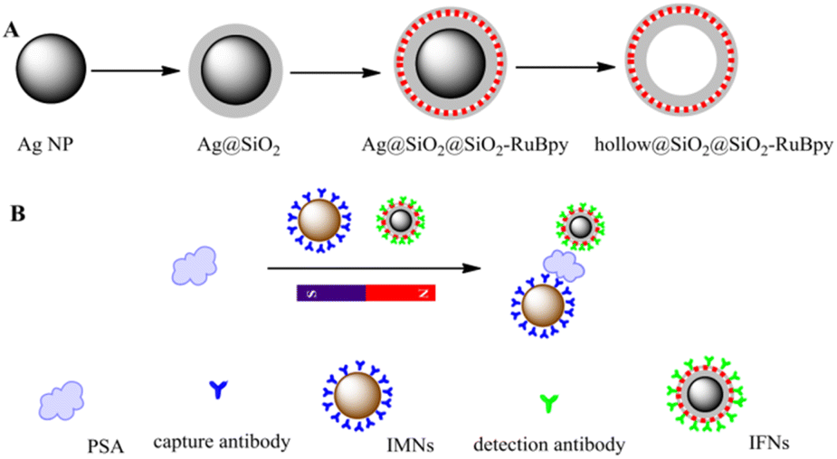 | ||
| Fig. 9 (A) Schematic illustration for synthesis of Ag@SiO2@SiO2-RuBpy and hollow@SiO2@SiO2-RuBpy. (B) Schematic illustration for the construction of the detection of PSA with the immunomagnetic nanospheres and immunofluorescent NPs. Reprinted with permission from ref. 111 Copyright (2017) Elsevier. | ||
Overall, the tailored optical properties of core/shell NCs significantly enhance their utility in analytical and biomedical applications, providing more sensitive and reliable detection methods.
6.2 Biological imaging
Core@shell NCs are widely used in bioimaging due to their superior fluorescence properties. QDs with a CdSe core and a ZnS shell, for example, exhibit high brightness and photostability, making them ideal for long-term imaging of biological specimens.Their tunable fluorescence properties make them ideal for biolabeling applications, allowing for specific tagging of cells or proteins and subsequent imaging for research and diagnostic purposes. Large number of researches applied QDs in biological imaging.72,114,115 Compared to the traditional dyes, QDs core–shell NCs possessed some special optical properties in biological imaging, such as higher extinction coefficients; higher PLQYs; less photobleaching; absorbance and emissions can be changed with size; broad excitation band narrow emission peaks; multiple QDs can be used in the same assay with minimal interference with each other. Table 2 lists the studies of QDs for in vivo and in vitro imaging and diagnostic applications according to UV-NIR tunable fluorescence, FRET, charge transfer, and surface-enhanced Raman spectroscopy (SERS).116,117
| Type | Application | Techniques | Emission |
|---|---|---|---|
| CdSe@CdS@SiO2 | Mouse fibroblast cell imaging | In vitro fluorescence | 550 nm & 630 nm |
| CdSe@ZnS | Biological detection/sensing | In vitro fluorescence | |
| CdSe@ZnS@SiO2 | Phagokinetic track imaging | In vitro fluorescence | 554 nm & 626 nm |
| CdSe@ZnS | Tumor vasculature and lung endothelium imaging | In vitro and in vivo fluorescence | <10 nm |
| CdTe@CdSe | Cancer cell lymph nodes imaging | In vivo fluorescence | Near infrared |
| CdSe@ZnS | Maltose binding protein | In vitro FRET | 560 nm |
| CsPbBr3@SiO2 | Bioimaging | In vitro | 518 nm |
Recent years, CsPbBr3 have emerged as new class of candidate for many biomedical applications, such as ultrahigh-resolution bioimaging, biosensing, and flow cytometry, owing to their excellent PL properties.118–120 CsPbBr3 NCs and hollow graphitic carbon nitride nanospheres nanocomposite was prepared as DNA probe for the estimation of CD44 expression on the MCF-7 cell surface (Fig. 10a).118 Park et al. prepared CsPbBr3@SiO2 core–shell NPs for cell imaging and drug delivery (Fig. 10b). The results demonstrated CsPbBr3@SiO2 NPs were nontoxic, making them available for in vitro cell imaging. Using doxorubicin, it was confirmed that CsPbBr3@SiO2 NPs can be used for drug loading and delivery.121 In 2024, CsPbBr3@SiO2 performed the high biocompatibility and showed the great application potential in the field of bioimaging.122
 | ||
| Fig. 10 (a) Schematic Illustration of the in situ assembly of CsPbBr3 NCs into hollow graphitic carbon nitride nanospheres as the DNA probe for the targeting of CD44 receptors on the MCF-7 cell surface and the double signal amplification. (b) Schematic of the proposed mechanism of drug loading and release in the CsPbBr3@SiO2@Dox-embedded HeLa cells, as well as the confocal fluorescence image of HeLa cells after incubation with Dox-loaded CsPbBr3@SiO2 core–shell NCs. (a) Reprinted with permission from ref. 118 Copyright (2020) American Chemical Society. (b) Reprinted with permission from ref. 121 Copyright (2020) Royal Society of Chemistry. | ||
Used in drug delivery and imaging, Au@silica core–shell NPs leverage the biocompatibility of silica and the unique optical properties of gold. Noble metal core–shell NPs performed enhanced properties and functionality because of their special use in medical imaging, such as X-ray and optical imaging, and fluorescence.123
6.3 Medical diagnostics and therapeutics
Hussain et al. reported a one-pot method for the preparation of InP@ZnS QDs with controllable morphology, size and fast reaction at low temperature. The prepared QDs can be tuned from the blue region to the near infrared and can be used as cellular fluorescent probes after surface modification.124 By virtue of the plasmonic properties, the fluorescence peak position of Fe3O4@Au and Fe3O4@Au@Ag core–shell structured QDs can be arbitrarily red-shifted to 560 nm or blue-shifted to 501 nm by varying the thickness of the shell layer. This unique magnetic and optical properties has a great potential for applications in the field of biomedical applications, such as magnetic resonance imaging, photothermal therapy, controlled drug delivery, protein separation, biosensors, DNA detection, and immunosensors.82,125 By functionalizing the shell with specific ligands, these NCs can target particular biomolecules or cells, enhancing the sensitivity of SERS for biomedical diagnostics. In addition, core/shell structures can be designed to provide Raman signals along with other imaging modalities, offering comprehensive diagnostic capabilities. Tian et al. demonstrated Au@MIL-88(Fe) NPs exhibited high performance in various diagnosis imaging methods, especially potentially allowing decreased levels of exposure of stroke patients to CT imaging radiation (Fig. 11).126 In 2019, multi-functional Fe3O4@Au NPs were synthesized for cancer diagnosis and therapy. The Fe3O4@Au-doxorubicin-mPEG/PEG-folic acid NPs performed the increased cellular uptake through a folate-receptor-mediated endocytosis, resulting in the improved cytotoxic effect on the cancer cells. Under the laser irradiation, the cytotoxicity of Fe3O4@Au-DOX-mPEG/PEG-FA NPs was enhanced owing to the photothermal effect of Au shell.127 The noble metal core shell NPs have been used in the surgical treatment of tumors as well as in the imaging of lymph nodes in large mammals, sometimes with the attachment of a polydentate phosphate coating in order to improve their solubility, stability, and dispersion in serum.128 The biocompatibility and functionalization potential of core@shell NCs allow for the targeted delivery of therapeutic agents.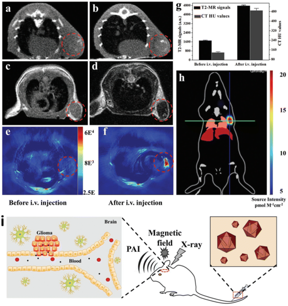 | ||
| Fig. 11 In vivo triple-modality imaging of U87MG-subcutaneous tumor-bearing mice. (a and b) CT images of mice before and 12 h after i.v. injection with Au@MIL-88(Fe); (c and d) T2-weighted MR images of mice before and after i.v. injection with Au@MIL-88(Fe); (e and f) in vivo PA imaging of tumors in mice before and 12 h after i.v. injection with Au@MIL-88(Fe); (g) quantified MRI and CT signals of tumors from mice before and 12 h after i.v. injection with Au@MIL-88(Fe); (h) bioluminescent imaging of tumor. (i) Schematic illustration of the Application to multimodality imaging-based tumor diagnosis. (a–i) Reprinted with permission from ref. 126 Copyright (2017) John Wiley & Sons. | ||
Thermal plasma NPs provided a novel and important avenue for photothermal therapy in medicine. Most of the reported core–shell NPs are spherical. In recent years, exploration of non-spherical (spherical, rod, cubic, etc.) core–shell NPs has confirmed their unique properties.129–133 For example, the anisotropic shape of rod-shaped core–shell NPs can affect interactions with light.134 Star-shaped core–shell NPs showed the larger specific surface area and distinctive SPR, which makes them valuable in catalysis and sensing applications.135,136 The special geometry in the structure of gold nanorods gives it a great advantage in biosensing, imaging and diagnostic applications. Wang et al.76 used a modified Stöber method to uniformly coat Au nanorods with a layer of SiO2, which was self-assembled on PVP-modified silicon wafers to form a homogeneous Au rod@SiO2 membrane, and the amino groups on the membrane could be covalently linked to sheep anti-human immunoglobulin forming a covalent linkage, providing a good reaction model for color detection of IgG. More impressively, the protein recognition process on the Au rod@SiO2 membranes can be monitored either by visual observation or by changes in light absorption. Wu et al. designed a TiN@Au core–shell nanorod. The photothermal properties of the nanorod in the near-infrared (NIR) band were investigated using COMSOL Multiphysics software and finite element method. The results show that the TiN@Au and Au@TiN core–shell structures exhibit better photothermal properties than pure TiN nanorods of the same volume in the NIR band.137 AuNC@CPs (Au nanocages@polymer) were prepared by dialysis of gold nanocages and coordination polymers. Due to the excellent photothermal, photoacoustic and magnetic properties of AuNC@CPs in solution, AuNC@CPs are used for near-infrared (NIR) -driven photothermal therapy (PTT) in vivo under the guidance of photoacoustic (PA) and magnetic resonance (MR) imaging.138 Due to its excellent performance, noble metal core–shell NPs will become a promising nanoprobe in the field of therapeutics. [198Au]Au@SiO2 core–shell NPs were synthesized for hyperthermia. The resulting core–shell NPs exhibited near-infrared (NIR) absorption at 750 nm and radiochemical purity of 99.91%.139
6.4 Immunological diagnosis
Core@shell NCs have been increasingly utilized in immunological diagnosis due to their unique properties, such as high surface area, tunable physical and chemical characteristics, and enhanced signal sensitivity. Core@shell NCs can significantly enhance the sensitivity of immunoassays. Recent studies highlight several applications of core@shell NCs in this field. For instance, a novel electrochemical immunosensor for early breast cancer detection was developed using 3D urchin-like core–shell Au@PdCu NCs. This sensor achieved high sensitivity in detecting carbohydrate antigen 15–3 (CA15–3), a key biomarker for breast cancer.140,141 Another study focused on the synthesis of tetrahexahedral Au–Pd core–shell NCs integrated with reduced graphene oxide (rGO). This composite was used to fabricate a highly sensitive sensor for detecting epinephrine, an important diagnostic marker in various medical conditions.142 Au NPs coated with a silica shell can amplify the signal in enzyme-linked immunosorbent assay (ELISA) tests, allowing for the detection of lower levels of antigens or antibodies. Bifunctional core@shell Au@Pt/Au NPs are presented as novel tags in Immunosensing for the determination of an Alzheimer's disease biomarker in human plasma sample. The synergy between Au and Pt metals improved the sensitivity of the detection.143,144 Additionally, advancements in the synthesis of core@shell NCs have led to enhanced immunological responses. For example, chiral Au@Pd NCs with intrinsic chiral surfaces have been shown to produce enantiomer-dependent immunological responses, which can be crucial for the selective targeting of specific biomolecules in immunological assays.140 The label-free Immunosensor of gold platinum@ graphene QDs (AuPt@GQDs) core–shell NPs were prepared for ultrasensitive and rapid recognition of trace levels of escherichia coli from contaminated food.145 Core@shell NCs based on QDs are particularly promising for immunological diagnosis. The bright fluorescence of QDs can improve the sensitivity of immunoassays, enabling the detection of low-abundance biomarkers. QDs can be conjugated with antibodies or antigens to serve as fluorescent probes for detecting specific biomolecules.146 QDs used as fluorescent labels in immunoassays provide high sensitivity and multiplexing capability due to their tunable emission wavelengths. This allows for the simultaneous detection of multiple targets in a single assay.147 There are three types of immunoassays using QDs, which is ELISA, lateral flow assays, and flow cytometry. QDs can replace traditional enzyme-linked detection systems to provide a more stable and sensitive readout. QDs can be incorporated into lateral flow test strips for point-of-care diagnostics, offering rapid and quantitative results. In this year, Gu et al. obtained graphene oxide (GO)-based magnetic fluorescent nanofilm (GF@DQD-APBA) with enhanced magnetic/fluorescence properties and universal capture ability for multiple viruses through the electrostatic adsorption of one layer of density-controlled Fe3O4 NPs and thousands of small CdSe/ZnS-MPA QDs on a monolayer GO sheet followed by chemical coupling with APBA on the QD surface (Fig. 12).148 QDs conjugated to antibodies can be used in flow cytometry to analyze cell populations with high sensitivity and specificity. Besides, magnetic core@shell NCs can be used to separate specific cells or biomolecules from complex mixtures. This is particularly useful in immunomagnetic separation techniques, where magnetic NPs conjugated with antibodies can isolate specific cell types from blood samples.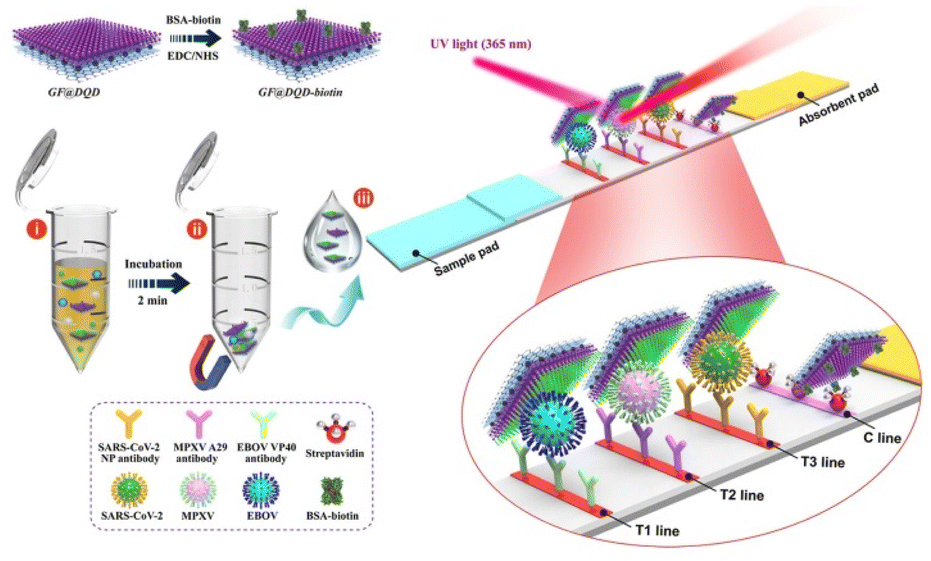 | ||
| Fig. 12 Schematic of the preparation of GF@DQD biotin tag and proposed LFIA biosensor for multiplex and ultrasensitive monitoring of EBOV, MPXV, and SARS-CoV-2 antigens. Reprinted with permission from ref. 148 Copyright (2024) American Chemical Society. | ||
These innovations demonstrate the potential of core@shell NCs to significantly improve the sensitivity and specificity of immunological diagnostics, paving the way for early and accurate detection of various diseases.
7. Conclusions and outlook
7.1 Conclusions
In this review, the core–shell structures dominated by QDs and noble metal NCs were summarized. The core–shell NCs discussed in this review have either both the core and shell made of a quantum dot or noble metal nanomaterials, or one of the core or shell structures is a quantum dot or noble metal NCs. Thus, depending on the material properties used, the core–shell structures are mainly categorized into (i) quantum dot based core–shell structures (ii) noble metal based core–shell structures, (iii) metal halide perovskites core–shell structures, (iv) quantum dot-precious metal core–shell structures. The above core–shell structure NCs performed good applications in medical or biological fields.7.2 Perspective and challenge
It has been found that noble metal NPs and QDs have many excellent properties, and combining the unique properties with other functional materials can help to develop new materials with multi functionality and open up new applications, which has become a new hot spot in the field of nanomaterials research. At present, preliminary progress has been made on the preparation of various noble metal or QDs core–shell NPs with different compositions and properties, but how to realize the controllable synthesis of the core particle size, shell thickness, geometric uniformity, characterization, and give full play to their multifunctionality are still the hotspots and difficulties in the current scientific research work, which still need the unremitting efforts of the majority of researchers. Core/shell heterogeneous provides a broad idea for the preparation of multi-component composites and unlimited possibilities for the development of materials science.Among many research directions, biosynthesis in particular offers the attraction of a green bio-factory for synthesizing QDs in a mild physiological environment, thus demonstrating the biocompatibility and bio-functionality of QDs without any additional steps. An in-depth study of metal sulfide QDs has shown that the formation process still leaves much to be further explored. These would open up the possibility of preparing biocompatible QDs with tunable optical properties, especially in combination with the biological functions of natural or modified microorganisms, as a way to synthesize quantum dot probes with specific targeting functions. Currently, the latter is still in its infancy, but offers a huge scope for future research to exploit the potential of such bio-factories in advance. We hope that our efforts on this review would be able to contribute to a better understanding and further development on the synthesis, properties, and biological applications of core shell NPs.
Data availability
No primary research results, software or code have been included and no new data were generated or analysed as part of this review.Author contributions
Xi Wang conceived the review and written the original manuscript. Peng Wang collected the literature and modified the original manuscript. Meng Li reviewed the review and provided the funding acquisition. Jian Li corrected and edited the manuscript. All authors were involved in writing and revising the manuscript.Conflicts of interest
There are no conflicts to declare.Acknowledgements
This work was supported by the projects from the Doctoral research fund project in Shandong Jianzhu University (X22033Z); the National Natural Science Foundation of China (No. 52270200); the Youth Innovation Technology Project of Higher School in Shandong Province (2023KJ125); The Introduction and Cultivation Plan for Young Innovative Talents of Colleges and Universities by the Education Department of Shandong Province.References
- A. Vaneski, J. Schneider, A. S. Susha, A. L. Rogach and J. Photoch, Photobio. C, 2014, 19, 52–61 CrossRef CAS.
- S. Balakrishnan, M. J. Bonder and G. C. Hadjipanayis, J. Magn. Magn. Mater., 2009, 321, 117–122 CrossRef CAS.
- V. Salgueiriño-Maceira and M. A. Correa-Duarte, Adv. Mater., 2007, 19, 4131–4144 CrossRef.
- I. V. Chepkasov, A. D. Radina and A. G. Kvashnin, Nanoscale, 2024, 16, 5870–5892 RSC.
- S. D. Adhikari, A. F. G. Reyes, S. Paul, J. Torres, B. Escuder, I. Mora-Seró and S. Masi, Chem. Sci., 2023, 14, 8984–8999 RSC.
- P. Scodeller, V. Flexer, R. Szamocki, E. J. Calvo, N. Tognalli, H. Troiani and A. Fainstein, J. Am. Chem. Soc., 2008, 130, 12690–12697 CrossRef CAS PubMed.
- S. Laurent, D. Forge, M. Port, A. Roch, C. Robic, L. Vander Elst and R. N. Muller, Chem. Rev., 2008, 108, 2064–2110 CrossRef CAS PubMed.
- E. Yan, Y. Ding, C. Chen, R. Li, Y. Hu and X. Jiang, Chem. Commun., 2009, 2718–2720 RSC.
- A. K. Gupta and M. Gupta, Biomaterials, 2005, 26, 3995–4021 CrossRef CAS PubMed.
- X. Michalet, F. F. Pinaud, L. A. Bentolila, J. M. Tsay, S. Doose, J. J. Li, G. Sundaresan, A. Wu, S. Gambhir and S. Weiss, Science, 2005, 307, 538–544 CrossRef CAS PubMed.
- M. De, P. S. Ghosh and V. M. Rotello, Adv. Mater., 2008, 20, 4225–4241 CrossRef CAS.
- R. Ghosh Chaudhuri and S. Paria, Chem. Rev., 2012, 112, 2373–2433 CrossRef CAS.
- M. Kouhnavard, S. Ikeda, N. A. Ludin, N. B. A. Khairudin, B. V. Ghaffari, M. A. Mat-Teridi, M. A. Ibrahim, S. Sepeai and K. Sopian, Renewable Sustainable Energy Rev., 2014, 37, 397–407 CrossRef CAS.
- N. J. Jeon, H. Na, E. H. Jung, T.-Y. Yang, Y. G. Lee, G. Kim, H.-W. Shin, S. Il Seok, J. Lee and J. Seo, Nat. Energy, 2018, 3, 682–689 CrossRef CAS.
- S. A. Veldhuis, P. P. Boix, N. Yantara, M. Li, T. C. Sum, N. Mathews and S. G. Mhaisalkar, Adv. Mater., 2016, 28, 6804–6834 CrossRef CAS PubMed.
- H. Wang and D. H. Kim, Chem. Soc. Rev., 2017, 46, 5204–5236 RSC.
- Y. C. Kim, K. H. Kim, D.-Y. Son, D.-N. Jeong, J.-Y. Seo, Y. S. Choi, I. T. Han, S. Y. Lee and N.-G. Park, Nature, 2017, 550, 87–91 CrossRef CAS.
- Q. Chen, J. Wu, X. Ou, B. Huang, J. Almutlaq, A. A. Zhumekenov, X. Guan, S. Han, L. Liang and Z. Yi, Nature, 2018, 561, 88–93 CrossRef CAS.
- J. H. Heo, D. H. Shin, J. K. Park, D. H. Kim, S. J. Lee and S. H. Im, Adv. Mater., 2018, 30, 1801743 CrossRef.
- Z. Li, F. Chen, L. Wang, H. Shen, L. Guo, Y. Kuang, H. Wang, N. Li and L. S. Li, Chem. Mater., 2018, 30, 3668–3676 CrossRef CAS.
- J. M. Pietryga, Y.-S. Park, J. Lim, A. F. Fidler, W. K. Bae, S. Brovelli and V. Klimov, Chem. Rev., 2016, 116, 10513–10622 CrossRef CAS.
- W. M. Girma, M. Z. Fahmi, A. Permadi, M. A. Abate and J.-Y. Chang, J. Mater. Chem. B, 2017, 5, 6193–6216 RSC.
- S. A. Ivanov, A. Piryatinski, J. Nanda, S. Tretiak, K. R. Zavadil, W. O. Wallace, D. Werder and V. I. Klimov, J. Am. Chem. Soc., 2007, 129, 11708–11719 CrossRef CAS.
- W. Nan, Y. Niu, H. Qin, F. Cui, Y. Yang, R. Lai, W. Lin and X. Peng, J. Am. Chem. Soc., 2012, 134, 19685–19693 CrossRef CAS.
- J. Li, H. Zheng, Z. Zheng, H. Rong, Z. Zeng and H. Zeng, Nanomaterials, 2022, 12, 2969 CrossRef CAS.
- P. Kambhampati, J. Phys. Chem. C, 2011, 115, 22089–22109 CrossRef CAS.
- M. D. Garrett, M. J. Bowers, J. R. McBride, R. L. Orndorff, S. J. Pennycook and S. J. Rosenthal, J. Phys. Chem. C, 2008, 112, 436–442 CrossRef CAS.
- L. Jing, S. V. Kershaw, Y. Li, X. Huang, Y. Li, A. L. Rogach and M. Gao, Chem. Rev., 2016, 116, 10623–10730 CrossRef CAS.
- O. Chen, J. Zhao, V. P. Chauhan, J. Cui, C. Wong, D. K. Harris, H. Wei, H.-S. Han, D. Fukumura and R. K. Jain, Nat. Mater., 2013, 12, 445–451 CrossRef CAS.
- H. Shen, H. Wang, Z. Tang, J. Z. Niu, S. Lou, Z. Du and L. S. Li, CrystEngComm, 2009, 11, 1733–1738 RSC.
- J. Zheng, F. Huang, S. Yin, Y. Wang, Z. Lin, X. Wu and Y. Zhao, J. Am. Chem. Soc., 2010, 132, 9528–9530 CrossRef CAS.
- S. Yin, F. Huang, J. Zhang, J. Zheng and Z. T. J. o. P. C. C. Lin, J. Phys. Chem. C, 2011, 115, 10357–10364 CrossRef CAS.
- X. Lv, X. Xue, Y. Huang, Z. Zhuang and Z. Lin, Phys. Chem. Chem. Phys., 2014, 16, 11747–11753 RSC.
- H. Bao, Y. Gong, Z. Li and M. Gao, Chem. Mater., 2004, 16, 3853–3859 CrossRef CAS.
- P. Zrazhevskiy, M. Sena and X. Gao, Chem. Soc. Rev., 2010, 39, 4326–4354 RSC.
- A. Shavel, N. Gaponik and A. Eychmüller, J. Phys. Chem. B, 2004, 108, 5905–5908 CrossRef CAS.
- D. Zhao, Z. He, W. Chan and M. M. Choi, J. Phys. Chem. C, 2009, 113, 1293–1300 CrossRef CAS.
- R. D. Robinson, B. Sadtler, D. O. Demchenko, C. K. Erdonmez, L.-W. Wang and A. P. Alivisatos, Science, 2007, 317, 355–358 CrossRef CAS.
- Y. Jang, D. Yanover, R. K. Capek, A. Shapiro, N. Grumbach, Y. Kauffmann, A. Sashchiuk and E. Lifshitz, J. Phys. Chem. Lett., 2016, 7, 2602–2609 CrossRef CAS PubMed.
- S. Gupta, O. Zhovtiuk, A. Vaneski, Y. C. Lin, W. C. Chou, S. V. Kershaw and A. L. Rogach, Part. Part. Syst. Charact., 2013, 30, 346–354 CrossRef CAS.
- E. Groeneveld, L. Witteman, M. Lefferts, X. Ke, S. Bals, G. Van Tendeloo and C. de Mello Donega, ACS Nano, 2013, 7, 7913–7930 CrossRef CAS PubMed.
- S. Rawalekar, S. Kaniyankandy, S. Verma and H. N. Ghosh, J. Phys. Chem. C, 2011, 115, 12335–12342 CrossRef CAS.
- R. Zeng, T. Zhang, J. Liu, S. Hu, Q. Wan, X. Liu, Z. Peng and B. Zou, Nanotechnology, 2009, 20, 095102 CrossRef PubMed.
- Y. Xia and C. Zhu, Analyst, 2008, 133, 928–932 RSC.
- J. Wang and H. Han, J. Colloid Interface Sci., 2010, 351, 83–87 CrossRef CAS.
- Y. Zhang, Y. Li and X. P. Yan, Small, 2009, 5, 185–189 CrossRef CAS PubMed.
- J. Wang, L. Wang, X. Su and R. Chen, J. Alloys Compd., 2022, 920, 165907 CrossRef CAS.
- J. Shamsi, A. S. Urban, M. Imran, L. De Trizio and L. Manna, Chem. Rev., 2019, 119, 3296–3348 CrossRef CAS.
- V. K. Ravi, S. Saikia, S. Yadav, V. V. Nawale and A. Nag, ACS Energy Lett., 2020, 5, 1794–1796 CrossRef CAS.
- Z. J. Li, E. Hofman, J. Li, A. H. Davis, C. H. Tung, L. Z. Wu and W. Zheng, Adv. Funct. Mater., 2018, 28, 1704288 CrossRef.
- C. Jin, G. Kailun, Z. Yihua, Z. Jingrun, W. Yuanwei, S. Jianhua, T. Adrian, L. Chunzhong and W. Gang, Chem. Commun., 2018, 54, 8064–8067 RSC.
- A. Loiudice, S. Saris, E. Oveisi, D. T. Alexander and R. Buonsanti, Angew. Chem., Int. Ed., 2017, 56, 10696–10701 CrossRef CAS PubMed.
- V. K. Ravi, R. A. Scheidt, A. Nag, M. Kuno and P. V. Kamat, ACS Energy Lett., 2018, 3, 1049–1055 CrossRef CAS.
- S. Hou, Y. Guo, Y. Tang and Q. Quan, ACS Appl. Mater. Interfaces, 2017, 9, 18417–18422 CrossRef CAS PubMed.
- Z.-C. Kong, J.-F. Liao, Y.-J. Dong, Y.-F. Xu, H.-Y. Chen, D.-B. Kuang and C.-Y. Su, ACS Energy Lett., 2018, 3, 2656–2662 CrossRef CAS.
- H. Hu, L. Wu, Y. Tan, Q. Zhong, M. Chen, Y. Qiu, D. Yang, B. Sun, Q. Zhang and Y. Yin, J. Am. Chem. Soc., 2018, 140, 406–412 CrossRef CAS PubMed.
- M. Li, X. Zhang and P. Yang, Nanoscale, 2021, 13, 3860–3867 RSC.
- Q. Zhong, M. Cao, H. Hu, D. Yang, M. Chen, P. Li, L. Wu and Q. Zhang, ACS Nano, 2018, 12, 8579–8587 CrossRef CAS PubMed.
- D. Ntirikwendera, S. Mukeshimana and J. C. Uwamahoro, OALibJ, 2024, 11, e11603 Search PubMed.
- H. T. Beier, C. B. Cowan, I.-H. Chou, J. Pallikal, J. E. Henry, M. E. Benford, J. B. Jackson, T. A. Good and G. L. Coté, Plasmonics, 2007, 2, 55–64 CrossRef CAS.
- M. A. Badshah, N. Y. Koh, A. W. Zia, N. Abbas, Z. Zahra and M. W. Saleem, Nanomaterials, 2020, 10, 1749 CrossRef CAS.
- M. Rycenga, C. M. Cobley, J. Zeng, W. Li, C. H. Moran, Q. Zhang, D. Qin and Y. Xia, Chem. Rev., 2011, 111, 3669–3712 CrossRef CAS PubMed.
- T. Chung, S.-Y. Lee, E. Y. Song, H. Chun and B. Lee, Sensors, 2011, 11, 10907–10929 CrossRef CAS.
- A. Puchkova, C. Vietz, E. Pibiri, B. Wünsch, M. a. Sanz Paz, G. P. Acuna and P. Tinnefeld, Nano Lett., 2015, 15, 8354–8359 CrossRef CAS.
- J.-W. Liaw, H.-Y. Tsai and C.-H. Huang, Plasmonics, 2012, 7, 543–553 CrossRef CAS.
- K. Ray, R. Badugu and J. R. Lakowicz, Langmuir, 2006, 22, 8374–8378 CrossRef CAS PubMed.
- L. H. dos Santos, F. D. Kiss, A. C. Ferraz and R. Miotto, J. Phys. Chem. C, 2024, 128, 10751–10760 CrossRef CAS.
- X. W. Lou, C. Yuan, E. Rhoades, Q. Zhang and L. A. Archer, Adv. Funct. Mater., 2006, 16, 1679–1684 CrossRef.
- V. Chiozzi and F. Rossi, Nanoscale Adv., 2020, 2, 5090–5105 RSC.
- Y. Bao, H. Calderon and K. M. Krishnan, J. Phys. Chem. C, 2007, 111, 1941–1944 CrossRef CAS.
- J. Dai, Y. Du and P. Yang, Z. Anorg. Allg. Chem., 2006, 632, 1108–1111 CrossRef CAS.
- Z. Ban, Y. A. Barnakov, F. Li, V. O. Golub and C. O'Connor, J. Mater. Chem., 2005, 15, 4660–4662 RSC.
- P. Sudeep, K. Takechi and P. V. Kamat, J. Phys. Chem. C, 2007, 111, 488–494 CrossRef CAS.
- A. S. Nair, V. Suryanarayanan, T. Pradeep, J. Thomas, M. Anija and R. Philip, Mater. Sci. Eng., B, 2005, 117, 173–182 CrossRef.
- H. Sakai, T. Kanda, H. Shibata, T. Ohkubo and M. Abet', J. Am. Chem. Soc., 2006, 128, 4944–4945 CrossRef CAS PubMed.
- C. Wang, Z. Ma, T. Wang and Z. Su, Adv. Funct. Mater., 2006, 16, 1673–1678 CrossRef CAS.
- J. L. Wang, Q. Fan, M. Suzuki, I. S. Suzuki, M. H. Engelhard, Y. Lin, N. Kim, J. Q. Wang and C. J. Zhong, J. Phys. Chem. B, 2005, 109, 21593–21601 CrossRef PubMed.
- R. Zanella, A. Sandoval, P. Santiago, V. A. Basiuk and J. M. Saniger, J. Phys. Chem. B, 2006, 110, 8559–8565 CrossRef CAS.
- C. Loo, A. Lin, L. Hirsch, M.-H. Lee, J. Barton, N. Halas, J. West and R. Drezek, Technol. Cancer Res. Treat., 2004, 3, 33–40 CrossRef CAS.
- J.-H. Kim, H.-W. Chung and T. R. Lee, Chem. Mater., 2006, 18, 4115–4120 CrossRef CAS.
- L. Wang, J. Luo, M. M. Maye, Q. Fan and C. J. Zhong, J. Mater. Chem., 2005, 15, 1821–1832 RSC.
- Z. Xu, Y. Hou and S. Sun, J. Am. Chem. Soc., 2007, 129, 8698–8699 CrossRef CAS PubMed.
- M. Lei, W. Wu, L. Sun, Q. Tian, C. Jiang and X. Xiao, Colloids Surf., A, 2015, 482, 276–282 CrossRef CAS.
- K. Deng, H. Lu, Z. Shi, Q. Liu and L. Li, ACS Appl. Mater. Interfaces, 2013, 5, 7845–7851 CrossRef CAS PubMed.
- W. Wu, L. Liao, S. Zhang, J. Zhou, X. Xiao, F. Ren, L. Sun, Z. Dai and C. Jiang, Nanoscale, 2013, 5, 5628–5636 RSC.
- M. Lei, W. Wu, S. Yang, X. Zhang, Z. Xing, F. Ren, X. Xiao and C. Jiang, Part. Part. Syst. Charact., 2016, 33, 212–220 CrossRef CAS.
- Z. Zhu, Z. Guan, S. Jia, Z. Lei, S. Lin, H. Zhang, Y. Ma, Z. Q. Tian and C. J. Yang, Angew. Chem., Int. Ed., 2014, 53, 12503–12507 CrossRef CAS PubMed.
- Q. Fu, Z. Wu, D. Du, C. Zhu, Y. Lin and Y. Tang, ACS Sens., 2017, 2, 789–795 CrossRef CAS PubMed.
- S. Sun, Y. Wang, T. Guo, X. Yuan, D. Zhang, Z. Xue, X. Zhou and X. Lu, J. Alloys Compd., 2019, 793, 635–645 CrossRef CAS.
- J. Zhang, M. Post, T. Veres, Z. J. Jakubek, J. Guan, D. Wang, F. Normandin, Y. Deslandes and B. Simard, J. Phys. Chem. B, 2006, 110, 7122–7128 CrossRef CAS PubMed.
- M. M. Ghobashy, Nanocomposites, 2017, 3, 42–46 CrossRef CAS.
- S. S. Gasaymeh and N. N. ALmansoori, Results Phys., 2020, 16, 102882 CrossRef.
- S. Deka, A. Falqui, G. Bertoni, C. Sangregorio, G. Poneti, G. Morello, M. D. Giorgi, C. Giannini, R. Cingolani and L. Manna, J. Am. Chem. Soc., 2009, 131, 12817–12828 CrossRef CAS PubMed.
- J.-S. Lee, E. V. Shevchenko and D. V. Talapin, J. Am. Chem. Soc., 2008, 130, 9673–9675 CrossRef CAS PubMed.
- J. Zhang, Y. Tang, K. Lee and M. Ouyang, Science, 2010, 327, 1634–1638 CrossRef CAS PubMed.
- J. Zhang, Y. Tang, K. Lee and M. Ouyang, Nature, 2010, 466, 91–95 CrossRef CAS PubMed.
- Q. Zhao, M. Ji, H. Qian, B. Dai, L. Weng, J. Gui, J. Zhang, M. Ouyang and H. Zhu, Adv. Mater., 2014, 26, 1387–1392 CrossRef CAS PubMed.
- S. Lambright, E. Butaeva, N. Razgoniaeva, T. Hopkins, B. Smith, D. Perera, J. Corbin, E. Khon, R. Thomas and P. Moroz, ACS Nano, 2014, 8, 352–361 CrossRef CAS PubMed.
- R. Ratnesh and M. S. Mehata, Spectrochim. Acta, Part A, 2017, 179, 201–210 CrossRef CAS PubMed.
- M. N. Stojanovic and D. Stefanovic, Nat. Biotechnol., 2003, 21, 1069–1074 CrossRef CAS PubMed.
- R. Gill, L. Bahshi, R. Freeman and I. Willner, Angew. Chem., Int. Ed., 2008, 120, 1700–1703 CrossRef.
- C.-P. Huang, Y.-K. Li and T.-M. Chen, Biosens. Bioelectron., 2007, 22, 1835–1838 CrossRef CAS PubMed.
- M. Tomasulo, I. Yildiz, S. L. Kaanumalle and F. M. Raymo, Langmuir, 2006, 22, 10284–10290 CrossRef CAS PubMed.
- M. A. Shivkumar, L. S. Inamdar, M. H. K. Rabinal, B. G. Mulimani, G. M. A. Rao and S. R. Inamdar, Open J. Phys. Chem., 2013, 3, 40–48 CrossRef.
- S. Lin, B. Chen, Y. Xu, Z. Li, Y. Liao, J. Wang, P. Yu and Y. Zhang, Mater. Today Chem., 2024, 36, 101923 CrossRef CAS.
- J. Ma, W. Yan, B. Liu and J. Yang, J. Nanopart. Res., 2024, 26, 126 CrossRef CAS.
- Y. Zheng, X. Xiao, Z. Li, Y. Shao, J. Chen, Z. Guo, H. Zhong and Z. Liu, JoVE, 2023, e65524 CAS.
- T. Wang, H. Wang, A. Zhu, Y. Wu, X. Guo, Y. Wen and H. Yang, Sens. Actuators, B, 2021, 346, 130591 CrossRef CAS.
- Z. Zhuang, J. Wang, J. Huang, R. Hong, C. Tao, Q. Wang, H. Lin, Z. Han, D. Zhang and S. Zhuang, J. Phys. Chem. C, 2024, 128, 10120–10132 CrossRef CAS.
- K. Aslan, M. Wu, J. R. Lakowicz and C. D. Geddes, J. Am. Chem. Soc., 2007, 129, 1524–1525 CrossRef CAS PubMed.
- D.-D. Xu, Y.-L. Deng, C.-Y. Li, Y. Lin and H.-W. Tang, Biosens. Bioelectron., 2017, 87, 881–887 CrossRef CAS PubMed.
- C. Collantes, W. Teixeira, V. González-Pedro, M.-J. Bañuls, P. Quintero-Campos, S. Morais and Á. Maquieira, Dalton Trans., 2023, 52, 18464–18472 RSC.
- X. Pei, J. Liu, Y. Zhang, Y. Huang, Z. Li, X. Niu, W. Zhang and W. Sun, Microchim. Acta, 2024, 191, 414 CrossRef CAS PubMed.
- H. Zare, M. Marandi, S. Fardindoost, V. K. Sharma, A. Yeltik, O. Akhavan, H. V. Demir and N. Taghavinia, Nano Res., 2015, 8, 2317–2328 CrossRef CAS.
- J. Duan, Y. Feng, G. Yang, W. Xu, X. Li, Y. Liu and J. Zhao, Ind. Eng. Chem. Res., 2009, 48, 1468–1475 CrossRef CAS.
- S. Kim, Y. T. Lim, E. G. Soltesz, A. M. De Grand, J. Lee, A. Nakayama, J. A. Parker, T. Mihaljevic, R. G. Laurence and D. M. Dor, Nat. Biotechnol., 2004, 22, 93–97 CrossRef CAS PubMed.
- D. Bera, L. Qian, T.-K. Tseng and P. H. Holloway, Materials, 2010, 3, 2260–2345 CrossRef CAS.
- Y. Cao, W. Zhu, H. Wei, C. Ma, Y. Lin and J.-J. Zhu, Anal. Chem., 2020, 92, 4123–4130 CrossRef CAS PubMed.
- H. Zhang, X. Wang, Q. Liao, Z. Xu, H. Li, L. Zheng and H. Fu, Adv. Funct. Mater., 2017, 27, 1604382 CrossRef.
- X. Yang, Y. Gao, Z. Ji, L.-B. Zhu, C. Yang, Y. Zhao, Y. Shu, D. Jin, Q. Xu and W.-W. Zhao, Anal. Chem., 2019, 91, 9356–9360 CrossRef CAS PubMed.
- P. Kumar, M. Patel, C. Park, H. Han, B. Jeong, H. Kang, R. Patel, W.-G. Koh and C. Park, J. Mater. Chem. B, 2020, 8, 10337–10345 RSC.
- J. Xue, D. Chen, H. Zhang, L. Guo, P. Li, D. Han, X. Guo, Q. Duan and S. Sang, ACS Appl. Nano Mater., 2024, 7, 3997–4007 CrossRef CAS.
- N. Li, P. Zhao and D. Astruc, Angew. Chem., Int. Ed., 2014, 53, 1756–1789 CrossRef CAS PubMed.
- S. Hussain, N. Won, J. Nam, J. Bang, H. Chung and S. Kim, Chemphyschem, 2009, 10, 1466–1470 CrossRef CAS PubMed.
- S. V. Salihov, Y. A. Ivanenkov, S. P. Krechetov, M. S. Veselov, N. V. Sviridenkova, A. G. Savchenko, N. L. Klyachko, Y. I. Golovin, N. V. Chufarova and E. K. Beloglazkina, J. Magn. Magn. Mater., 2015, 394, 173–178 CrossRef CAS.
- W. Shang, C. Zeng, Y. Du, H. Hui, X. Liang, C. Chi, K. Wang, Z. Wang and J. Tian, Adv. Mater., 2016, 29, 1604381 CrossRef PubMed.
- S. Rajkumar and M. Prabaharan, Colloids Surf., B, 2019, 174, 252–259 CrossRef PubMed.
- M. H. Oh, N. Lee, H. Kim, S. P. Park, Y. Piao, J. Lee, S. W. Jun, W. K. Moon, S. H. Choi and T. Hyeon, J. Am. Chem. Soc., 2011, 133, 5508–5515 CrossRef CAS PubMed.
- J. Zhao, S. Xue, R. Ji, B. Li and J. Li, Chem. Soc. Rev., 2021, 50, 12070–12097 RSC.
- D. Avşar, H. Ertürk and M. P. Mengüç, J. Quant. Spectrosc. Radiat. Transfer, 2020, 241, 106684 CrossRef.
- G. B. Kassahun, Adv. NanoBiomed Res., 2019, 2, 1–13 Search PubMed.
- P. Bhatia, S. Verma and M. Sinha, Phys. Lett. A, 2019, 383, 2542–2550 CrossRef CAS.
- W. Brullot, R. Strobbe, M. Bynens, M. Bloemen, P.-J. Demeyer, W. Vanderlinden, S. De Feyter, V. K. Valev and T. Verbiest, Mater. Lett., 2014, 118, 99–102 CrossRef CAS.
- P. R. Sajanlal, T. S. Sreeprasad, A. K. Samal and T. Pradeep, Nano Rev., 2011, 2, 5883 CrossRef PubMed.
- C. L. Nehl, H. Liao and J. H. Hafner, Nano Lett., 2006, 6, 683–688 CrossRef CAS PubMed.
- A. Silvestri, L. Lay, R. Psaro, L. Polito and C. Evangelisti, Chem.–Eur. J., 2017, 23, 9732–9735 CrossRef CAS PubMed.
- Q. Luo, Y. Liu, N. Chen and X. Wu, Int. J. Therm. Sci., 2024, 204, 109242 CrossRef CAS.
- C. Yan, L. Cui, Q. Yang, X. Zhou, L. Pan, X. Zhang, H. Yang, Z. Zhou and S. Yang, J. Mater. Chem. B, 2017, 5, 8761–8769 RSC.
- A. Fikri, L. D. Pertiwi, A. M. Forentin, D. M. Sari, S. Juliyanto, A. R. Putra, V. Y. Susilo, M. B. Febrian, H. Setiawan, A. Pujiyanto, R. Ritawidya and Y. Yulizar, J. Radioanal. Nucl. Chem., 2024 DOI:10.1007/s10967-024-09549-9.
- F.-X. Wu, F.-H. Li, X.-L. Lv, Q.-X. Zhang, G.-B. Xu and W.-X. Niu, Rare Met., 2024, 43, 225–235 CrossRef CAS.
- D.-N. Chen, A.-J. Wang, J.-J. Feng and T. Y. Cheang, Microchim. Acta, 2023, 190, 353 CrossRef CAS PubMed.
- W. Dong, Y. Ren, Z. Bai, J. Jiao, Y. Chen, B. Han and Q. Chen, J. Colloid Interface Sci., 2018, 512, 812–818 CrossRef CAS PubMed.
- A. Iglesias-Mayor, O. Amor-Gutierrez, A. Novelli, M.-T. Fernandez-Sanchez, A. Costa-García and A. de la Escosura-Muniz, Anal. Chem., 2020, 92, 7209–7217 CrossRef CAS PubMed.
- P. Pang, X. Teng, M. Chen, Y. Zhang, H. Wang, C. Yang, W. Yang and C. Barrow, Sens. Actuators, B, 2018, 266, 400–407 CrossRef CAS.
- T. Das and S. Das, ACS Biomater. Sci. Eng., 2024, 10, 4018–4034 CrossRef CAS PubMed.
- F. Ren, F. Wang, A. Baghdasaryan, Y. Li, H. Liu, R. Hsu, C. Wang, J. Li, Y. Zhong and F. Salazar, Nat. Biomed. Eng., 2024, 8, 726–739 CrossRef CAS PubMed.
- X. Shao, Z. Dong, S. Zhang, Y. Qiao, H. Zhang and H. Guo, J. Pharm. Biomed. Anal., 2024, 243, 116096 CrossRef CAS PubMed.
- C. Wang, Q. Yu, S. Zheng, W. Shen, J. Li, C. Xu and B. Gu, ACS Nano, 2024, 18, 16752–16765 CrossRef CAS PubMed.
| This journal is © The Royal Society of Chemistry 2024 |