 Open Access Article
Determining non-radiative decay rates in TADF compounds using coupled transient and steady state optical data
Stefano
Sem
 *ab,
Sandra
Jenatsch
 a,
Kleitos
Stavrou
c,
Andrew
Danos
 c,
Andrew P.
Monkman
 c and
Beat
Ruhstaller
ad
aFluxim AG, Katharina-Sulzer-Platz 2, 8400 Winterthur, Switzerland. E-mail: stefano.sem@fluxim.com
bUniversity of Augsburg, Augsburg, Germany
cDepartment of Physics, Durham University, South Road, DH1 3LE, UK
dZurich University of Applied Sciences, 8400 Winterthur, Switzerland
First published on 14th February 2022
Abstract
Thermally-activated delayed fluorescence (TADF) compounds are promising materials used in emissive layers of organic light-emitting diodes (OLEDs). Their main benefit is that they allow the internal quantum efficiency of the OLED to reach up to 100% by converting non-radiative triplet states into radiative singlets. Besides the importance of having a high reverse intersystem-crossing rate, which governs triplet conversion, minimizing the non-radiative decay processes is also extremely important to reach high efficiency. In this study we provide a new method to quantify not only the most important decay rates involved in the TADF process, but also the non-radiative decay rates of both singlet and triplet states individually from transient and steady state experimental optical data. In addition, the different contribution that the two non-radiative decay pathways have on the internal quantum efficiency is investigated. Finally, the method is applied to experimental data from two TADF materials.
Introduction
Thermally-activated delayed fluorescence (TADF) materials have been the subject of considerable recent scientific progress in the OLED community.1,2 While with simple fluorescent emitters the physical limit of internal quantum efficiency (IQE) is 25%, TADF emitters can reach 100% because of the efficient recycling of excitons from non-radiative triplet states to radiative singlets.3,4 Such a large IQE can be obtained by designing emissive materials with high reverse intersystem crossing rate (krisc) and low non-radiative decay rate (knr).5In recent years, the TADF mechanism has been deeply investigated and the underlying processes elucidated. The transition from triplet to singlet state, which governs the TADF process, has been found to occur in a complex manner where multiple excited states are involved (charge-transfer and local-excited states) and additional phenomena play a crucial role (spin–orbit and vibronic-coupling).6,7
Despite the complexity of the TADF process, the emissive properties of new materials are frequently characterized using a simpler model where only three states are considered: the ground state (S0), the first excited singlet (S1) and triplet states (T1).8 The three-state model was considered in detail by Haase et al. and used to directly fit transient photoluminescence (TrPL) decay measurements on TADF films.9,10 With their method they can quantify the key rates involved in the process (kf, kisc, krisc) as parameters in a set of ordinary differential equations (ODE), providing a simple method to evaluate TADF emitters. Nonetheless, their method assumes no non-radiative decay from the triplet state, and while that was confirmed experimentally for the specific materials they examined, it is unlikely to be true in general.
Another recent study based on the three-level model by Tsuchiya et al. addresses the same topic by deriving the analytic exact solution of the model. However, when applying this to experimental results, the non-radiative decay rates of singlet or triplet states cannot be fit uniquely without additional experimental data or are simply assumed to be absent.10
The work of Vázquez et al. reports on a proposed new method to calculate rISC rates,11 but this more specialised technique was not used in this work.
In this study we investigate the effect of TADF rates on the device efficiency. We start our analysis by writing the expression of the EQE of an OLED:
| EQE = ηoutηrecηS/TPLQY |
In the optimal case, TADF emitters can exhibit a PLQY equal to 100% when there is no significant non-radiative decay from either singlet or triplet states, which implies an ELQY of 100%.13,14 Instead, when non-radiative decays are present (either from a singlet or triplet state) both PLQY and ηS/T decrease, causing a reduction of the EQE.15,16 In this more realistic case, it is important to be able to allocate where the non-radiative decay is originating from.
In the first part of the study, we highlight the importance of considering non-radiative decay processes and its influence on the EQE. Interestingly, we find that the ELQY may decrease to 50% with respect to the PLQY depending strongly on the relative distribution of non-radiative rates between singlet and triplet. Hence, knowing those rates is essential to predict the potential performance of TADF emitters. In a second step we define a fitting method to do this, which takes both TrPL and steady state PLQY data as input to determine all the excitonic rates. Finally, the method is applied to experimental data of two recent TADF emitters: 25ACA (2,5-bis(9,9-dimethyl-9,10-dihydroacridin-10-yl)benzonitrile) and 26ACA (2,6-bis(9,9-dimethyl-9,10-dihydroacridin-10-yl)benzonitrile).17 From the extracted rates we observe that all the rates are similar apart from the singlet non-radiative decay rate which is almost two orders of magnitude larger in 25ACA than in 26ACA.
Model and methods
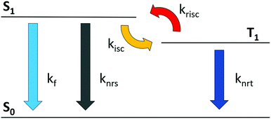
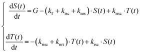
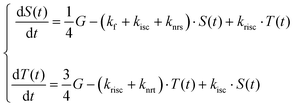
As a first step, we define the system of ODEs describing the time dependent TADF process where, for simplicity, we consider the involvement of only two excited states, singlet and triplet (see Fig. 1)8,10 wherein knrs and knrt denote the non-radiative transfer rates for singlet and triplet states, respectively.In Table 1 we compare the ODEs describing the evolution of the singlet and triplet populations (S(t) and T(t)) for both optical and electrical excitation and provide an expression for the steady-state singlet population (![[S with combining macron]](https://www.rsc.org/images/entities/i_char_0053_0304.gif) ) as well as for the PLQY and ELQY in the two cases. In Table 1 the term A has been introduced for better readability (A = (krisc + knrt)/kisc). The steady state solutions, indicated in the second line of Table 1, can be easily calculated by imposing the steady state condition to the systems. The quantum yield is defined as the number of emitted photons divided by the number of generated excitons G. The emitted photons can be expressed by the sum of the multiplication between the steady state population of each emissive state and its radiative decay rate, in our case we have assumed phosphorescence to be absent and therefore only the singlet state contributes to photon emission (kf ×
) as well as for the PLQY and ELQY in the two cases. In Table 1 the term A has been introduced for better readability (A = (krisc + knrt)/kisc). The steady state solutions, indicated in the second line of Table 1, can be easily calculated by imposing the steady state condition to the systems. The quantum yield is defined as the number of emitted photons divided by the number of generated excitons G. The emitted photons can be expressed by the sum of the multiplication between the steady state population of each emissive state and its radiative decay rate, in our case we have assumed phosphorescence to be absent and therefore only the singlet state contributes to photon emission (kf × ![[S with combining macron]](https://www.rsc.org/images/entities/i_char_0053_0304.gif) , as indicated in the third line of Table 1). In the case of optical excitation, G generates only singlet states, while under electrical excitation one quarter of the generated exciton are singlets and three quarters are triplets. Having different generation terms in the two systems has the effect of modifying the steady state population of singlet
, as indicated in the third line of Table 1). In the case of optical excitation, G generates only singlet states, while under electrical excitation one quarter of the generated exciton are singlets and three quarters are triplets. Having different generation terms in the two systems has the effect of modifying the steady state population of singlet ![[S with combining macron]](https://www.rsc.org/images/entities/i_char_0053_0304.gif) and triplet
and triplet ![[T with combining macron]](https://www.rsc.org/images/entities/i_char_0054_0304.gif) states, and this causes the PLQY and ELQY to be different in the two cases. Imposing steady-state conditions gives expressions for the relevant singlet state populations and corresponding ELQY and PLQY.
states, and this causes the PLQY and ELQY to be different in the two cases. Imposing steady-state conditions gives expressions for the relevant singlet state populations and corresponding ELQY and PLQY.
The equations shown in Table 1 are solved numerically with Python. The global fit described in the next section is performed using the Trust Region Reflective algorithm. The numerical analysis of the 0D ODEs presented here is a simpler alternative to the full electro-optical models in Setfos, where coupled 1D partial differential equations (PDEs) are solved for studying exciton dynamics and their interaction with electrical charges and the optical cavity.18–20
Result and discussion
In this section we first show the change between PLQY and ELQY calculated with specific decay rates. Afterwards, we define the systems of equations describing two additional typical experimental technique used to characterize TADF films, PLQY with oxygen and TrPL. Finally, we use global fitting, with which we can estimate the entire set of decay rates from the three experimental results.Dependence of ELQY/PLQYs on knrad,s/t and populations.
In this section we will analyse the dependence of the PLQY and ELQY with knrs and knrt. The crucial point of the analysis is that the rate of non-radiative decay events is defined as the multiplication between rate constant and population, namely knrsS or knrtT, respectively. In TADF OLEDs the population of triplets is usually much larger than the population of singlets,3 and therefore knrt produces a larger number of non-radiative decay events with respect to knrs. Moreover, as we have already seen, the steady state populations in case of optical and electrical excitation are different and therefore the number of non-radiative decay events will also change. In other words, conclusions drawn from the popular analysis of the luminescence quantum yield by optical excitation may be misleading and the electrical excitation present in OLED display and lighting applications will be affected more strongly by realistic values of non-radiative decay rates.The main message delivered in this section is: supposing a certain PLQY is measured experimentally, which value of ELQY is expected?
To reply to this question, we assume the PLQY to be known and, from the PLQY formula in Table 1, we calculate the non-radiative decay rates which lead to this PLQY value. Subsequently, the ELQY is calculated with the rates found. In this analysis we assume kf, kisc, krisc to be known.
To calculate the non-radiative decay rates from the optical system we can simply revert the PLQY equation in Table 1 and express knrs as a function of knrt (eqn (1)). The solution of this equation is not unique since both knrs and knrt are unknown, however, since the goal of this work is to give an idea about the impact of the two rates on the yields, we can simply solve this equation with a fixed knrt finding the corresponding knrs. In this way we will end up with many different couples (knrs; knrt) which are solutions of the equation. The ELQY is then calculated with the formula in Table 1 for each couple.
 | (1) |
In Fig. 2 the result of this analysis considering four PLQYs is shown. On the x-axis the quantity knrs/knr = knrs/(knrs + knrt) is used, denoting the relative strength of non-radiative singlet decay. Obviously, the PLQY remains constant at the chosen value for each point on the x-axis. We can observe that when knrs = 0 → knr = knrt we have the lowest ELQY while when knrt = 0 → knr = knrs the ELQY is maximized and coincides with the PLQY. It is important to note that in the case of high PLQY values, the difference with the ELQY is small (Fig. 2a), 82–90% in case of PLQY = 90%. Instead, considering a PLQY of 60%, as in Fig. 2d, we can see that the calculated ELQY decreases significantly, from 60% to 31% (roughly a 50% reduction). This means that a film with an experimentally measured PLQY of 60% might exhibit an ELQY as low as 31%.
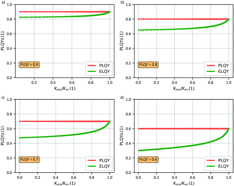 | ||
| Fig. 2 For a fixed PLQY of 0.9 (a), 0.8 (b), 0.7 (c), 0.6 (d) the ELQY is calculated for all possible couples knrs–knrt which are solutions of eqn (1). In this calculation the other rates have been supposed known (kf = 107 s−1, kisc = 107 s−1 and krisc = 106 s−1). | ||
The result of this parameter variation illustrates the importance of non-radiative triplet decay as it strongly affects the luminescence quantum yield for electrical excitation. This effect must be considered when estimating the EQE of TADF devices, especially when PLQY differs significantly from 100%.
PLQY with oxygen (PLQYO2)
In the previous analysis we solved one equation with two unknowns, ending up with many knrs–knrt solutions of the system. To continue our analysis and extract all excitonic parameters we need to take into account additional experimental results.A common experiment used to characterize TADF compounds is the measurement of the PLQYO2.21,22 The presence of oxygen molecules has the effect of quenching the triplet states and therefore the contribution of delayed emission is not present, causing the PLQYO2 to be lower than the PLQY. In this condition, the equation of triplet can be removed from the optical system indicated in Table 1 and thus the sole equation of singlet states remains.
 | (2) |
As before, the PLQY can be calculated from the steady state solution.
 | (3) |
In the above formula we made the approximation that the entire triplet population is quenched by oxygen. We must note that this is a good approximation when the host permeability to oxygen is high.23 If this condition is not met the calculated PLQY will underestimate the value measured experimentally. Singlet quenching in the presence of oxygen is also possible24,25 but in a much smaller scale compared to triplet quenching. Therefore this effect is not taken into consideration.
Modelling of a TrPL experiment
Until now, we have assumed knowledge of the other rates involved in the ODE systems, namely kf, kisc and krisc. An established way to estimate these quantities is to perform a TrPL experiment and perform a mathematical fit.Following the analysis of Haase et al.9 we defined the system indicated in eqn (4). In contrast to their work we introduce non-radiative decay for singlets and triplets in the ODE system.
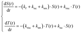 | (4) |
Global fit
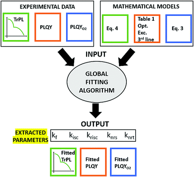
We have now a set of three systems of differential equations which describes three experiments: PLQY (Table 1-optical excitation-3rd line), PLQYO2 (eqn (3)) and TrPL (eqn (4)). The estimation of the decay rates (kf, kisc, krisc, knrs and knrt) can now be performed with an appropriate fitting algorithm.The best approach when dealing with different experiments described by equations having several parameters in common is to perform a global fit, where the three sets of experimental data are fitted at the same time. This approach allows the extracted parameters to be more reliable since a potential correlation between them will be reduced.26
In Fig. 3 a schematic representation of the inputs/outputs of the fitting algorithm is shown.
It is important to mention that the three experimental results are of different shape from a numerical point of view, the TrPL consist of a curve with several data points, while the PLQYs have only one data point each. Clearly, the optimization algorithm will tend to reach a solution where the TrPL experiment is well fitted at the expenses of the other two if each fitting target has the same weight. In order to obtain a well-balanced fit, it is necessary to include different weights of the error for the three experiments, essentially, we should give more importance to the PLQY values.
Experimental results
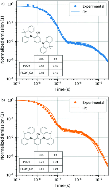
The methodology is applied to experimental data from two host–guest systems, in the form of films, one containing 25ACA and the other 26ACA as emissive TADF molecule at 1 wt% in Zeonex as host.The experimental data for PLQY and PLQYO2 for the two films are indicated in Table 2. Fig. 4 shows the experimental data and the resulting fit. The fit reproduces almost perfectly the TrPL and PLQYs of the experimental data. In both cases, but most predominantly in the case of 26ACA, the PLQYO2 fit shows a discrepancy with the experimental value (0.12 instead of 0.15 in 25ACA and 0.21 instead of 0.41 in 26ACA). A possible explanation could be that in eqn (2) and (3) we considered the entire population of triplets to be quenched by oxygen, while in the experiment this might not be entirely the case.27 Consistent with this possibility the fit of PLQYO2 has considerably larger error.
| PLQY | PLQYO2 | |
|---|---|---|
| 25ACA | 0.42 | 0.15 |
| 26ACA | 0.71 | 0.41 |
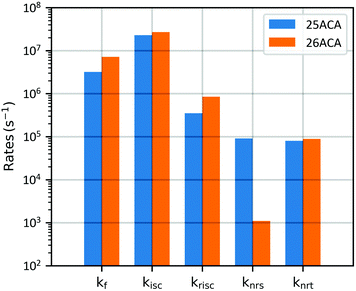
The extracted parameters are indicated in Table 3 and shown in Fig. 5 for a direct comparison. The results suggest that kf, kisc, and krisc are all higher in 26ACA, similar to what was previously reported in DPEPO (25ACA: kf = 3.6E6 s−1; kisc = 1.5E7 s−1; krisc = 0.6E6 s−1. 26ACA: kf = 4.3E6 s−1; kisc = 2.7E7 s−1; krisc = 1.8E6 s−1).17 Uniquely to this work, we are also able to estimate the non-radiative decay rate of the singlet and triplet states, showing that knrs in 26ACA is almost two orders of magnitude smaller than in 25ACA while knrt is quite similar between the two. We must observe that the error associated to the non-radiative decay rate of singlet states is quite large compared to the other parameters. This fact is however expected because the non-radiative decay rate is the parameter which influences the experimental results the least: knrs mainly influences the prompt decay of the TrPL and PLQYO2 but since kf and kisc are usually two or three orders of magnitude larger, knrs has a comparably smaller effect. Therefore, it is more difficult for the fitting algorithm to estimate it properly.
| Extracted parameters | 25ACA | 26ACA |
|---|---|---|
| k f [s−1] | (3.2 ± 0.3) 106 | (7.2 ± 0.1) 106 |
| k isc [s−1] | (23 ± 0.1) 106 | (26.8 ± 0.5) 106 |
| k risc [s−1] | (3.5 ± 0.1) 105 | (8.5 ± 0.2) 105 |
| k nrs [s−1] | (9.1 ± 36) 104 | (1.1 ± 5.8) 103 |
| k nrt [s−1] | (8.0 ± 0.1) 104 | (8.9 ± 0.5) 104 |
As a final step we can calculate the expected ELQY for the two films, using the formula indicated in Table 1 with the extracted rates. The resulting ELQY, or maximum IQE, is 0.36 for 25ACA and 0.69 for 26ACA. The traditional way of calculating the IQE, assuming ηS/T = 1, would have predicted values of 0.42 and 0.71 for 25ACA and 26ACA, respectively. It is important to note that in this case the difference between PLQYs and ELQYs is minimal, but as showed in Fig. 2 it can be much larger depending on the specific rates considered.
Additional analysis and further modelling with a full electro-optical model
The model we defined is not particularly complex, only two excited states are considered, and phosphorescence is assumed to be absent. The complexity of the system can be increased by including additional excited states. However, this possibility requires new equations to be defined, which will increase the number of unknown parameters significantly. Having a large number of free parameters in a fitting algorithm will probably result in overfitting which would decrease the confidence of the extracted values. We therefore followed the premise of making the model as complex as necessary but as simple as possible. Nevertheless, we would like to briefly discuss here how the proposed model can be extended in future studies.Additional complexity can be introduced by including the radiative decay of the triplet state. In case phosphorescence is found to contribute significantly to the emission (i.e., if clearly observed from transient spectral data at low temperatures) it could be easily considered in the model by modifying the triplet equation with a kph term.
Other phenomena that could be included in the model are annihilation processes such as singlet–singlet, singlet–triplet and triplet–triplet annihilation. As these processes are exciton-density dependent, it would be beneficial to include experiments performed with different laser intensities. Moreover, in this case the equations become non-linear and therefore it is necessary to quantify the exciton density from independent experiments or simulations.28
Finally, the effect of exciton–polaron quenching should be considered for a complete analysis and powerful prediction of the maximum IQE in an OLED device. The model extension would be feasible. But clearly, additional data such as transient electroluminescence from full devices29,30 or TrPL on full or single-carrier devices29 would be required as fitting target. Also, the number of charge carriers would need to be provided, for example by using device simulations.31
Once the entire set of excitonic parameters are extracted with this simple ODE method, they could be used in a 1D full electro-optical model such as Setfos.20 This option would allow to simulate the OLED by taking into account the actual optical characteristics of the entire stack and important phenomena like spatial dependency of the radiative decay rates (Purcell factor) and charge/exciton distribution, which is required when calculating the annihilation and exciton-quenching losses.1,26 Further details can be added by including the 3D Master-Equation model, which consider non-local exciton energy transfer (Förster, Dexter), energy transfer across layer interfaces and correlated/uncorrelated energetic disorder.32
Conclusions
In this work we studied a TADF system described as a three-levels model including non-radiative decays of singlet and triplet states. The influence of non-radiative processes on the EQE has been deeply investigated and quantified.A global fitting algorithm which takes as input data from transient and steady state experiments (TrPL, PLQY and PLQYO2) was introduced. Besides the determination of kf, kisc and krisc, which themselves are easily inferable with a simple TrPL fit, this algorithm allows the extraction of knrs and knrt, which are usually more difficult to assess separately.
Finally, we applied this fitting method to experimental results of two emissive films. The result of our analysis shows that the rates are quite similar among the two materials apart from the non-radiative decay of singlet states which is almost two orders of magnitude larger in 25ACA than in 26ACA.
This study aims to provide a new and simple method to estimate all the relevant processes in TADF emitter systems, allowing a better estimation of the maximal EQE in a real TADF OLED.
Author contributions
S. S. performed writing – original draft, conceptualization, formal analysis and methodology. S. J. performed writing – original draft, conceptualization, supervision. K. S. and A. D. performed data curation and writing – review and editing. A. P. M. performed supervision and writing – review and editing. B. R. performed writing – original draft and supervision.Conflicts of interest
There are no conflicts to declare.Acknowledgements
We acknowledge founding from the Marie Skłodowska-Curie Actions (MSCA) via the Innovative Training Network (ITN) TADFlife (GA 812872). We thank Dalius Gudeika and Juozas Grazulevicius from Kaunas University of Technology for providing the materials and Wolfgang Brütting for fruitful discussions.Notes and references
- M. Regnat, K. P. Pernstich, K. H. Kim, J. J. Kim, F. Nüesch and B. Ruhstaller, Routes for Efficiency Enhancement in Fluorescent TADF Exciplex Host OLEDs Gained from an Electro-Optical Device Model, Adv. Electron. Mater., 2020, 6(2), 1–8, DOI:10.1002/aelm.201900804.
- C. Mayr, S. Y. Lee, T. D. Schmidt, T. Yasuda, C. Adachi and W. Brütting, Efficiency enhancement of organic light-emitting diodes incorporating a highly oriented thermally activated delayed fluorescence emitter, Adv. Funct. Mater., 2014, 24(33), 5232–5239, DOI:10.1002/adfm.201400495.
- A. Endo, K. Sato and K. Yoshimura, et al., Efficient up-conversion of triplet excitons into a singlet state and its application for organic light emitting diodes, Appl. Phys. Lett., 2011, 98(8), 2011–2014, DOI:10.1063/1.3558906.
- H. Nakanotani, T. Higuchi and T. Furukawa, et al., High-efficiency organic light-emitting diodes with fluorescent emitters, Nat. Commun., 2014, 5(May), 1–7, DOI:10.1038/ncomms5016.
- H. Uoyama, K. Goushi, K. Shizu, H. Nomura and C. Adachi, Highly efficient organic light-emitting diodes from delayed fluorescence, Nature, 2012, 492(7428), 234–238, DOI:10.1038/nature11687.
- T. J. Penfold, F. B. Dias and A. P. Monkman, The theory of thermally activated delayed fluorescence for organic light emitting diodes, Chem. Commun., 2018, 54(32), 3926–3935, 10.1039/c7cc09612g.
- M. Hempe, N. A. Kukhta and A. Danos, et al., Vibrational Damping Reveals Vibronic Coupling in Thermally Activated Delayed Fluorescence Materials, Chem. Mater., 2021, 33(9), 3066–3080, DOI:10.1021/acs.chemmater.0c03783.
- C. Baleizão and M. N. Berberan-Santos, Thermally activated delayed fluorescence as a cycling process between excited singlet and triplet states: Application to the fullerenes, J. Chem. Phys., 2007, 126(20), 204510, DOI:10.1063/1.2734974.
- N. Haase, A. Danos and C. Pflumm, et al., Kinetic Modeling of Transient Photoluminescence from Thermally Activated Delayed Fluorescence, J. Phys. Chem. C, 2018, 122(51), 29173–29179 CrossRef CAS.
- Y. Tsuchiya, S. Diesing and F. Bencheikh, et al.Exact Solution of Kinetic Analysis for Thermally Activated Delayed Fluorescence Materials, published online 2021:1–41. https://chemrxiv.org/articles/preprint/Exact_Solution_of_Kinetic_Analysis_for_Thermally_Activated_Delayed_Fluorescence_Materials/14178113.
- R. J. Vázquez, J. H. Yun and A. K. Muthike, et al., New Direct Approach for Determining the Reverse Intersystem Crossing Rate in Organic Thermally Activated Delayed Fluorescent (TADF) Emitters, J. Am. Chem. Soc., 2020, 142(18), 8074–8079, DOI:10.1021/jacs.0c01225.
- A. Köhler and H. Bässler, Electronic Processes in Organic Semiconductors: An Introduction, 2015 DOI:10.1002/9783527685172.
- T. A. Lin, T. Chatterjee and W. L. Tsai, et al., Sky-Blue Organic Light Emitting Diode with 37% External Quantum Efficiency Using Thermally Activated Delayed Fluorescence from Spiroacridine-Triazine Hybrid, Adv. Mater., 2016, 28(32), 6976–6983, DOI:10.1002/adma.201601675.
- K. Stavrou, L. G. Franca and A. P. Monkman, Photophysics of TADF Guest-Host Systems: Introducing the Idea of Hosting Potential, ACS Appl. Electron. Mater., 2020, 2(9), 2868–2881, DOI:10.1021/acsaelm.0c00514.
- J. M. Ha, S. H. Hur, A. Pathak, J. E. Jeong and H. Y. Woo, Recent advances in organic luminescent materials with narrowband emission, NPG Asia Mater., 2021, 13(1), 53, DOI:10.1038/s41427-021-00318-8.
- M. Y. Wong and E. Zysman-Colman, Purely Organic Thermally Activated Delayed Fluorescence Materials for Organic Light-Emitting Diodes, Adv. Mater., 2017, 29(22), 1605444, DOI:10.1002/adma.201605444.
- A. Danos, D. Gudeika and N. Kukhta, et al., Not the Sum of their Parts: Understanding Multi-Donor Interactions in Symmetric and Asymmetric TADF Emitters, J. Mater. Chem. C, 2021 10.1039/D1TC04171A.
- B. Perucco, N. A. Reinke, D. Rezzonico, E. Knapp, S. Harkema and B. Ruhstaller, On the exciton profile in OLEDs-seamless optical and electrical modeling, Org. Electron., 2012, 13(10), 1827–1835, DOI:10.1016/j.orgel.2012.05.053.
- S. Stefano, J. Sandra and S. Prakhar, et al.Analysing the effect of thermally activated delayed fluorescence emitter concentration variations in organic light-emitting diodes. [Manuscript in preparation].
- A. G. Fluxim, Switzerland, see http://www.fluxim.com for simulation software Setfos.
- P. Pander, P. Data and F. B. Dias, Time-resolved photophysical characterization of triplet-harvesting organic compounds at an oxygen-free environment using an iCCD camera, J. Visualized Exp., 2018, 2018(142), 1–9, DOI:10.3791/56614.
- Y. Long, M. Mamada and C. Li, et al., Excited State Dynamics of Thermally Activated Delayed Fluorescence from an Excited State Intramolecular Proton Transfer System, J. Phys. Chem. Lett., 2020, 11(9), 3305–3312, DOI:10.1021/acs.jpclett.0c00498.
- A. Monkman, Photophysics of thermally activated delayed fluorescenceHighly Efficient OLEDs: Materials Based on Thermally Activated Delayed Fluorescence, Published online 2018, pp. 425–463 DOI:10.1002/9783527691722.ch12.
- O. Schmidt, The mechanism of heterogeneous catayltic organic reactions. I. Catalytic hydrogenation, Chem. Rev., 1933, 12(3), 363–417, DOI:10.1021/cr60043a001.
- R. J. Vázquez, H. Kim, P. M. Zimmerman and T. Goodson, Using ultra-fast spectroscopy to probe the excited state dynamics of a reported highly efficient thermally activated delayed fluorescence chromophore, J. Mater. Chem. C, 2019, 7(14), 4210–4221, 10.1039/c8tc05957h.
- S. Jenatsch, S. Züfle, B. Blülle and B. Ruhstaller, Combining steady-state with frequency and time domain data to quantitatively analyze charge transport in organic light-emitting diodes, J. Appl. Phys., 2020, 127(3), 031102, DOI:10.1063/1.5132599.
- T. Serevičius, R. Skaisgiris and G. Kreiza, et al., TADF parameters in the solid state: An easy way to draw wrong conclusions, J. Phys. Chem. A, 2021, 125(7), 1637–1641, DOI:10.1021/acs.jpca.0c10391.
- M. Hasan, A. Shukla and V. Ahmad, et al., Exciton–Exciton Annihilation in Thermally Activated Delayed Fluorescence Emitter, Adv. Funct. Mater., 2020, 2000580, 1–8, DOI:10.1002/adfm.202000580.
- M. Regnat, K. P. Pernstich, S. Züfle and B. Ruhstaller, Analysis of the Bias-Dependent Split Emission Zone in Phosphorescent OLEDs, ACS Appl. Mater. Interfaces, 2018, 10(37), 31552–31559, DOI:10.1021/acsami.8b09595.
- M. Regnat, K. P. Pernstich and B. Ruhstaller, Influence of the bias-dependent emission zone on exciton quenching and OLED efficiency, Org. Electron., 2019, 70(April), 219–226, DOI:10.1016/j.orgel.2019.04.027.
- S. Wehrmeister, L. Jäger and T. Wehlus, et al., Combined electrical and optical analysis of the efficiency roll-off in phosphorescent organic light-emitting diodes, Phys. Rev. Appl., 2015, 3(2), 1–10, DOI:10.1103/PhysRevApplied.3.024008.
- S. Zeder, C. Kirsch, U. Aeberhard, B. Blülle, S. Jenatsch and B. Ruhstaller, Coupled 3D master equation and 1D drift-diffusion approach for advanced OLED modeling, J. Soc. Inf. Disp., 2020, 28(5), 440–449, DOI:10.1002/jsid.903.
| This journal is © The Royal Society of Chemistry 2022 |

