Electrochemical CO2 reduction on graphdiyne: a DFT study†
Tianfu
Liu
a,
Qi
Wang
 *b,
Guoxiong
Wang
 *a and
Xinhe
Bao
 a
a
aState Key Laboratory of Catalysis, Dalian National Laboratory for Clean Energy, Dalian Institute of Chemical Physics, Chinese Academy of Sciences, Dalian, 116023, China. E-mail: wanggx@dicp.ac.cn
bLiaoning Key Materials Laboratory for Railway, School of Materials and Engineering, Dalian Jiaotong University, Dalian 116028, China. E-mail: qiwang@djtu.edu.cn
First published on 9th January 2021
Abstract
Graphdiyne, a new member of the 2D carbon family, has exhibited interesting physiochemical properties attracting academic attention. Its π-conjugated structure with unique sp–sp2 bonding demonstrates a great potential for electrocatalysis. As electrochemical CO2 reduction reaction (CO2RR) has been recognized as a highly promising CO2 utilization technique, the search for active catalysts is critical for the development of CO2RR. Herein, using density functional theory calculations, we studied the activity and selectivity of graphdiyne towards CO2RR. The reaction free energy diagrams are thoroughly investigated, and the results show that the hybridization of sp–sp2 is crucial for high activity owing to the strong adsorption of the *COOH intermediate. Moreover, nitrogen-doping on graphdiyne further improves the activity and selectivity towards CH3OH and CH4 products. The lowest limiting potential of CH3OH on nitrogen-doped graphdiyne is reduced to −0.46 V. The current study predicts the high activity of graphdiyne towards CO2RR, and illustrates the key role of hybridization on the reactivity of the carbon catalysts.
Introduction
The electrochemical CO2 reduction reaction (CO2RR) possesses enormous potential for CO2 conversion and utilization since it harnesses electric power for the conversion of CO2 into useful chemicals and fuels.1 However, as the CO2 molecule is extremely stable, the notoriously sluggish kinetics of CO2RR calls for a highly active cathode catalyst.2 Numerous transition metals have been extensively studied as CO2RR catalysts with different selectivities towards the reduction products.3–7 Nonetheless, the metal catalysts suffer from some severe drawbacks, such as low efficiency due to the parasitic hydrogen evolution reaction, poor selectivity, ease of deactivation, and detrimental environmental impact.8 Recently, metal-free nanocarbon materials, such as carbon nanotubes, graphene, and nanodiamonds, have demonstrated excellent CO2RR reactivity higher than or comparable to that of the traditional metal catalysts.9–11 The carbon catalysts possess several merits compared with metal catalysts (1) high overpotential for parasitic hydrogen evolution reaction, (2) large active surface area, (3) numerous strain and defect sites tunable for high performance, and (4) excellent stability.12 Among numerous carbon materials, carbon nanotubes composed of sp2 carbon atoms exhibited a low overpotential and high faradaic efficiency towards the CO product,12,13 and graphene with the planar sp2 carbon network demonstrated a high selectivity towards CO and formate products,14,15 while the nanodiamond electrode was capable of generating numerous products in the CO2RR.16–18It is well known that nanodiamonds and graphenes possessed a network of sp3 or sp2 hybridized carbon atoms, respectively.19 It is recently reported that graphynes with a series of two-dimensional carbon materials were synthesized by a combination of both the sp and sp2-hybridized carbon atoms.20 In the graphyne family, graphdiyne, with two diacetylenic linkages between the two carbon hexagon rings, features planar hybrid systems of graphene (sp2) and carbyne (sp), containing hexagonal rings and acetylenic linkages.21 The conjugated π-structures, highly distributed pores, and unique electronic properties of graphdiyne have been attracting considerable attention in the catalytic fields.22–25 Therefore, considering the unique electronic structures and surface properties, it is of great interest to study the performance of graphdiyne in the CO2RR. On the other hand, the relationship between the hybridization of carbon catalysts and their CO2RR performances has not been thoroughly investigated. The effect of hybridization on the reaction pathway and the product selectivity is still in question. Herein, we studied the activity of graphdiyne in CO2RR via density functional theory (DFT) calculations. It was found that graphdiyne shows excellent activity and selectivity compared with the graphene catalyst, and the carbon atom with sp–sp2 hybridization was identified as the active site. Nitrogen doping is proved to be effective in improving the activity for CH3OH and CH4 products, and the investigation of the electronic structure would shed light on the underlying mechanism of CO2RR on graphdiyne.
Results and discussion
Structure of graphdiyne
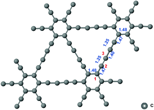
The network structure of graphynes could be regarded as the C6 hexagons in graphene interconnected by acetylene linkages, which possessed a special atomic arrangement and an electronic structure.21 The two adjacent sp2-hybridized carbon atoms in graphdiyne were connected by two “–CΞC–” linkages.22 The model of graphdiyne and the bond length of the structure after structural optimization are shown Fig. 1. It could be observed that the bond length in the benzene ring was around 1.48 Å. The bond lengths in “–CΞC–” linkages and the bond linked to the benzene ring were 1.25 Å and 1.47 Å, respectively. Moreover, the two “–CΞC–” linkages were connected by a carbon–carbon bond with a bond length of 1.40 Å. The bond length is the essential criteria for the bonding type. When compared with the standard bond length in the benzene ring of 1.39 Å, the benzene ring in graphdiyne was slightly elongated to 1.48 Å. Similarly, the length of the triple bond in acetylene was 1.20 Å; therefore, the triple bond in the “–CΞC–” linkage was also elongated to 1.25 Å. It is interesting to note that the bond between the “–CΞC–” linkage and the benzene ring exhibited a length of 1.47 Å, which was similar to the C![[double bond, length as m-dash]](https://www.rsc.org/images/entities/char_e001.gif) C bond length in the benzene ring, indicating that a conjugated structure was formed. The two “–CΞC–” linkages were connected by a bond of length 1.40 Å, which was shorter than a length of 1.47 Å exhibited by the bond between the “–CΞC–” linkage and the benzene ring. Considering the symmetry of the structure, the three carbon atoms are denoted as sites 1, 2, and 3, as shown in Fig. 1. The hybridization of site 1 could be regarded as sp2. Moreover, the hybridization of site 2 is between sp2 and sp (sp–sp2), which was conjugated with the adjacent benzene ring. Site 3 was the one with sp hybridization. Next, we investigated the free energy diagram of CO2RR on the sites 1, 2, and 3.
C bond length in the benzene ring, indicating that a conjugated structure was formed. The two “–CΞC–” linkages were connected by a bond of length 1.40 Å, which was shorter than a length of 1.47 Å exhibited by the bond between the “–CΞC–” linkage and the benzene ring. Considering the symmetry of the structure, the three carbon atoms are denoted as sites 1, 2, and 3, as shown in Fig. 1. The hybridization of site 1 could be regarded as sp2. Moreover, the hybridization of site 2 is between sp2 and sp (sp–sp2), which was conjugated with the adjacent benzene ring. Site 3 was the one with sp hybridization. Next, we investigated the free energy diagram of CO2RR on the sites 1, 2, and 3.
CO2RR pathway on graphdiyne
For CO2RR, the two-electron reduction products are CO and HCOOH. As shown in eqn (1) and (2), the initial protonation of CO2 leads to the generation of either *COOH or *HCOH, which can be further reduced to *CO or *HCOOH, respectively. Subsequently, *CO and *HCOOH can be desorbed from the catalyst as CO and HCOOH products, respectively.| CO2 → *COOH → *CO → CO | (1) |
| CO2 → *OCOH → *HCOOH → HCOOH | (2) |
However, if the adsorbed *CO is further reduced to *CHO or *COH, CH3OH and CH4 are available as the six-electron or eight-electron reduction products, respectively.
 | (3) |
 | (4) |
| *CHO/*COH → *CHOH → *CH2OH → CH3OH | (5) |
It should be noted that CH4 can be generated via two routes, as shown in eqn (3) and (4). In eqn (3), *CHO or *COH is first reduced to *CHOH, which can be further protonated to *CH and H2O. Then, *CH is further reduced to CH4 in a series of protonation steps. However, as shown below, the step of *CHOH → *CH always involves a high energy barrier compared with *OCH3, which indicates that the pathway in eqn (3) is inferior to that in eqn (4) on graphdiyne. On the other hand, as shown in eqn (4), *CHO is reduced to *OCH2 and further reduced to *OCH3 and again to *OCH4. Next, *OCH4 is reduced to *OH and CH4 product, which is released from the surface. For CH3OH, eqn (5) shows the following pathway: *CHO is first reduced to *CHOH, and *CHOH is further reduced to *CH2OH, which in turn is reduced to CH3OH as the final product. The graphical illustration of the pathways is shown in Fig. S1.†
Herein, the computational hydrogen electrode (CHE) model pioneered by Nørskov et al. was applied to depict the free energy diagram of CO2RR, which accounted for the energy of a proton–electron pair (H+ + e−) in an aqueous solution.26 The reaction free energy of each elementary reaction −ΔG is calculated as follows:
| ΔG = μ[product] − μ[reactant] − 0.5μ[H2(g)] + eU |
Specifically, when U = 0 V,
| ΔG = −UL × e |
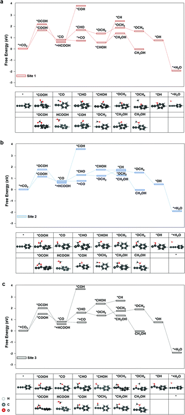
The diagrams of the reaction free energies are plotted in Fig. 2(a)–(c), for sites 1, 2 and 3, respectively. It can be clearly seen that the hydrogenation of CO2 to form the carboxyl group (*COOH) is more favourable than that of the formate group (*OCOH). It is noted that *OCHO binds to the active site via one of the two oxygen atoms, while *COOH binds via the carbon atom.27 The subsequent reduction of *COOH generates *CO, which could either desorb as CO or undergo a further reduction to form *CHO or *COH, which is the key intermediate for CH3OH and CH4 products.28 On the other side, the reduction of *OCHO led to the formation of HCOOH, which readily desorbed from the surface of graphdiyne.29 For CO and HCOOH, the formation of *COOH or *OCOH is the step with the highest reaction energy barrier. It is indicated that the first hydrogenation step of CO2 is the potential-determining step. On sites 1, 2 and 3, the energy barriers of *COOH formation were 1.52 eV, 1.12 eV, and 1.30 eV, respectively. Therefore, the limiting potentials (UL) for the CO product are −1.52 V, −1.12 V, and −1.30 V, on sites 1, 2, and 3, respectively. For HCOOH, the UL values were −2.14 V, −1.82 V, and −1.98 V, on sites 1, 2, and 3, respectively. The site 2 on graphdiyne with sp2–sp hybridization exhibits the lowest limiting potential of −1.12 V for the CO product.
As mentioned above, for CH3OH and CH4 products, the key intermediate *CHO or *COH is generated from the *CO reduction. This step is crucial for CH3OH and CH4 products on numerous catalysts.30,31 On graphdiyne, the formation of *CHO is much more favourable than *COH on all three sites. On sites 1, 2 and 3, the free energy changes from *CO to *CHO were 1.04 eV, 0.64 eV, and 0.89 eV, respectively, while the free energy of *COH were 3.84 eV, 3.45 eV, and 3.53 eV, respectively, much higher than that of *CHO. It could be seen that site 2 exhibits the lowest energy barrier for *CO → *CHO. As shown in eqn (3) and (4), for the CH4 product, the step of *CHOH → *CH2OH is more favourable than the step of *CHOH → *CH on the three sites. Therefore, the pathway of the CH4 product is more likely to occur viaeqn (4). Subsequently, the steps following the formation of *CHO are relatively easy with low energy barriers. Starting from *CHO, on site 1, the step with the largest energy barrier is *CHOH → *CH2OH with 0.62 eV for CH3OH, and for CH4, the step with the largest energy barrier is *OCH2 → *OCH3 with 0.48 eV. Similarly, on site 2, for CH3OH and CH4 products, the counterparts are *CHO → *CHOH (0.34 eV) and *OCH2 → *OCH3 (0.33 eV), respectively. On site 3, for CH3OH and CH4 products, the counterparts are *CHO → *CHOH (0.50 eV) and *OCH2 → *OCH3 (0.40 eV), respectively. Therefore, starting from *CO for CH3OH and CH4 products, the potential-determining step is *CO → *CHO, and the limiting potentials are −1.04 V, −0.64 V, and −0.89 V on sites 1, 2, and 3, respectively. Site 2 is the most active site for both the CH3OH and CH4 products. After applying a potential of −1.12 V (UL for *COOH formation at site 2), the free energy diagram at site 2 is shown in Fig. S2.† At this potential, the free energies of all the intermediates and products moved towards a negative direction. Except for the HCOOH product that still exhibited an energy barrier of 0.7 V, the CO, CH3OH and CH4 products demonstrated a downhill energy diagram, indicating that these products are viable at −1.12 V.
The major difference among sites 1, 2, and 3 is hybridization. As shown in Fig. S3,† the Bader charge analysis shows that the site 2 changes the hybridization from sp–sp2 to sp2, forming a stable conjugated structure with the neighbouring benzene ring, which is beneficial for the charge redistribution. For further insight into the hybridization effect on activity, we investigated the free energy diagram of CO2RR on graphene, which is purely composed of sp2 carbon atoms. As shown in Fig. 3, the free energy diagram clearly shows that the step of CO2 → *COOH is the one with the largest energy barrier (2.34 eV) on graphene. Compared with that on graphdiyne, the free energy barrier on graphene is much more difficult to overcome. The enormously high energy barrier on graphene could be attributed to the stable network with the sp2 hybridized carbon atom, which is detrimental to the activity. On the contrary, a pristine graphdiyne exhibited a high activity towards CO2RR. The comparison between the graphene and graphdiyne illustrated the key role of hybridization on the activity of carbon catalysts. The sp–sp2 hybridization in graphdiyne is beneficial for the first reduction step of CO2 → *COOH and *CO → *CHO, which are the key steps for CO2RR.
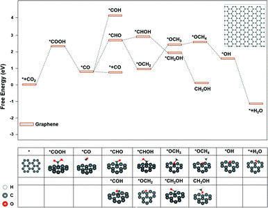 | ||
| Fig. 3 The free energy diagram of CO2RR on graphene. Noted that *OCOH could not form a stable adsorption structure on graphene. Inset: The graphene model used for the calculations. | ||
The effect of nitrogen doping
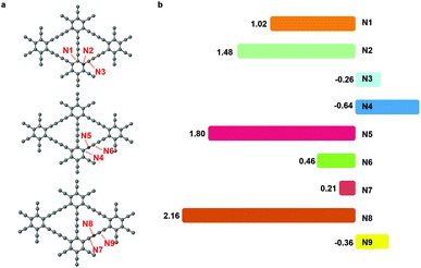
The nitrogen doping has been recognized as an effective way to improve the electrochemical performance of carbon materials.32,33 The nitrogen dopant induced an alteration in the electronic structure of the catalyst surface, which facilitated the adsorption of intermediates and the electron transfer.34 In CO2RR, nitrogen had been successfully introduced into the carbon catalysts, leading to a higher activity and selectivity.35,36 Herein, we substituted site 1, site 2 or site 3 carbon atom in graphdiyne with a nitrogen atom.As shown in Fig. 4(a), the nitrogen atom and two neighbouring sites are denoted as N1 to N9 and are investigated as the active sites for CO2RR. We could learn from pristine graphdiyne that the first step of CO2 → *COOH is pivotal, which remarkably influenced the overall pathway of CO2RR. Therefore, we focused on the formation energy of *COOH to screen the catalytic activity of sites N1 to N9. As shown in Fig. 4(b), it can be clearly seen that the free energy of *COOH formation varies significantly on different sites. Notably, N1, N3, N4, N6, N7 and N9 exhibited a low reaction energies of 1.02 eV, −0.26 eV, −0.64 eV, 0.46 eV, 0.21 eV, and −0.36 eV, respectively, for the *COOH formation. Compared with the pristine graphdiyne, the introduction of nitrogen atom is effective in reducing the energy barrier of the *COOH formation.
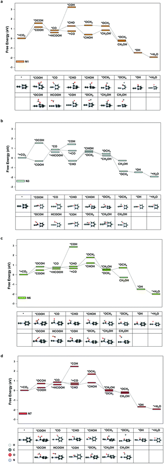
We further investigated the free energy change along the pathway of CO2RR on these sites. N3, N4, and N9 exhibited a negative free energy change for the *COOH formation, but further calculations showed that N4 and N9 exhibited a high energy barrier for *COOH → *CO of 1.30 eV and 1.68 eV, respectively, while N3 demonstrated a moderate barrier of 0.91 eV. Therefore, we studied the reaction energy profiles of CO2RR on N1, N3, N6 and N7. As shown in Fig. 5, it can be seen that on N1, the formation of *COOH or *OCOH is the step with the highest energy barriers of 1.02 eV and 1.62 eV, respectively, which is similar to that on the pristine graphdiyne. Next, *OCOH was reduced to HCOOH and desorbed from the catalyst, while *COOH was reduced to *CO. Subsequently, *CO could be either desorbed from the surface or reduced to *CHO/*COH and then further reduced to CH3OH or CH4. It was noted that compared with *CHO, the *COH formation was much more difficult with a high free energy barrier on N1, N6 and N7. The largest energy barriers from *CO to CH3OH or CH4 were 0.65 eV and 0.01 eV in the step of *CHOH → *CH2OH and *CHO → *OCH2, respectively. Therefore, the CH4 product was more favourable than that of CH3OH on N1.
As for N3, it was interesting to note that the formation of *COOH exhibited a favourable energy change of −0.26 eV, which indicated a strong adsorption of *COOH on N3. From the *COOH configuration in Fig. 5(b), it can be observed that the distance between the carbon atom on the N3 site and the adjacent nitrogen atom is elongated so that a vacancy is formed, in which the *COOH intermediate is trapped. However, the step of *COOH → *CO exhibited a high energy barrier of 0.91 eV. Subsequently, the energy barriers of *CO → *CHOH and *CO → *OCH2 are 1.07 eV and 1.03 eV, respectively, which indicated that CH3OH and CH4 were less likely to generate than the CO product. Therefore, it was observed that the CO production was more dominant on N3.
As shown in Fig. 5(c) and (d), on N6 and N7, the energy barriers of the *COOH formation are 0.46 eV and 0.21 eV, respectively. Hence, the formation of *COOH is not the step with the largest energy barrier on N7. Instead, the step of *COOH → *CO exhibited high energy barriers of 0.60 eV. In the following steps, compared with that of the pristine graphdiyne and N1, the energy barrier of *CO → *CHO was significantly reduced, which was beneficial for the CH3OH and CH4 products. Starting from *CO, the largest energy barriers for CH3OH and CH4 products were 0.26 eV and 0.98 eV on N6, respectively, while the counterparts on N7 were 0.02 eV and 1.00 eV, respectively. It was clearly seen that the CH4 production was impeded by the sluggish step of *CHO → *OCH2, while the steps towards the CH3OH product was greatly facilitated on N6 and N7. Fig. S4† shows the free energy diagram of CO2RR on N1, N3, N6, and N7 at applied potentials of −1.02 V, −0.91 V, −0.46 V and −0.60 V, respectively. It could be seen that on N6, the pathway to CH3OH was energetically favourable at a low potential of −0.46 V. Nitrogen-doping not only improved the activity of CO2RR by reducing the energy barrier of the *COOH formation, but also enhanced the selectivity towards CH4 on N1, CO on N3, and CH3OH on N6 and N7, respectively. N6 exhibited the lowest limiting potential of −0.46 V for the CH3OH product. It indicated that the nitrogen-doped graphdiyne possessed a high activity and selectivity towards CH3OH, a valued liquid fuel, which was reportedly only produced on metal catalysts, such as Cu-based catalysts and cobalt phthalocyanine in literature.37–39
The nitrogen defects and hydrogen evolution reaction
It has been reported that the nitrogen-defects are crucial for the CO2RR activity.15,16,19 Herein, the pyrrolic and pyridinic nitrogen defects were constructed on graphdiyne to investigate the activity of nitrogen defects. As shown in Fig. S6,† the first hydrogenation step is more favoured towards *COOH instead of *OCOH on both the nitrogen defects. Subsequently, it is interesting to note that the adsorption of *CO is stable on the pyrrolic nitrogen, and the following hydrogenation step of *CO → *CHO was energetically easier in occurrence than the desorption of *CO. On the other hand, on the pyridinic nitrogen *CO is readily desorbed from the catalyst. The primary reduction product on the pyrrolic nitrogen is CH3OH, and the highest energy barrier is 1.29 eV on the step of *CH2OH → *CH3OH. On the pyridinic nitrogen, CO is the primary product with the highest energy barrier of 0.96 eV on the step of *COOH → *CO. It could be seen that on comparison with the pyrrolic nitrogen the pyridinic nitrogen is more active and favourable for the CO product. This is consistent with previous studies on the nitrogen-doped carbon catalysts for CO2RR.40–42The hydrogen evolution reaction (HER) is a competitive reaction for CO2RR, which should be avoided. The free energy of *H adsorption is studied on sites 1, 2, 3, and N1–N9. As shown in Fig. S7,† the results indicate that the adsorption energy of *H is relatively more negative than the formation of *COOH, as shown in Fig. 2 and 5, except for N3 site, which indicates that H* adsorption is strong on these sites. On the N3 site, the free energy change of CO2 → *COOH is −0.26 eV, while the *H adsorption energy is 0.02 eV. Thus, the N3 site is selective towards CO2RR against HER. The results implied that HER could be a concerning issue for the practical usage of the graphdiyne catalyst for CO2RR. Nonetheless, it should be noted that in recent experimental studies on CO2RR, numerous methods were employed to suppress HER effectively, such as ionic liquids,43 aqueous pH buffer regions,44 cations,45 and nitrogen co-catalysts.46 In particular, the flow cell equipped with a gas diffusion electrode allowed the alkaline electrolyte use to suppress HER, which significantly enhanced the faradaic efficiency of CO2RR products.47–49 Using these methods, some metals, such as Pd, which were theoretically inclined to produce H2, exhibited a high faradaic efficiency for CO2RR.50,51 Therefore, by taking cautious approaches, the parasitic HER on graphdiyne could be dealt with in CO2RR experiments.
The electronic structures: effects of hybridization and doping
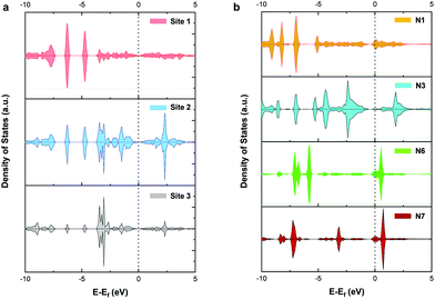
To further explore the mechanism of CO2RR on pristine and nitrogen-doped graphdiyne, we studied the partial density of states (PDOS) of the carbon 2p orbital in sites 1, 2, and 3 of pristine graphdiyne and N1, N3, N6, and N7 in nitrogen-doped graphdiyne. It was reported that the stronger states near the Fermi level indicated a better capacity for the electron-transfer, therefore facilitating the catalytic activity. As shown in Fig. 6(a), on site 1 and site 3 of pristine graphdiyne, the states near the Fermi level are relatively low. Compared with site 1 and site 3, site 2 showed higher states near the Fermi level. As discussed in the energy diagram of CO2RR, the formation of *COOH is much easier on site 2 compared with that on site 1 and site 3. Similarly, in the nitrogen-doped graphdiyne, the states near the Fermi level were much higher in N6 and N7 than that observed in N1 and N3, which were consistent with the low energy barrier of *CO → *CHO on N6 and N7. The favourable energy change of the formation of *COOH and *CHO on N3 could be attributed to the elongation between the active site and the adjacent carbon atom, which led to a vacancy accommodating the intermediate. As shown in Fig. S6,† the charge density difference of the *COOH adsorption on pristine and nitrogen-doped graphdiyne shows that the site 2 in pristine graphdiyne, along with N6 and N7 in the nitrogen-doped graphdiyne, exhibits a significant alteration in the charge density of the catalyst, with a noticeable hybridized conjugation on the active site and adjacent atoms. Moreover, as mentioned above, the Bader analysis indicated that the lower free energy barrier for the *COOH formation was closely related to the hybridization transition of the sp–sp2 to sp2. The PDOS and charge analysis suggested that site 2, N6 and N7 possessed a better capability of charge transfers, which explained the lower energy barrier of the *COOH and *CHO formations on these sites.Conclusion
Using the DFT calculations, the activity and selectivity of graphdiyne towards CO2RR were evaluated, and the effect of carbon hybridization was also thoroughly investigated. The results showed that the site 2 with sp2–sp hybridization exhibited the best activity with a low activation barrier for the CO, CH3OH and CH4 products. Compared with graphene with pure sp2 hybridization that showed a much higher energy barrier for CO2RR, the sp2–sp hybridization with the conjugated structure was crucial for the CO2RR activity over graphdiyne. Nitrogen doping was found to be effective for improving the CO2RR activity. The electronic structure analysis demonstrates that the strong adsorption of key intermediate *COOH/*CHO could be attributed to the increased density of states near the Fermi level and the conjugated charge redistribution facilitated the sp2–sp to sp2 transition, leading to a stronger adsorption of the intermediates. The current study predicts a good application prospect of graphdiyne for CO2RR, and the new insight into the relationship between hybridization and reactivity sheds light on further development of the carbon catalysts for CO2RR.Conflicts of interest
The authors declare no competing financial interest.Acknowledgements
We gratefully acknowledge the financial support from the National Natural Science Foundation of China (grant no. 22002158 and 21403023), the National Scientific Fund of Liaoning Province (grant no. 20180510035), and the Dalian National Laboratory for Clean Energy (grant no. DNL180404 and DNL201924). G. X. Wang thanks the financial support from the CAS Youth Innovation Promotion (grant no. Y201938). T. F. Liu thanks the fellowship of China Postdoctoral Science Foundation (grant no. 2019M661142).Notes and references
- S. Zhang, Q. Fan, R. Xia and T. J. Meyer, Acc. Chem. Res., 2020, 53, 255–264 CrossRef PubMed
.
- S. Nitopi, E. Bertheussen, S. B. Scott, X. Liu, A. K. Engstfeld, S. Horch, B. Seger, I. E. L. Stephens, K. Chan, C. Hahn, J. K. Nørskov, T. F. Jaramillo and I. Chorkendorff, Chem. Rev., 2019, 119, 7610–7672 CrossRef CAS PubMed
.
- D. H. Nam, P. De Luna, A. Rosas-Hernandez, A. Thevenon, F. Li, T. Agapie, J. C. Peters, O. Shekhah, M. Eddaoudi and E. H. Sargent, Nat. Mater., 2020, 19, 266–276 CrossRef PubMed
.
- Y. Wu, Z. Jiang, X. Lu, Y. Liang and H. Wang, Nature, 2019, 575, 639–642 CrossRef PubMed
.
- W. Ma, S. Xie, T. Liu, Q. Fan, J. Ye, F. Sun, Z. Jiang, Q. Zhang, J. Cheng and Y. Wang, Nat. Catal., 2020, 3, 478–487 CrossRef
.
- K. Ye, A. Cao, J. Shao, G. Wang, R. Si, N. Ta, J. Xiao and G. Wang, Sci. Bull., 2020, 9, 711–719 CrossRef
.
- D. Gao, H. Zhou, J. Wang, S. Miao, F. Yang, G. Wang, J. Wang and X. Bao, J. Am. Chem. Soc., 2015, 137, 4288–4291 CrossRef CAS PubMed
.
- B. Pan, X. Zhu, Y. Wu, T. Liu, X. Bi, K. Feng, N. Han, J. Zhong, J. Lu, Y. Li and Y. Li, Adv. Sci., 2020, 7, 2001002 CrossRef PubMed
.
- D. Yang, L. Liu, Q. Zhang, Y. Shi, Y. Zhou, C. Liu, F. Wang and X. Xia, Sci. Bull., 2020, 65, 796–802 CrossRef
.
- P. Zhu and H. Wang, Sci. Bull., 2020, 65, 977–979 CrossRef CAS
.
- W. Li, M. Seredych, E. Rodríguez-Castellón and T. J. Bandosz, ChemSusChem, 2016, 9, 606–616 CrossRef CAS PubMed
.
- A. Vasileff, Y. Zheng and S. Z. Qiao, Adv. Energy Mater., 2017, 7, 1700759 CrossRef
.
- S. Chen, T. Liu, S. O. Olanrele, Z. Lian, C. Si, Z. Chen and B. Li, J. Energy Chem., 2021, 54, 143–150 CrossRef
.
- N. Sreekanth, M. A. Nazrulla, T. V. Vineesh, K. Sailaja and K. L. Phani, Chem. Commun., 2015, 51, 16061–16064 RSC
.
- H. Wang, Y. Chen, X. Hou, C. Ma and T. Tan, Green Chem., 2016, 18, 3250–3256 RSC
.
- Y. Liu, S. Chen, X. Quan and H. Yu, J. Am. Chem. Soc., 2015, 137, 11631–11636 CrossRef CAS PubMed
.
- T. Liu, S. Ali, Z. Lian, C. Si, D. S. Su and B. Li, J. Mater. Chem. A, 2018, 6, 19998–20004 RSC
.
- K. Nakata, T. Ozaki, C. Terashima, A. Fujishima and Y. Einaga, Angew. Chem., Int. Ed., 2014, 53, 871–874 CrossRef CAS
.
- X. Duan, J. Xu, Z. Wei, J. Ma, S. Guo, S. Wang, H. Liu and S. Dou, Adv. Mater., 2017, 29, 1701784 CrossRef
.
- G. Li, Y. Li, H. Liu, Y. Guo, Y. Li and D. Zhu, Chem. Commun., 2010, 46, 3256–3258 RSC
.
- C. Huang, Y. Li, N. Wang, Y. Xue, Z. Zuo, H. Liu and Y. Li, Chem. Rev., 2018, 118, 7744–7803 CrossRef CAS PubMed
.
- X. Gao, H. Liu, D. Wang and J. Zhang, Chem. Soc. Rev., 2019, 48, 908–936 RSC
.
- Y. Zhao, J. Wan, H. Yao, L. Zhang, K. Lin, L. Wang, N. Yang, D. Liu, L. Song, J. Zhu, L. Gu, L. Liu, H. Zhao, Y. Li and D. Wang, Nat. Chem., 2018, 10, 924–931 CrossRef CAS PubMed
.
- L. Yang, J. Shui, L. Du, Y. Shao, J. Liu, L. Dai and Z. Hu, Adv. Mater., 2019, 31, e1804799 CrossRef PubMed
.
- L. Hui, Y. Xue, H. Yu, Y. Liu, Y. Fang, C. Xing, B. Huang and Y. Li, J. Am. Chem. Soc., 2019, 141, 10677–10683 CrossRef CAS PubMed
.
- A. A. Peterson, F. Abild-Pedersen, F. Studt, J. Rossmeisl and J. K. Nørskov, Energy Environ. Sci., 2010, 3, 1311 RSC
.
- S. Back, J. Lim, N. Y. Kim, Y. H. Kim and Y. Jung, Chem. Sci., 2017, 8, 1090–1096 RSC
.
- S. Back and Y. Jung, ACS Energy Lett., 2017, 2, 969–975 CrossRef CAS
.
- J. T. Feaster, C. Shi, E. R. Cave, T. Hatsukade, D. N. Abram, K. P. Kuhl, C. Hahn, J. K. Nørskov and T. F. Jaramillo, ACS Catal., 2017, 7, 4822–4827 CrossRef CAS
.
- S. Wang, J. Wang and H. Xin, Green Energy Environ., 2017, 2, 168–171 CrossRef
.
- T. Liu, S. Ali, Z. Lian, B. Li and D. S. Su, J. Mater. Chem. A, 2017, 5, 21596–21603 RSC
.
- C. Chen, X. Sun, X. Yan, Y. Wu, H. Liu, Q. Zhu, B. B. A. Bediako and B. Han, Angew. Chem., 2020, 59, 11123–11129 CrossRef CAS
.
- T. Ma, Q. Fan, X. Li, J. Qiu, T. Wu and Z. Sun, J. CO2 Util., 2019, 30, 168–182 CrossRef CAS
.
- G. Li, Y. Qin, Y. Wu, L. Pei, Q. Hu, H. Yang, Q. Zhang, J. Liu and C. He, Chin. J. Catal., 2020, 41, 830–838 CrossRef CAS
.
- H. Wang, J. Jia, P. Song, Q. Wang, D. Li, S. Min, C. Qian, L. Wang, Y. F. Li, C. Ma, T. Wu, J. Yuan, M. Antonietti and G. A. Ozin, Angew. Chem., Int. Ed., 2017, 27, 7955–7960 CrossRef
.
- Y. Song, W. Chen, C. Zhao, S. Li, W. Wei and Y. Sun, Angew. Chem., Int. Ed., 2017, 36, 10980–10984 CrossRef
.
- J. Albo and A. Irabien, J. Catal., 2016, 343, 232–239 CrossRef CAS
.
- W. Zhang, Q. Qin, L. Dai, R. Qin, X. Zhao, X. Chen, D. Ou, J. Chen, T. Chuong, B. Wu and N. Zheng, Angew. Chem., Int. Ed., 2018, 57, 9475–9479 CrossRef CAS
.
- Y. Wu, Z. Jiang, X. Lu, Y. Liang and H. Wang, Nature, 2019, 575, 639–642 CrossRef CAS
.
- J. Wu, R. M. Yadav, M. Liu, P. P. Sharma, C. S. Tiwary, L. Ma, X. Zou, X. Zhou, B. I. Yakobson, J. Lou and P. M. Ajayan, ACS Nano, 2015, 9, 5364–5371 CrossRef CAS
.
- H. Wang, Y. Chen, X. Hou, C. Ma and T. Tan, Green Chem., 2016, 18, 3250–3256 RSC
.
- S. Liu, H. Yang, X. Huang, L. Liu, W. Cai, J. Gao, X. Li, T. Zhang, Y. Huang and B. Liu, Adv. Funct. Mater., 2018, 28, 1800499 CrossRef
.
- B. A. Rosen, A. Salehi-Khojin, M. R. Thorson, W. Zhu, D. T. Whipple, P. J. A. Kenis and R. I. Masel, Science, 2011, 334, 643–644 CrossRef CAS PubMed
.
- C. Delacourt, P. L. Ridgway, J. B. Kerr and J. Newman, J. Electrochem. Soc., 2008, 155, B42–B49 CrossRef CAS
.
- M. R. Thorson, K. I. Siil and P. J. A. Kenis, J. Electrochem. Soc., 2013, 160, F69–F74 CrossRef CAS
.
- C. E. Tornow, M. R. Thorson, S. Ma, A. A. Gewirth and P. J. A. Kenis, J. Am. Chem. Soc., 2012, 134, 19520–19523 CrossRef CAS
.
- Q. Gong, P. Ding, M. Xu, X. Zhu, M. Wang, J. Deng, Q. Ma, N. Han, Y. Zhu, J. Lu, Z. Feng, Y. Li, W. Zhou and Y. Li, Nat. Commun., 2019, 10, 2087 CrossRef
.
- X. Lu, Y. Wu, X. Yuan, L. Huang, Z. Wu, J. Xuan, Y. Wang and H. Wang, ACS Energy Lett., 2018, 3, 2527–2532 CrossRef CAS
.
- K. Ye, Z. Zhou, J. Shao, L. Lin, D. Gao, N. Ta, R. Si, G. Wang and X. Bao, Angew. Chem., 2020, 59, 4814–4821 CrossRef CAS PubMed
.
- D. Gao, H. Zhou, F. Cai, J. Wang, G. Wang and X. Bao, ACS Catal., 2018, 8, 1510–1519 CrossRef CAS
.
- B. M. Tackett, J. H. Lee and J. G. Chen, Acc. Chem. Res., 2020, 53, 1535–1544 CrossRef CAS PubMed
.
Footnote |
| † Electronic supplementary information (ESI) available. See DOI: 10.1039/d0gc03742g |
| This journal is © The Royal Society of Chemistry 2021 |

