Synthetic self-propelled nanorotors†
Sébastien
Fournier-Bidoz
,
André C.
Arsenault
,
Ian
Manners
* and
Geoffrey A.
Ozin
*
Materials and Polymer Research Groups, Department of Chemistry, University of Toronto, 80 St. George Street, Toronto, Ontario, Canada M5S 3H6. E-mail: imanners@chem.utoronto.ca; gozin@chem.utoronto.ca
First published on 29th November 2004
Abstract
Self-powered completely synthetic nanorotors have been prepared from barcoded gold–nickel nanorods having the gold end anchored to the surface of a silicon wafer; constant velocity circular movements are observed when hydrogen peroxide fuel is catalytically decomposed to oxygen at the unattached nickel end of the nanorod.
A hallmark of nanoscience is its interdisciplinarity, encompassing chemistry and physics, materials science and engineering, biology and medicine. Within each discipline diverse nanotechnologies are anticipated to emerge with a particular commonality, namely a power generator that will provide the energy needed to accomplish a particular task. Two radically distinct approaches to the practical realization of such power sources are being investigated: a top-down macroscopic power source connected to a nanoscale device or machine via interconnects1 and a bottom-up nanoscopic power source such as a nanobattery, nanofuel or nanosolar cell integrated into the nanoscale device or machine. Because Nature is the master builder of a myriad of nanoscopic power sources and machines a contemporary endeavor is to discover how they work and to use this knowledge to create artificial analogues that could spawn new nanotechnologies.
In the context of tiny artificial machines, biomolecular motors have been used to power nanodevices, and lasers have been utilized to drive microrotors.2,3 These little machines respectively use ATP and light as sources of power. Nanoscale fuel cells are also being actively investigated however practical examples have yet to be demonstrated. Whitesides and coworkers,4 recently showed the autonomous movement of millimetre sized objects in water that were powered by an on-board oxygen generator based upon the platinum metal catalyzed decomposition of hydrogen peroxide. In this report we describe our preliminary observations for a purely synthetic self-propelled nanorotor, tethered at one end to the surface of a silicon wafer and revolving at a constant speed, believed to be the first synthetic example of a nanoscale rotary machine powered by H2O2.
To amplify, our nanomachine comprises a barcoded bimetal nanorod in which one segment is made of nickel and functions as a catalyst for the decomposition of H2O2. During the decomposition, oxygen is produced at the surface of the nickel segment according to the reaction 2H2O2(l) = O2(g) + 2H2O(l) and provides the driving force for nanorod propulsion. The other segment can be made of any material that is not reactive towards hydrogen peroxide, such as an inorganic, organic or polymeric metal, semiconductor or insulator; in the case described herein the other segment was made of gold.
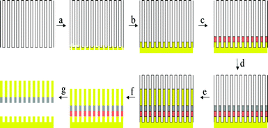
The synthesis of barcoded bimetal nanorods was carried out using the technique developed by Natan et al.,5 which is based on the use of a nanochannel alumina membrane as a template to cast electrodeposited metal within the nanoscale channels of the membrane into rod shapes. Both commercial and homemade6 alumina membranes can be used. The barcoded bimetal nanorods were grown by electrochemical deposition of the desired metal with a pre-determined segment length inside the channels of such membranes as illustrated in Fig. 1. First, 100 nm of gold was sputtered onto the alumina membrane (Fig. 1a), followed by electrodeposition of gold to plug any remaining pores and create a solid electrode (Fig. 1b). Then a sacrificial copper segment was electrodeposited (Fig. 1c), followed by a nickel segment (Fig. 1d) and finally a gold one (Fig. 1e). The nanorods so formed were released from the template by dissolution of the alumina in 3 M sodium hydroxide solution (Fig. 1f) followed by the removal of the sacrificial layer of copper in an ammoniacal solution of hydrogen peroxide (Fig. 1g). The nanorods were then subjected to multiple centrifugation and washing steps with de-ionized water to remove any residual ionic species from the aqueous dispersion. In the experiments to be described, nanorods with 2 μm long gold and 500 nm long nickel segments were used. A few microlitres of the aqueous nanorod suspension were injected into a custom-made cell and their motional dynamics recorded in the presence and absence of hydrogen peroxide using a BX41 Olympus microscope equipped with a Pixelink firewire CCD camera. The base of the observation cell was a silicon wafer.
 | ||
| Fig. 1 Schematic of nanobarcode synthesis. (a) Gold sputtering onto an alumina membrane. (b) Electrodeposition of gold plugs. (c) Electrodeposition of a sacrificial layer of copper. (d) Electrodeposition of nickel segment. (e) Electrodeposition of gold segment. (f) Selective dissolution of alumina. (g) Selective dissolution of copper. | ||
Upon addition of H2O2 to the nanorod suspension, oxygen evolution is observed arising from the catalytic decomposition of H2O2 on the Ni part of the nanorods. Nanorods in suspension start migrating along the direction of liquid flow generated by the injection of the H2O2 fuel. By contrast, nanorods that touch and anchor to the surface of the silicon wafer do not migrate—instead they rotate.
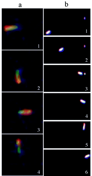
Two types of nanorod rotational dynamics are observed. The first rotational motion, available as a supplementary movie,† resembles the movement of the arm of a clock (Fig. 2a). This occurs when the gold end of a nanorod becomes anchored to the silicon substrate while having the nickel end revolving freely in solution. We believe that the tethering process is favoured either by adventitious impurities or defects present on the silicon substrate that have a size roughly the diameter of a nanorod, that is about 200 nm. In support of this assumption, one can observe in Fig. 2b selected frames that illustrate the migration of a nanorod towards an impurity site on the silicon surface. It can be seen that after tethering to this site the nanorod begins circumscribing a circular motion. Both clockwise and counterclockwise rotations have been observed and we believe that a particular rotation sense is favoured by the flow direction of the solvent and/or imperfections on the nanorod surface. Interestingly, the revolution speed of the nanorotors is clocked to be fairly constant and equal to 1.5 ± 0.2 rad s−1. The nanorod rotation comes to a halt when the supply of hydrogen peroxide has been depleted, however upon reinstating the fuel supply the nanorod starts to rotate again.
 | ||
| Fig. 2 (a) Optical microscope snapshots of a nanorod rotating counterclockwise. (b) Optical microscope snapshots showing the dynamics of a suspended nanorod with a near-linear movement followed by tethering to a surface impurity that induces a circular movement. | ||
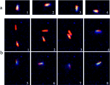
The second dynamic behaviour as seen in Fig. 3a, also available in supplementary movies,† can be described as an autonomous movement around a circular orbit having an approximate diameter of 2.5 μm. While its origin is still not certain, it could be explained by a slight structural asymmetry of the nanorod that generates more oxygen thrust on one side. Such asymmetry could be responsible for the observed circular orbiting motion instead of the straight-line propulsion mentioned earlier. For this particular gyratory dynamic behaviour, a nanorod is observed to accomplish a single rotation in 3 s.
 | ||
| Fig. 3 (a) Optical microscope snapshots of a tethered nanorod undergoing clockwise rotation. (b) Optical microscope snapshots of a suspended nanorod and its tethering to a surface impurity that induces its rotation. | ||
As several hundred nanorods are present in solution, collisions between nanorods are expected to occur. From such collisions, also available as a supplementary movie,† an interesting phenomenon has been observed (Fig. 3b). While a nanorod is rotating clockwise, a collision may occur with another nanorod and the resulting nanorod pair undergoes an abrupt change of direction and starts rotating counterclockwise. Such a change in direction is likely to be due to the vectorial sum of propulsion forces acting on each nanorod. Further work is underway to study such event.
In summary, completely synthetic self-propelled nanorotors have been described based on silicon wafer-tethered barcoded bimetal nanorods. Several kinds of rotational behaviour with constant speed have been noted. Preliminary studies indicate that by varying the concentration of hydrogen peroxide as well as the length of the nickel segment, it is possible to control the angular velocity of the rotating nanorods. Nanorods devoid of the nickel segment or starved of fuel do not exhibit the dynamic effects described in this paper. Investigations directed towards a better understanding of nanorod tethering and positioning, substrate effects, dynamic nanorod diagnostics, rotation speed and rotation direction are in progress, knowledge of which will assist in the development of single or multiple arrays of designed architecture on-chip nanorod and crossed nanorod rotational actuators, switches, valves and power sources for nanoscale electronic, optical, magnetic, mechanical and fluidic dynamic devices.
We thank the Canadian Government for a Canada Research Chair in Materials Chemistry (2001–2008, G. A. O.), and Inorganic and Polymer Chemistry (2001–2008, I. M.). I. M. also thanks the Ontario Government for a PREA award (1999–2004).
Notes and references
- A. M. Fennimore, T. D. Yuzvinsky, W.-Q. Han, M. S. Fuhrer, J. Cumings and A. Zettl, Nature, 2003, 424, 408 CrossRef CAS.
- R. K. Soong, G. D. Bachand, H. P. Neves, A. G. Olkhovets, H. G. Craighead and C. D. Montemagno, Science, 2000, 290, 1555 CrossRef CAS.
- E. Higurashi, R. Sawada and T. Ito, Appl. Phys. Lett., 1998, 72, 2951 CrossRef CAS; P. Galajda and P. Ormos, Appl. Phys. Lett., 2001, 78, 249 CrossRef CAS; T. Harada and K. Yoshikawa, Appl. Phys. Lett., 2002, 81, 4850 CrossRef CAS; V. Bingelyte, J. Leach, J. Courtial and M. J. Padgett, Appl. Phys. Lett., 2003, 82, 829 CrossRef CAS; K. Miyakawa, H. Adachi and Y. Inoue, Appl. Phys. Lett., 2004, 84, 5440 CrossRef CAS.
- R. F. Ismagilov, A. Schwartz, N. Bowden and G. M Whitesides, Angew. Chem., Int. Ed., 2002, 41, 652 CrossRef CAS.
- S. R. Nicewarner-Pena, R. G. Freeman, B. D. Reiss, L. He, D. J. Pena, I. D. Walton, R. Cromer, C. D. Keating and M. J. Natan, Science, 2001, 294, 137 CrossRef CAS.
- S. Fournier-Bidoz, V. Kitaev, D. Routkevitch, I. Manners and G. A. Ozin, Adv. Mater., 2004 Search PubMed , web early view.
- Note added in proof: at the time our paper was submitted to Chemical Communications, Mallouk and coworkers reported in the Journal of the American Chemical Society that catalytic nanorods with different compositions could undergo linear-type motions in solution. W. F. Paxton, K. C. Kistler, C. C. Olmeda, A. Sen, S. K. St. Angelo, Y. Cao, T. E. Mallouk, P. E. Lammert and V. H. Crespi, J. Am. Chem. Soc., 2004, 126, 13424 Search PubMed.
Footnote |
| † Electronic supplementary information (ESI) available: 3 real-time videos representing the dynamic behaviour illustrated as snapshots in this communication are available as supporting information. See http://www.rsc.org/suppdata/cc/b4/b414896g/ |
| This journal is © The Royal Society of Chemistry 2005 |
