
 Open Access Article
 This Open Access Article is licensed under a
 Creative Commons Attribution 3.0 Unported Licence
Effects of sulfate modification of stoichiometric and lithium-rich LiNiO2 cathode materials†
Bo
Dong
 *ad,
Andrey D.
Poletayev
bd,
Jonathon P.
Cottom
bdgh,
Javier
Castells-Gil
ad,
Ben F.
Spencer
e,
Cheng
Li
f,
Pengcheng
Zhu
cd,
Yongxiu
Chen
cd,
Jaime-Marie
Price
ad,
Laura L.
Driscoll
ad,
Phoebe K.
Allan
ad,
Emma
Kendrick
cd,
M. Saiful
Islam
*bdg and
Peter R.
Slater
*ad
*ad,
Andrey D.
Poletayev
bd,
Jonathon P.
Cottom
bdgh,
Javier
Castells-Gil
ad,
Ben F.
Spencer
e,
Cheng
Li
f,
Pengcheng
Zhu
cd,
Yongxiu
Chen
cd,
Jaime-Marie
Price
ad,
Laura L.
Driscoll
ad,
Phoebe K.
Allan
ad,
Emma
Kendrick
cd,
M. Saiful
Islam
*bdg and
Peter R.
Slater
*ad
aSchool of Chemistry, University of Birmingham, Birmingham B15 2TT, UK. E-mail: b.dong@bham.ac.uk; p.r.slater@bham.ac.uk
bDepartment of Materials, University of Oxford, Oxford, OX1 3PH, UK. E-mail: Saiful.islam@materials.ox.ac.uk
cSchool of Metallurgy and Materials, University of Birmingham, Birmingham B15 2TT, UK
dThe Faraday Institution, Harwell Science and Innovation Campus, Didcot OX11 0RA, UK
eDepartment of Materials and Henry Royce Institute, The University of Manchester, Oxford Road, Manchester, M13 9PL, UK
fNeutron Sciences Directorate, Spallation Neutron Source (SNS), Oak Ridge National Laboratory, 37830, TN, USA
gDepartment of Chemistry, University of Bath, Bath, BA2 7AY, UK
hLeiden Institute of Chemistry, Gorlaeus Laboratories, Leiden University, 2300 RA Leiden, The Netherlands
First published on 4th April 2024
Abstract
Lithium nickel oxide, LiNiO2, has attracted considerable interest as a high energy cathode for next generation lithium-ion batteries. Nevertheless, shortcomings such as significant cycling capacity decay and low stability in ambient atmosphere have hindered its practical application, and consequently most work has focused on the more stable Mn and Co doped analogues Li(Ni,Mn,Co)O2. Here, we report an investigation of an alternative strategy, sulfate modification, in the LiNiO2 system. We show that improved performance can be achieved, attributed to the dual effect of a low level of bulk doping and the presence of a self-passivation Li2SO4 layer formed beyond the solid solution limit. Ab initio simulations suggest that the behavior is similar to that of other high valent dopants such as W and Mo. These dual effects contribute to the improved air stability and enhanced electrochemical performance for the sulfate modified lithium-rich LiNiO2, leading to high initial capacities (∼245 mA h g−1 at 25 mA g−1, and ∼205 mA h g−1 at 100 mA g−1) and better capacity retention. Overall, the results show that polyanion modification represents an excellent alternative low-cost strategy to improve the performance of lithium nickel oxide cathode materials.
1. Introduction
Lithium-ion batteries (LIBs) dominate the energy storage market for portable electronics and electrical vehicles (EVs) due to their high energy densities.1–4 Ni-rich lithium transition metal oxides, such as LiNixCoyAl1−x−yO2 (NCA) and LiNixMnyCo1−x−yO2 (NMC) have attracted great interest and are extensively applied in the field.5–7 However, the high and volatile cost of Co hinders their long-term sustainability and motivates research into higher Ni content, lower Co content NMC (NMC811, LiNi0.8Mn0.1Co0.1O2) materials. Ultimately a key aim is to eliminate Co to give LiNiO2 (LNO), which is considered as the promising next generation cathode due to its high theoretical capacity of ∼270 mA h g−1 and high average voltage of 3.8 V vs. Li metal.8,9However, the intrinsic problems with this stoichiometric LNO phase, such as moisture instability at ambient atmosphere, detrimental phase transitions and particle cracking at high states of charge remain unresolved.10,11 During delithiation, several phase transitions of Li1−xNiO2 occur during the charging process, which includes hexagonal (H1, 0 ≤ x ≤ 0.25) to monoclinic (M, 0.25 ≤ x ≤ 0.55), monoclinic (M) to hexagonal (H2, 0.55 ≤ x ≤ 0.75), and hexagonal (H2) to hexagonal (H3, 0.75 ≤ x ≤ 1).12–15 In particular, the H2–H3 phase transition of Li1−xNiO2 above 4.1 V triggers the shrinkage of the unit cell and large volume change due to the large difference of c parameters of H2 (c = 14.404(1) Å) and H3 (c = 13.363(6) Å) phases.16,17 The resulting microcracks of active cathode material leads to further side reactions of cathode and electrolyte, which accelerates the capacity fade of LiNiO2.18 To mitigate these issues, most attempts have focused on dopant incorporation and surface modification to stabilise the material.19–22
It has been demonstrated that Ti or Zr doped LiNiO2 have limited solid solution ranges, with a small amount of dopant incorporation into the bulk structure and with the remaining dopant forming surface layers (such as Li2TiO3 and Li2ZrO3) on the LiNiO2 particles.23,24 In other work, Al or Mg doping of LiNiO2 was found to dramatically reduce the amount of residual surface lithium carbonate in ambient atmosphere owing to strong TM(Al/Mg)–O bonding, which inhibits the reaction between water/carbon dioxide and LiNiO2.25–27 High-valence dopants, such as W and Mo, have also been examined in LiNiO2.28–32In situ XRD results have indicated that W doped LiNiO2 modified the H2–H3 phase transition into a more gradual solid solution reaction during cycling, and the resulting enhancement of cycling stability was attributed to an alleviation of the structural stress and abrupt lattice changes.28
All these previous studies have involved doping with cations of similar octahedral size to Ni. As an alternative to such cation incorporation, polyanion doping is a less widely used strategy in altering the structural, chemical or physical properties of inorganic materials. This methodology has attracted much interest in perovskite oxide electrodes for solid oxide fuel cells, where results illustrate that transition-metal octahedra TMO6 can be replaced with tetrahedral MO4 (M = Si, S, P) or trigonal planar MO3 (C, B) to create materials with improved properties.33–41
In this work, we examine the effect of sulfate modification in LiNiO2 and Li-rich LiNiO2, and the corresponding effect on the structural and electrochemical properties using a combined experimental and modelling approach. The formation of Li-rich phases with Ni-rich compositions has been challenging so far, producing poorly ordered materials. The aim of polyanion doping was also to introduce tetrahedral ions with higher charge and oxygen vacancies in order to help to stabilise a Li-rich phase that is otherwise challenging to isolate.42 Our results show enhanced electrochemical performance on sulfate incorporation compared to undoped materials prepared under comparable conditions.
2. Results and discussion
2.1 Phase formation and crystal structures
 | ||
| Fig. 1 XRD patterns of LiNiO2 and S doped LiNiO2 (solid state synthesis route). | ||
| Composition | a = b (Å) | c (Å) | V (Å3) |
|---|---|---|---|
| LiNiO2 | 2.8814(1) | 14.2079(1) | 102.16(2) |
| LiNi0.975S0.025O2−x | 2.8817(1) | 14.2155(1) | 102.23(2) |
| Composition | I 003/I104 |
|---|---|
| LiNiO2 | 1.569 |
| LiNi0.975S0.025O2−x | 2.834 |
Following these initial results and given that the doping was expected to lower the anion content (total anion charge), and the dopant (normally S6+) has a higher charge than Ni, the possible stabilisation of higher Li content/lower Ni content phases was investigated. Sulfate doped Li-rich LiNiO2 (S-LRNO) were made under similar conditions used for LNO to increase the capacity. As shown in Fig. 2a (XRD data), the S-free control Li1.1Ni0.85O2 shows a majority layered phase with unknown impurity peaks at lower two theta angles. In contrast, when adding a small amount of sulfate, Li1.1Ni0.875S0.025O2−δ shows a single-phase sample, indicating the benefits of sulfate in stabilising the phase formation. A small amount of Li2SO4 impurity was detected with increasing sulfate content (Li1.1Ni0.85S0.05O2−δ), suggesting only a low-level incorporation of sulfate in the Li-rich LiNiO2 system. The presence of a small amount of bulk sulfate and a surface Li2SO4 layer for this sample is supported by the XPS/HAXPES data (see later).
 | ||
| Fig. 2 (a) XRD patterns of Li1.1Ni0.85O2, Li1.1Ni0.875S0.025O2−x and Li1.1Ni0.85S0.05O2−x (solid state synthesis route). (b) Observed, calculated and difference profiles from structural refinement of Li1.1Ni0.85S0.05O2−δ using neutron diffraction data (c) XAS data of Li1.1Ni0.85S0.05O2−x. | ||
Structural refinement of Li1.1Ni0.85S0.05O2−δ using neutron diffraction data was performed, with the profile fits shown in Fig. 2b. Weight fractions of Li2SO4, Li2CO3 and Li1.1Ni0.85S0.05O2−δ were refined to give 95.9% S-LRNO, 2.0% Li2SO4 and 2.1% Li2CO3, which is consistent to XRD results. 0.03 S was then added to the Li2/Ni2 site (Ni layer), and constraints of the same Uiso and full occupancy were made for Li1/Ni1; and Li2/Ni2/S1. The atomic position of O1 was refined followed by Uisos of all atoms which were fixed after convergency. The occupancies of Li1/Ni1, Li2/Ni2 (to give the occupancy of S1) and O1 were refined. A final refinement of the Uiso of all atoms showed only a small change and the final parameters are shown in Table 3. From these data, the refined composition was determined to be Li1.047(3)Ni0.922(3)S0.031O1.98(2), consistent with the formation of a higher Li content/lower Ni content phase.
| Atom | x | y | z | Mult. | Occupancy | U iso (Å2) |
|---|---|---|---|---|---|---|
a Space group: R![[3 with combining macron]](https://www.rsc.org/images/entities/char_0033_0304.gif) mh, a = b = 2.8777(1) Å, c = 14.1938(1) Å, V = 101.79(1) Å3. mh, a = b = 2.8777(1) Å, c = 14.1938(1) Å, V = 101.79(1) Å3.
|
||||||
| Li1 | 0 | 0 | 0 | 3 | 0.978(2) | 0.016 |
| Ni1 | 0 | 0 | 0 | 3 | 0.022(2) | 0.016 |
| S1 | 0 | 0 | 0.5 | 3 | 0.031 | 0.002 |
| Li2 | 0 | 0 | 0.5 | 3 | 0.069(1) | 0.002 |
| Ni2 | 0 | 0 | 0.5 | 3 | 0.900(1) | 0.002 |
| O1 | 0 | 0 | 0.242(1) | 6 | 0.992(4) | 0.011 |
In support of sulfate doping, the Ni K-edge XAS also indicates a small shift for the sulfate doped sample, where the normalised absorption of S-LRNO is shifted to lower energy compared to that of LiNiO2 (Fig. 2c). The slight shift of the Ni K-edge for S-LRNO suggests the partial reduction of Ni3+ in the bulk material. In order to evaluate the surface states, XPS data were collected. Here, the Ni 2p spectrum (Fig. S1†) is dominated by the spin–orbit doublet characterized by binding energies of the Ni 2p3/2 and Ni 2p1/2 core levels of 855.2 and 872.6 eV, respectively. The spectra also show broad satellites at 862.7 and 879.2 eV. All of these binding energy values are representative of the nickel environments in LiNiO2.43,44
HAXPES and XPS spectra were collected to investigate the presence of S dopant in the bulk and on the surface of S-LNRO, respectively. XPS and HAXPES spectra of S 2p of S-LRNO are shown in Fig. 3a and b. The S 2p signal is a spin–orbit doublet and each chemical state consists of two peaks. The S 2p (XPS) can be fitted with two components at ∼169.2 eV and ∼170.5 eV, corresponding to a metal sulfate, here attributed to Li2SO4.45 The HAXPES did not show the S 2p response but the signal from S 1s was detected. Two components at ∼2477.9 eV and ∼2480.0 eV can be used to fit S 1s spectra. However, since 1s core levels are singlet states, the two peaks in the S 1s peak suggest more than one chemical state, which may be related to sulfate in a different environment to surface Li2SO4 (i.e. bulk incorporation).
 | ||
| Fig. 3 XPS and HAXPES spectra of S-LRNO (solid state route). (a) XPS spectra of S 2p, (b) HAXPES spectra of S 1s, (c) XPS spectra of O 1s, and (d) HAXPES spectra of O 1s. | ||
The recorded O 1s spectra from XPS and HAXPES are shown in Fig. 3c and d. The O 1s spectra (XPS) are fitted to two oxygen contributions at ∼528.9 eV and ∼531.8 eV, and the O 1s spectra (HAXPES) are fitted to three components at ∼528.4 eV, ∼531.4 eV and ∼533.9 eV. The components at ∼528 eV and ∼531 eV are assigned to metal–oxygen bonds and carbonate groups, respectively.46,47 The O 1s contribution above ∼533 eV can be assigned to either water or sulfate bonds (both are located in this region).48 Previous studies of sulfate incorporation into perovskite oxides have indicated associated oxygen vacancies are introduced.33 The refinement of the structure for S-LRNO, however, reveals only a very small amount of oxygen vacancies in this case. Computational modelling (below) also suggests that generating oxygen vacancies within the layered structure is a high-energy, i.e., unfavorable process. Hence, given that the amount of oxygen vacancies appears to be very low, their presence is difficult to detect by either XPS or HAXPES.
The chemical stability in ambient atmosphere of polyanion modified LNO was examined by exposing both undoped and sulfate doped samples to air. The XRD results, as shown in Fig. 4a, shows a clear degradation in the undoped LNO sample with the detection of additional peaks at ∼36 and ∼44° after exposing to air for 2 weeks (zoomed-in region is shown in Fig. S2†). In contrast, sulfate modified LRNO showed no change under the same conditions (Fig. 4b), illustrating the improved stability in ambient atmosphere of this phase.
 | ||
| Fig. 4 XRD patterns of (a) LiNiO2 and (b) Li1.1Ni0.85S0.05O2−δ (solid state route) after the exposure in air after 1, 15 and 30 days. | ||
At the conditions of synthesis (700 °C, 1 atm O2) where layered LNO is in equilibrium with disordered rocksalt from which it is synthesized, the lowest-energy incorporation of dilute LiNi defects into the disproportionated structure is 0.30 eV (Table 4), which decreases with the supplied Li excess (increase in μLi).42,50 The logical limit of such excess Li incorporation is Li2NiO3, where LiNi defects fully substitute one of three Ni sub-lattices, and all remaining Ni atoms have zero spin and are formally in a “4+” charge state. However, experimental attempts have only approached this limit with substantial Ni disorder and reduction;26 layered Li2NiO3 has to our knowledge not been synthesized.
| Defect | Incorporation energy (eV) | Compensation |
|---|---|---|
| LiNi | 0.30 | hNi |
| VO | 1.40 | eNi |
| NiLi49 | −0.12 | eNi |
Turning to sulfate doping, the predicted lowest-energy site for the bulk incorporation of dilute S is SNi at 2.92 eV during synthesis (Table 5). The dopant SNi is surrounded and compensated by additional high-spin nickels, which approximate Ni2+. Such compensation additionally relieves the mechanical stress created by extremely short S–O bonds (≈1.69 Å) of the SNi by surrounding it with enlarged Ni octahedra. We find it further instructive to compare the energetics of incorporation of sulfur with other common high-valence dopants such as W and Mo, which are known to phase-separate at interfaces and grain boundaries.31,32 The incorporation energies for MoNi and WNi are both under 1 eV, and the dopant–oxygen bond lengths are much closer to those of the parent nickel octahedra at 1.93 Å.
| Dopant | Incorporation energy (eV) | Chemical potential (eV) | Reference phase | Bond length (Å) |
|---|---|---|---|---|
| MoNi | 0.84 | −6.29 | Li4MoO5 (ref. 31) | 1.93 |
| WNi | 0.91 | −7.16 | Li4WO5 | 1.93 |
| SNi | 2.92 | −4.52 | Li2SO4 | 1.69 |
| SNi,(104) | 6.93 | −4.52 | Li2SO4 | 1.59 |
| SNi,(012) | 4.57 | −4.52 | Li2SO4 | 1.57 |
| SNi,(100) | 4.56 | −4.52 | Li2SO4 | 1.59 |
| SNi,(110) | 4.96 | −4.52 | Li2SO4 | 1.57 |
The association of SNi with oxygen vacancies (formation energy 1.40 eV on their own) is not favorable: the loss of coordination by the surrounding nickel offsets the favorability of approaching tetrahedral S, with an association energy of 0.85 eV (Table 6). This contrasts with polyanion doping of perovskites, where each oxygen anion is two-coordinate, and fewer metal–oxygen bonds are broken to accommodate the sulphur. The association of excess LiNi with SNi is only favorable by 20 meV (Table 6); such an effect does not translate to finite temperatures when the octahedra are dynamically disordered. Surface incorporation at Ni sites has similarly unfavorable energetics (Table 5), although the figures are approximate due to the multitude of possibilities for compensation via polarons, O, and Li.
| Complex | Association energy (eV) |
|---|---|
| Li–Ni exchange | −0.05 |
| SNi + LiNi | −0.02 |
| SNi + NiLi | 0.20 |
| SNi + Li–Ni exchange | 0.23 |
| SNi + VO | 0.85 |
However, since Li2SO4 forms a eutectic with Li2CO3,51 its addition can facilitate lithiation and crystallisation during the solid state synthesis of LNO at the experimental temperatures used here, which are below the melting point of Li2CO3. This positive effect is demonstrated by a small decrease in the full width at half maximum of XRD peaks in the sulfate modified sample prepared using the solid state route, as shown in Fig. S3.†
2.2 Electrochemical performance
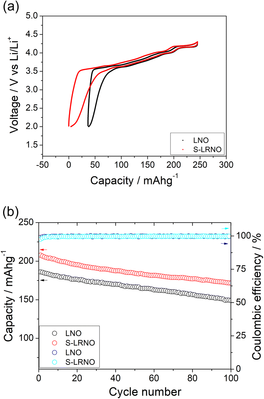
 | ||
| Fig. 5 (a) Initial charge–discharge curves of LNO and S-LRNO synthesised by the solid state method between 2 and 4.3 V at 25 mA g−1 (after the formation cycle). (b) The cycling performance of LNO and S-LRNO at 25 mA g−1. | ||
To confirm the importance of sulfate incorporation in addition to surface coating, a separate experiment to introduce Li2SO4 as a coating was examined. Here the Li1.1Ni0.85O2 was ball milled (500 rpm/1 h) with 5% Li2SO4 which is the equivalent sulfate content in the structure (sample named as coated-LRNO), and reheated at 700 °C/12 h in O2. As shown in Fig. 6a, the XRD pattern of ball milled Li1.1Ni0.85O2 (with Li2SO4) showed a layered phase with Li2SO4 impurity and a few unknown peaks. The electrochemical performance of Li1.1Ni0.85O2 (LRNO) and the 5% Li2SO4 coated Li1.1Ni0.85O2 (coated-LRNO) was examined using the same conditions to that of S-LRNO. As shown in Fig. 6b, both LRNO and coated-LRNO showed poorer performance compared to that of S-LRNO, indicating the sulfate incorporation assisted with the formation of the lithium-excess phase. In addition, while the discharge capacities of coated-LRNO improved a little compared to LRNO, the values are much lower than S-LRNO (Fig. 6b and S6†), which further supports the successful sulfate incorporation in the original sample. The improved electrochemical performance could result from both the limited sulfate dopant in the structure and the Li2SO4 passivating layers which is spontaneously formed beyond the solid solution limitation, in addition to the Li2SO4–Li2CO3 eutectic effects facilitating high lithiation and crystallization in the solid state synthesis (as mentioned in the modelling section).
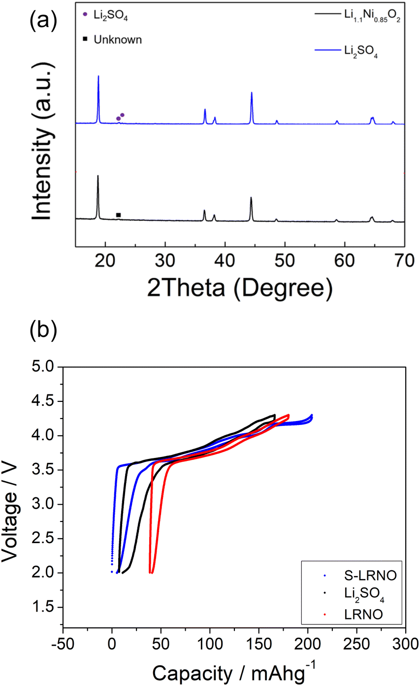 | ||
| Fig. 6 (a) XRD patterns of Li1.1Ni0.85O2−x, and Li2SO4 ball milled Li1.1Ni0.85O2−x. (b) Charge–discharge curves of solid state route synthesised LRNO, S-LRNO and LRNO with 5%Li2SO4 between 2 and 4.3 V at 25 mA g−1 (after the formation cycle). | ||
 | ||
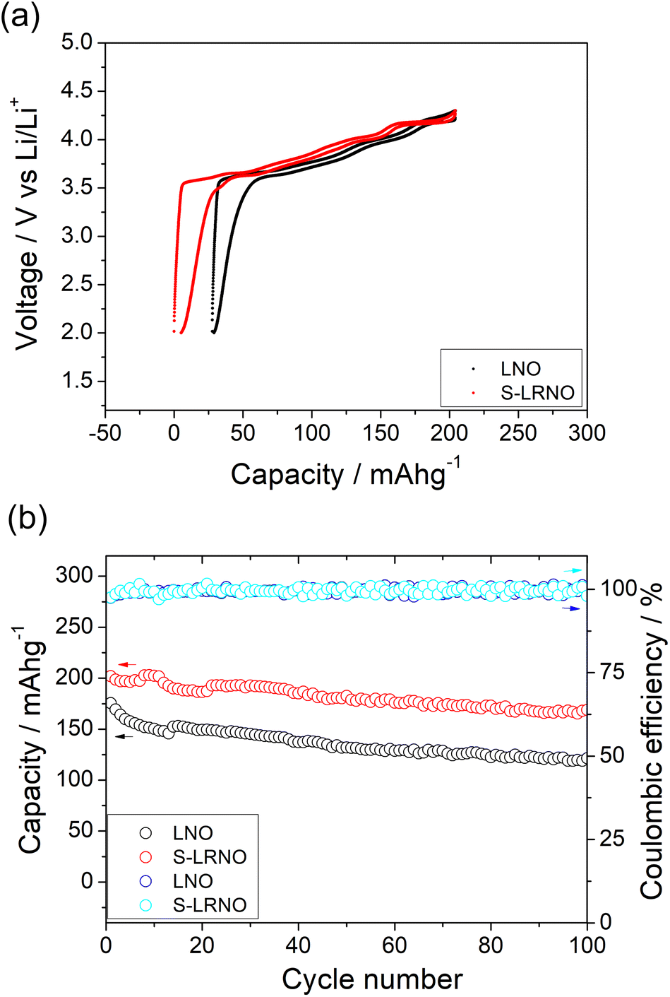
| Fig. 7 (a) Initial charge–discharge curves LNO and S-LRNO synthesised by the co-precipitation route between 2 and 4.3 V at 25 mA g−1 (after the formation cycle). (b) The cycling performance of LNO and S-LRNO at 100 mA g−1. | ||
Rate capabilities of co-precipitated LNO and S-LRNO were then tested in the voltage range of 2.0–4.3 V at current densities of 25, 50, 100, 200, 400 and 25 mA g−1 for 5 cycles (Fig. 8a). The discharge capacities of co-precipitated S-LRNO and LNO reached 230 and 209 mA h g−1 at 25 mA g−1, 207 and 176 mA h g−1 at 50 mA g−1, 192 and 165 mA h g−1 at 100 mA g−1, 176 and 145 mA h g−1 at 200 mA g−1, 161 and 117 mA h g−1 at 400 mA g−1 respectively. The S-LRNO sample exhibits higher discharge capacities than those of the pristine LNO at all cycling rates, illustrating the improved rate capability of the sulfate modified sample.
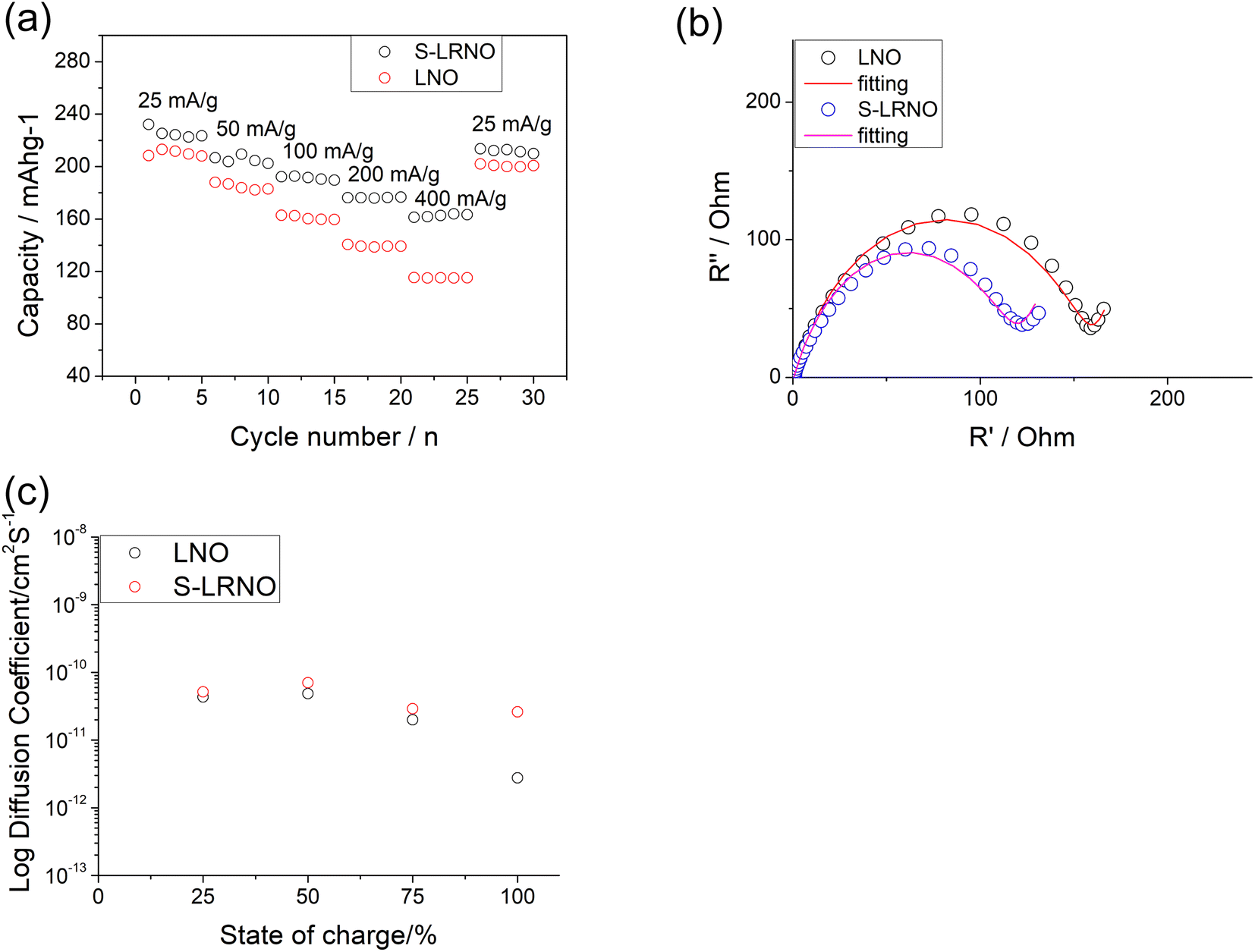 | ||
| Fig. 8 (a) The cycling performance of LNO and S-LRNO prepared using co-precipitation route at different rates. (b) EIS of LNO and S-LRNO prepared using co-precipitation route at the 1st cycle. (c) GITT of LNO and S-LRNO prepared using co-precipitation route on charging at the initial cycle (after formation cycles). | ||
Electrochemical impedance spectroscopy analysis for both samples are shown in Fig. 8b. The smaller semicircle was seen in S-LRNO than that of LNO, indicating a smaller internal resistance. By fitting the Nyquist plots with the equivalent circuit, the S-LRNO shows a charge transfer resistance of 119 Ω which is lower than 160 Ω in LNO (Table 7). To investigate the influence of sulfate modification on the kinetic behavior of Li+, GITT (galvanostatic intermittent titration technique) was carried out to determine the apparent diffusion capability of Li+ in the initial cycle (after formation cycles). The DLi calculated from the GITT curve as a function of the state of charge during charging are shown in Fig. 8c, where the measured solid-state diffusion coefficient is mainly in the range of 10−12 to 10−11. The sulfate doped sample exhibits an increased DLi value compared to LNO, indicating faster kinetics for Li ion in the doped sample. Although the SEM analyses of LNO and S-LRNO prepared using the co-precipitation route revealed comparable morphology of particles (Fig. 9), the observed enhancements in rate capability and lithium transport kinetics in S-LRNO could be attributed to the excess lithium ions in the structure; this feature helps to promote the formation of face-sharing or edge-sharing lithium octahedra, leading to reduced lithium ion hopping distance and lower activation energy.
| Parameter | LNO | S-LRNO |
|---|---|---|
| R 1 (Ω) | 1.5 | 1.4 |
| R CT (Ω) | 160 | 119 |
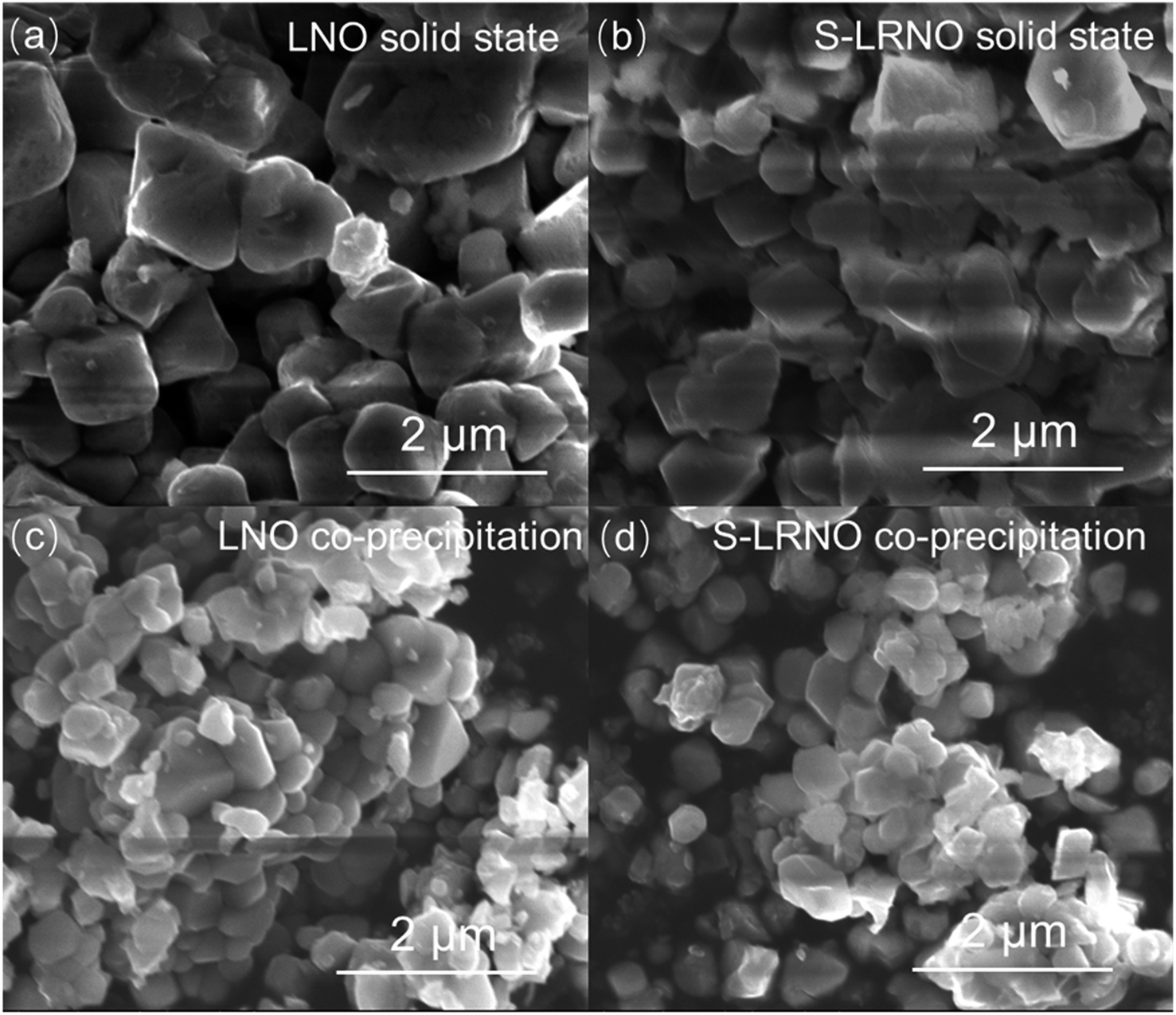 | ||
Fig. 9 SEM images of samples at 50![[thin space (1/6-em)]](https://www.rsc.org/images/entities/char_2009.gif) 000× magnification (a) LNO prepared by solid state route (b) S-LRNO prepared by solid state route (c) LNO prepared by co-precipitation route (d) S-LRNO prepared by co-precipitation route. 000× magnification (a) LNO prepared by solid state route (b) S-LRNO prepared by solid state route (c) LNO prepared by co-precipitation route (d) S-LRNO prepared by co-precipitation route. | ||
The structural transitions during the cycling of doped and undoped LRNO prepared using co-precipitation routes was evaluated using dQ/dV curves, as shown in Fig. 10; H1–M, M–H2, and H2–H3 phase transitions were observed for both materials, which is consistent with literature.11 In contrast to the quickly decaying H2–H3 phase transition in undoped LNO, this transition has been preserved after long-term cycling for sulfate doped samples, as shown in Fig. 9d. This result suggests that structural changes during the cycling for the sulfate modified phase are more reversible, which most likely accounts for the improved long-term capacity. In this respect, it has been reported that high valence dopants, such as Mo6+ and W6+, in LiNiO2, could facilitate the merging of the Li-rich and Li-poor phases into a single phase during the H2–H3 phase transition, resulting in better structural stability.28,31 Other studies have shown that high valence dopants help to suppress primary particle growth during synthesis and impart mechanical toughness to counteract the high internal strain.32,52 The introduction of excess Zr4+ into the LiNiO2 cathode was shown to result in simultaneous doping and coating with Li2ZrO3, enhancing the phase transition and thermal stability,23 similar to what we observe for sulfate doping (small incorporation with Li2SO4 coating). The SEM images of S-LRNO and LNO before and after 200 cycles are shown in Fig. 11, where cracking was observed for LNO whereas S-LRNO showed better particle preservation, illustrating further the benefits of sulfate modification.
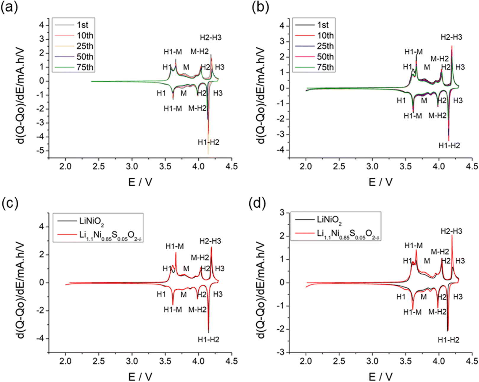 | ||
| Fig. 10 dQ/dV curves of (a) LiNiO2 and (b) Li1.1Ni0.85S0.05O2−x prepared through co-precipitation route; (c) comparison of LiNiO2 and Li1.1Ni0.85S0.05O2−x at 1st cycle. (d) Comparison of LiNiO2 and Li1.1Ni0.85S0.05O2−x at 75th cycle showing the clear preservation of H2–H3 transition in the latter. | ||
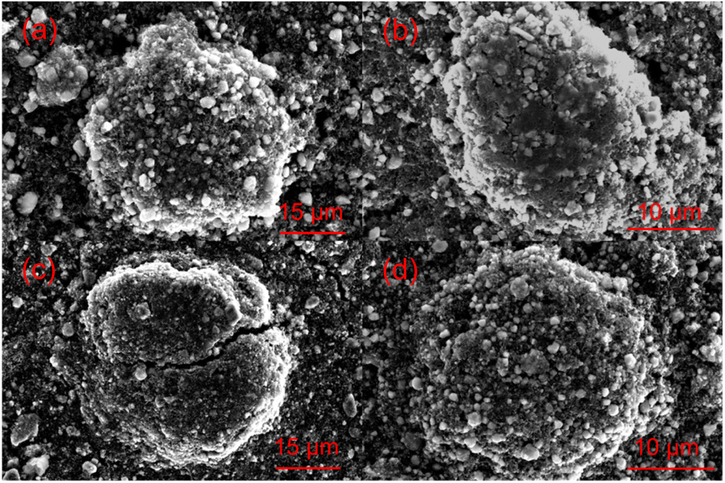 | ||
| Fig. 11 SEM images of (a) pristine LiNiO2; (b) pristine Li1.1Ni0.85S0.05O2−x (c) LiNiO2 after 200 cycles. (d) Li1.1Ni0.85S0.05O2−x after 200 cycles. | ||
3. Conclusions
Polyanion (sulfate) modified LiNiO2 and Li-rich LiNiO2 were synthesised through solid state and co-precipitation methods. Although the solid solution of sulfate doping appears to be limited in line with modelling results, a self-passivation Li2SO4 layer formed beyond the solid solution, which contributed to the improvement in air stability and to the electrochemical performance of sulfate modified Li-rich LiNiO2 (S-LRNO).Such improved electrochemical performance as well as better capacity retention for S-LRNO was observed for samples prepared using both solid state and co-precipitation methods. The initial 245 mA h g−1 discharge capacity (at 25 mA g−1) for co-precipitation synthesised S-LRNO represents a significant improvement to conventional Mn and Co co-doped NMC systems. High capacities were also observed at higher rates (205 mA h g−1 initial discharged capacity at 100 mA g−1), with improved capacity retention compared to the unmodified system and attributed to the improved preservation of the H2–H3 transition. Overall, this work highlights that as an alternative design strategy, polyanion modification can effectively improve the electrochemical properties of lithium nickel oxide cathode materials, which has the potential to be easily applied to other cathode systems.
4. Experimental
4.1 Synthesis
For the solid state synthesis method, Li2CO3 (99.9%, Alfa Aesar), Ni(NO3)2·6H2O (%, Sigma-Aldrich), (NH4)2SO4·H2O (99%, Sigma-Aldrich), (NH4)H2PO4 (99%, Sigma-Aldrich) and SiO2 (99%, Sigma-Aldrich) were used as reagents. Li1+zNi1−z−xMxO2−y (M = S, P, Si) samples from intimately ground stoichiometric amounts of starting reagents were heated initially to 650 °C for 12 hours at a rate of 2.5 °C min−1 to fully decompose starting reagents. A 2.5% excess Li2CO3 was added to the mixture to compensate for Li loss during the synthesis. The mixture was milled (ZrO2 containers and balls) with hexane solvent for 30 minutes using a Pulverisette 5 planetary ball mill to yield fine powders. The powders were pressed into pellets and reheated one or multiple times at 700–725 °C for 12 hours in dry O2 with a rate of 5 °C min−1 to obtain the final product, which is stored in an Ar-filled glove box.For co-precipitation method, Ni(OH)2 precursor were synthesised by precipitation from an aqueous solution of Ni(NO3)2·6H2O and NaOH. Then (NH4)2SO4·H2O (99%, Sigma-Aldrich), Ni(OH)2 (as prepared) and LiOH·H2O (99%, Sigma-Aldrich) were mixed with 5–10% excess LiOH·H2O by ball milling in a zirconia pot at 500 rpm for 1 hour. The mixture was heated to 350 °C for 12 hours at 2.5 °C min−1 and followed by heating to 700 °C for 12 hours at 5 °C min−1 in O2 to obtain the final product. The sample was allowed to cool down to room temperature and stored in an Ar-filled glove box.
4.2 X-ray diffraction
A Bruker D8 X-ray diffractometer (XRD) with CuKα radiation and linear position sensitive detector was used to collect X-ray diffraction data. Patterns were recorded over the 2θ range 15° to 80° with a 0.02° step size. Structural refinement was carried out using the XRD data with the GSAS suite of Rietveld refinement software.534.3 Neutron diffraction
The neutron diffraction experiment was performed on the POWGEN instrument at the Spallation Neutron Source (SNS), Oak Ridge National Laboratory. Approximately 1 g of powder was loaded into a PAC vanadium can with 6 mm diameter. The sample cans were loaded into POWGEN sample changer (PAC) and the diffraction data was collected at 293 K for around 2 hour, followed by the standard data reduction routine. The center wavelength was 0.8 Å, covering a d spacing range of 6.2 Å > d > 0.1 Å.4.4 Electrochemical testing
The active materials and carbon black (TimCal, C65) were dried at 110 °C for 24 h in a vacuum oven before use. The slurry was prepared by mixing 80% active materials, 10% carbon black and 10% polyvinylidene fluoride (PVDF, PI-KEM) in N-methyl-2-pyrrolidine (NMP, Sigma) using a Thinky mixer, before coating onto an aluminum foil in a dry room. The cathode was dried at 120 °C for 24 h in the vacuum oven and punched into 14.8 mm disks. The electrode disks were weighed and the mass loading of active materials on cathodes was 3–4 mg cm−2. Li metal (Aldrich) was used as anode, which was rolled and punched into 15 mm disks. The composition of the electrolyte (R&D 281, Soulbrain) was 1.0 M LiPF6 in EC:EMC (ethylene carbonate/methyl carbonate, 3/7 V/V) with 1 wt% VC (vinylene carbonate) as an electrolyte additive. Microporous trilayer membrane (PP/PE/PP) (H1609, Celgard) was used as the separator.
The half cells using the components above were assembled with CR2032 coin cells in an argon-filled glove box and all electrochemical measurements were conducted on the BCS805 cell tester (Bio-logic). Galvanostatic charge/discharge with potential limitation (GVPL) measurement was conducted at constant current density of 25 mA g−1, 50 mA g−1 or 100 mA g−1 in the voltage range between 2 and 4.3 V vs. Li/Li+. Electrochemical impedance spectroscopy (EIS) measurement was performed in half-cell using an amplitude of 5 mV in the frequency range from 10−2 to 105 Hz. For the data analysis, EC-Lab software was used for the equivalent circuit models fitting.
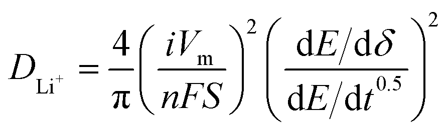
For galvanostatic intermittent titration technique (GITT) measurement, the cells were charged and discharged at 25 mA g−1 with a rest (3 h) to achieve full equilibrium voltage. Fundamental ideas calculating diffusion coefficients from GITT technique have originated from the research work by Weppner and Huggins.54 Here we adopted the transformed sand equation to calculate the diffusion of Li+ in the active particle materials from the following eqn (1).
 | (1) |
The rate tests for LNO and S-LRNO prepared using co-precipitation routes were performed in hall cells using different current densities at 25, 50, 100, 200, 400 mA g−1 within the voltage window of 2 to 4.3 V vs. Li/Li+.
4.5 X-ray absorption spectroscopy (XAS), X-ray photoelectron spectroscopy (XPS) and hard X-ray photoelectron spectroscopy (HAXPES)
Hard X-ray absorption spectroscopy (XAS) data at the Ni K-edge of NiO, LiNiO2 and S-LNRO were measured at the beamline, Diamond Light Source. X-ray photoelectron spectroscopy (XPS) and hard X-ray photoelectron spectroscopy (HAXPES) were measured on one instrument (HAXPES-Lab, Scienta Omicron GmbH). Hard X-ray photoelectron spectroscopy (HAXPES) was performed using monochromated Ga Kα metal jet X-ray radiation (9252 eV, 3.57 mA emission at 250 W, micro-focussed to 50 μm) and an EW-4000 high voltage electron energy analyser (HAXPES-Lab, Scienta Omicron GmbH); the instrument has a base vacuum pressure of 5 × 10⁻¹⁰ mbar.55,56 The entrance slit width used was 1.5 mm, and the pass energies used for survey and core level spectra were 500 and 100 eV respectively, with total energy resolutions of 2.0 and 0.6 eV respectively.55 The HAXPES instrument also has a monochromated Al Kα X-ray source (1486 eV, 20 mA emission at 300 W) for surface sensitive XPS at the same sample position. Charge neutralisation for insulating samples is achieved using a low energy electron flood source as required (FS40A, PreVac). Binding energy scale calibration was performed using Au 4f7/2 at 84 eV of a clean gold reference sample, else C 1s at 285 eV BE if the flood source is used. Analysis and curve fitting was performed using Voigt-approximation peaks using CasaXPS.57 Core level relative sensitivity factors for HAXPES quantification were calculated according to references.56,584.6 Computational methods
All calculations were performed within the density functional theory (DFT) framework using the Vienna ab initio Simulation Package (VASP).59–62 Following our work on undoped LiNiO2,49 the calculations were performed using the meta-generalized gradient approximation r2SCAN functional with the revised Vydrov–van Voorhis (rVV10) non-local dispersion correction.63 All calculations were after convergence tests performed with a plane-wave cutoff of 700 eV, projector augmented wave (PAW) pseudopotentials to describe the core electrons,64 and k-point spacing of 0.25 Å−1. The convergence criteria were set to ≤10−5 eV for energies and ≤10−2 eV Å−1 for forces. Unless otherwise stated, the relaxation calculations were started from the spin-disproportionated hexagonal structure;49 zigzag P21/c structure was also computed.The chemical potentials of the elements (μO, μLi, μNi, μS) have a direct impact on the calculated defect formation energies. All chemical potentials were chosen to represent the conditions of the material synthesis, where the partial pressure of oxygen and temperature are set by the phase equilibrium between the forming LNO phase and a disordered rocksalt LixNi1+xO2 (x < 1) phase at 700 °C and 1 atm O2, which yields μLi = −3.00 eV and μNi = −1.35 eV.49 The chemical potentials of extrinsic dopants were set by a phase equilibrium with another phase, such as Li2SO4 for S, at the same temperature and oxygen pressure (μS = −4.52 eV, Table 5). The magnetic moments of the Ni ions were used as simple proxies for their charge states. Such DFT based methods have been applied to a wide range of Li-ion cathode materials.65–69
Author contributions
Bo Dong: conceptualization, data curation, formal analysis, investigation, methodology, visualization, writing – original draft, writing – review & editing. Andrey Poletayev: data curation, formal analysis, investigation, methodology, visualization, writing – original draft, writing – review & editing. Jonathon P. Cottom: data curation, formal analysis, writing – original draft. Javier Castells-Gil: data curation, formal analysis, writing – original draft. Ben Spencer: data curation, formal analysis, writing – original draft. Cheng Li: data curation, formal analysis, writing – original draft. Pengcheng Zhu: data curation, formal analysis, writing – original draft. Yongxiu Chen: data curation, formal analysis, writing – original draft. Jaime-Marie Price: data curation, formal analysis. Laura L. Driscoll: data curation, formal analysis. Phoebe K. Allan: resources, supervision, writing – review & editing. Emma Kendrick: resources, supervision, writing – review & editing. M. Saiful Islam: conceptualization, funding acquisition, investigation, methodology, project administration, resources, supervision, writing – original draft, writing – review & editing. Peter R. Slater: conceptualization, funding acquisition, investigation, methodology, project administration, resources, supervision, writing – original draft, writing – review & editing.Conflicts of interest
The authors declare no conflict of interest.Acknowledgements
We would like to thank the Faraday Institution CATMAT (FIRG016, EP/S003053/1) and NEXTRODE (FIRG015) projects for funding. We would like to thank the Diamond Light Source for the award of beam time as part of the Energy Materials Block Allocation Group SP14239. The XPS/HAXPES work was supported by the Henry Royce Institute, funded through EPSRC grants EP/R00661X/1, EP/P025021/1 and EP/P025498/1. We are also grateful to the HEC Materials Chemistry Consortium (EP/R029431) for the use of Archer2 high-performance computing (HPC) facilities, and for the Faraday Institution's Michael HPC resource. A portion of this research used resources at the Spallation Neutron Source, as appropriate, a DOE Office of Science User Facility operated by the Oak Ridge National Laboratory. J. C.-G. thanks the Generalitat Valenciana for his GVA APOSTD Fellowship (CIAPOS/2021/272). Raw experimental data can be found at https://doi.org/10.25500/edata.bham.00001084.References
- J.-M. Tarascon and M. Armand, Nature, 2001, 414, 359–367 CrossRef CAS PubMed.
- P. G. Bruce, B. Scrosati and J. M. Tarascon, Angew. Chem., Int. Ed., 2008, 47, 2930–2946 CrossRef CAS PubMed.
- X. Zeng, M. Li, D. Abd El-Hady, W. Alshitari, A. S. Al-Bogami, J. Lu and K. Amine, Adv. Energy Mater., 2019, 9, 1900161 CrossRef.
- F. Wu, J. Maier and Y. Yu, Chem. Soc. Rev., 2020, 49, 1569–1614 RSC.
- J. Kim, H. Lee, H. Cha, M. Yoon, M. Park and J. Cho, Adv. Energy Mater., 2018, 8, 1702028 CrossRef.
- T. Y. Li, X. Z. Yuan, L. Zhang, D. T. Song, K. Y. Shi and C. Bock, Electrochem. Energy Rev., 2019, 3, 43–80 CrossRef.
- W. D. Li, E. M. Erickson and A. Manthiram, Nat. Energy, 2020, 5, 26–34 CrossRef CAS.
- M. Bianchini, M. Roca-Ayats, P. Hartmann, T. Brezesinski and J. Janek, Angew. Chem., Int. Ed., 2019, 58, 10434–10458 CrossRef CAS PubMed.
- Y. Kim, W. M. Seong and A. Manthiram, Energy Storage Mater., 2021, 34, 250–259 CrossRef.
- M. Guilmard, L. Croguennec, D. Denux and C. Delmas, Chem. Mater., 2003, 15, 4476–4483 CrossRef CAS.
- H. S. Liu, Z. R. Zhang, Z. L. Gong and Y. Yang, Electrochem. Solid-State Lett., 2004, 7, A190–A193 CrossRef CAS.
- W. Li, J. N. Reimers and J. R. Dahn, Solid State Ionics, 1993, 67, 123–130 CrossRef CAS.
- C. Delmas, J. P. Pérès, A. Rougier, A. Demourgues, F. Weill, A. Chadwick, M. Broussely, F. Perton, Ph. Biensan and P. Willmann, J. Power Sources, 1997, 68, 120–125 CrossRef CAS.
- R. Moshtev, P. Zlatilova, S. Vasilev, I. Bakalova and A. Kozawa, J. Power Sources, 1999, 81–82, 434–441 CrossRef CAS.
- H. Y. Li, N. Zhang, J. Li and J. R. Dahn, J. Electrochem. Soc., 2018, 165, A2985–A2993 CrossRef CAS.
- L. Croguennec, C. Pouillerie, A. N. Mansour and C. Delmas, J. Mater. Chem., 2001, 11, 131–141 RSC.
- M. Mock, M. Bianchini, F. Fauth, K. Albe and S. Sicolo, J. Mater. Chem. A, 2021, 9, 14928–14940 RSC.
- C. S. Yoon, D.-W. Jun, S.-T. Myung and Y.-K. Sun, ACS Energy Lett., 2017, 2, 1150–1155 CrossRef CAS.
- H. M. Qian, H. Q. a. Ren, Y. Zhang, X. F. He, W. B. Li, J. J. Wang, J. H. Hu, H. Yang, H. M. K. Sari, Y. Chen and X. F. Li, Electrochem. Energy Rev., 2022, 5, 1–32 Search PubMed.
- D. Weber, J. Lin, A. Pokle, K. Volz, J. Janek, T. Brezesinski and M. Bianchini, J. Electrochem. Soc., 2022, 169, 030540 CrossRef CAS.
- S. L. Dreyer, P. Kurzhals, S. B. Seiffert, P. Müller, A. Kondrakov, T. Brezesinski and J. Janek, J. Electrochem. Soc., 2023, 170, 060530 CrossRef CAS.
- J. L. Cheng, B. Ouyang and K. A. Persson, ACS Energy Lett., 2023, 8, 2401–2407 CrossRef CAS.
- C. S. Yoon, U.-H. Kim, G.-T. Park, S. J. Kim, K.-H. Kim, J. Kim and Y.-K. Sun, ACS Energy Lett., 2018, 3, 1634–1639 CrossRef CAS.
- L. Mu, R. Zhang, W. H. Kan, Y. Zhang, L. Li, C. Kuai, B. Zydlewski, M. M. Rahman, C.-J. Sun, S. Sainio, M. Avdeev, D. Nordlund, H. L. Xin and F. Lin, Chem. Mater., 2019, 31, 9769–9776 CrossRef CAS.
- M. Guilmard, J. Power Sources, 2003, 115, 305–314 CrossRef CAS.
- Y. You, H. Celio, J. Li, A. Dolocan and A. Manthiram, Angew. Chem., Int. Ed., 2018, 57, 6480–6485 CrossRef CAS PubMed.
- Q. Xie, W. Li and A. Manthiram, Chem. Mater., 2019, 31, 938–946 CrossRef CAS.
- H.-H. Ryu, G.-T. Park, C. S. Yoon and Y.-K. Sun, J. Mater. Chem. A, 2019, 7, 18580–18588 RSC.
- D. Rathore, C. Geng, N. Zaker, I. Hamam, Y. L. Liu, P. H. Xiao, G. A. Botton, J. Dahn and C. Y. Yang, J. Electrochem. Soc., 2021, 168, 120514 CrossRef CAS.
- J.-M. Price, P. K. Allan and P. R. Slater, Energy Adv., 2023, 2, 864–876 RSC.
- B. Li, G. Rousse, L. T. Zhang, M. Avdeev, M. Deschamps, A. M. Abakumov and J.-M. Tarascon, Energy Environ. Sci., 2023, 16, 1210–1222 RSC.
- C. X. Geng, D. Rathore, D. Heino, N. Zhang, I. Hamam, N. Zaker, G. A. Botton, R. Omessi, N. Phattharasupakun, T. Bond, C. Y. Yang and J. R. Dahn, Adv. Energy Mater., 2021, 12, 2103067 CrossRef.
- A. Orera and P. R. Slater, Chem. Mater., 2010, 22, 675–690 CrossRef CAS.
- C. A. Hancock, R. C. T. Slade, J. R. Varcoe and P. R. Slater, J. Solid State Chem., 2011, 184, 2972–2977 CrossRef CAS.
- C. A. Hancock and P. R. Slater, Dalton Trans., 2011, 40, 5599–5603 RSC.
- J. M. Porras-Vazquez and P. R. Slater, J. Power Sources, 2012, 209, 180–183 CrossRef CAS.
- J. M. Porras-Vazquez, T. Pike, C. A. Hancock, J. F. Marco, F. J. Berry and P. R. Slater, J. Mater. Chem. A, 2013, 1, 11834–11841 RSC.
- J. Deakin, I. Trussov, A. Gibbs, E. Kendrick and P. R. Slater, Dalton Trans., 2018, 47, 12901–12906 RSC.
- L. D. Santos-Gómez, J. M. Porras-Vázquez, E. R. Losilla, D. Marrero-López and P. R. Slater, J. Alloys Compd., 2020, 835, 155437 CrossRef.
- Y. Pan, X. Xu, Y. Zhong, L. Ge, Y. Chen, J. M. Veder, D. Guan, R. O'Hayre, M. Li, G. Wang, H. Wang, W. Zhou and Z. Shao, Nat. Commun., 2020, 11, 2002 CrossRef CAS PubMed.
- J. Deakin and P. Slater, J. Solid State Chem., 2021, 294, 121870 CrossRef CAS.
- M. Bianchini, A. Schiele, S. Schweidler, S. Sicolo, F. Fauth, E. Suard, S. Indris, A. Mazilkin, P. Nagel, S. Schuppler, M. Merz, P. Hartmann, T. Brezesinski and J. Janek, Chem. Mater., 2020, 32, 9211–9227 CrossRef CAS.
- C. Lee, Y. Yokoyama, Y. Kondo, Y. Miyahara, T. Abe and K. Miyazaki, ACS Appl. Mater. Interfaces, 2020, 12, 56076–56085 CrossRef CAS PubMed.
- R. Fantin, T. Jousseaume, R. Ramos, G. Lefevre, A. Van Roekeghem, J.-P. Rueff and A. Benayad, ACS Energy Lett., 2024 DOI:10.1021/acsenergylett.4c00360.
- S. Contarini and J. W. Rabalais, J. Electron Spectrosc. Relat. Phenom., 1985, 35, 191–201 CrossRef CAS.
- G. P. López, D. G. Castner and B. D. Ratner, Surf. Interface Anal., 1991, 17, 267–272 CrossRef.
- J. F. Marco, J. R. Gancedo, J. Ortiz and J. L. Gautier, Appl. Surf. Sci., 2004, 227, 175–186 CrossRef CAS.
- M. Wahlqvist and A. Shchukarev, J. Electron Spectrosc. Relat. Phenom., 2007, 156–158, 310–314 CrossRef CAS.
- A. D. Poletayev, J. P. Cottom, B. J. Morgan and M. S. Islam, arXiv, 2022, preprint, arXiv:2211.09047, DOI:10.48550/arXiv.2211.09047.
- J. Cheng, L. Mu, C. Wang, Z. Yang, H. L. Xin, F. Lin and K. A. Persson, J. Mater. Chem. A, 2020, 8, 23293–23303 RSC.
- Y. Dessureault, J. Sangster and A. D. Pelton, J. Electrochem. Soc., 1990, 137, 2941–2950 CrossRef CAS.
- G.-T. Park, D. R. Yoon, U.-H. Kim, B. Namkoong, J. Lee, M. M. Wang, A. C. Lee, X. W. Gu, W. C. Chueh, C. S. Yoon and Y.-K. Sun, Energy Environ. Sci., 2021, 14, 6616–6626 RSC.
- B. H. Toby, J. Appl. Crystallogr., 2001, 34, 210–213 CrossRef CAS.
- W. Weppner and R. A. Huggins, J. Electrochem. Soc., 1977, 124, 1569–1578 CrossRef CAS.
- A. Regoutz, M. Mascheck, T. Wiell, S. K. Eriksson, C. Liljenberg, K. Tetzner, B. A. D. Williamson, D. O. Scanlon and P. Palmgren, Rev. Sci. Instrum., 2018, 89, 073105 CrossRef PubMed.
- B. F. Spencer, S. Maniyarasu, B. P. Reed, D. J. H. Cant, R. Ahumada-Lazo, A. G. Thomas, C. A. Muryn, M. Maschek, S. K. Eriksson, T. Wiell, T. L. Lee, S. Tougaard, A. G. Shard and W. R. Flavell, Appl. Surf. Sci., 2021, 541, 148635 CrossRef CAS.
- N. Fairley, https://www.casaxps.com.
- D. J. H. Cant, B. F. Spencer, W. R. Flavell and A. G. Shard, Surf. Interface Anal., 2022, 54, 442–454 CrossRef CAS.
- G. Kresse and J. Hafner, Phys. Rev. B: Condens. Matter Mater. Phys., 1993, 47, 558–561 CrossRef CAS PubMed.
- G. Kresse and J. Hafner, Phys. Rev. B: Condens. Matter Mater. Phys., 1994, 49, 14251–14269 CrossRef CAS PubMed.
- G. Kresse and J. Furthmüller, Phys. Rev. B: Condens. Matter Mater. Phys., 1996, 54, 11169–11186 CrossRef CAS PubMed.
- G. Kresse and J. Furthmüller, Comput. Mater. Sci., 1996, 6, 15–50 CrossRef CAS.
- H. Peng, Z. H. Yang, J. P. Perdew and J. Sun, Phys. Rev. X, 2016, 6, 1–15 Search PubMed.
- P. E. Blöchl, Phys. Rev. B: Condens. Matter Mater. Phys., 1994, 50, 17953–17979 CrossRef PubMed.
- M. S. Islam and C. A. Fisher, Chem. Soc. Rev., 2014, 43, 185–204 RSC.
- A. Urban, D.-H. Seo and G. Ceder, npj Comput. Mater., 2016, 2, 1–13 CrossRef.
- A. Van Der Ven, J. Bhattacharya and A. A. Belak, Acc. Chem. Res., 2013, 46, 1216–1225 CrossRef CAS PubMed.
- R. Sharpe, R. A. House, M. J. Clarke, D. Forstermann, J. J. Marie, G. Cibin, K. J. Zhou, H. Y. Playford, P. G. Bruce and M. S. Islam, J. Am. Chem. Soc., 2020, 142, 21799–21809 CrossRef CAS PubMed.
- K. McColl, R. A. House, G. J. Rees, A. G. Squires, S. W. Coles, P. G. Bruce, B. J. Morgan and M. S. Islam, Nat. Commun., 2022, 13, 5275 CrossRef CAS PubMed.
Footnote |
| † Electronic supplementary information (ESI) available. See DOI: https://doi.org/10.1039/d4ta00284a |
| This journal is © The Royal Society of Chemistry 2024 |