
 Open Access Article
 This Open Access Article is licensed under a Creative Commons Attribution-Non Commercial 3.0 Unported Licence
Acoustic formation of multicellular tumor spheroids enabling on-chip functional and structural imaging†
K.
Olofsson
 a,
V.
Carannante
b,
M.
Ohlin
ae,
T.
Frisk
a,
K.
Kushiro
c,
M.
Takai
c,
A.
Lundqvist
d,
B.
Önfelt
ab and
M.
Wiklund
*a
a,
V.
Carannante
b,
M.
Ohlin
ae,
T.
Frisk
a,
K.
Kushiro
c,
M.
Takai
c,
A.
Lundqvist
d,
B.
Önfelt
ab and
M.
Wiklund
*a
aDep.t of Applied Physics, KTH Royal Institute of Technology, Sweden. E-mail: martin.wiklund@biox.kth.se
bDept. of Microbiology, Tumor and Cell Biology, Karolinska Institutet, Sweden
cDept. of Bioengineering, The University of Tokyo, Japan
dDept. of Oncology-Pathology, Karolinska Institutet, Sweden
eDept. of Engineering Sciences, Uppsala University, Sweden
First published on 16th July 2018
Abstract
Understanding the complex 3D tumor microenvironment is important in cancer research. This microenvironment can be modelled in vitro by culturing multicellular tumor spheroids (MCTS). Key challenges when using MCTS in applications such as high-throughput drug screening are overcoming imaging and analytical issues encountered during functional and structural investigations. To address these challenges, we use an ultrasonic standing wave (USW) based MCTS culture platform for parallel formation, staining and imaging of 100 whole MCTS. A protein repellent amphiphilic polymer coating enables flexible production of high quality and unanchored MCTS. This enables high-content multimode analysis based on flow cytometry and in situ optical microscopy. We use HepG2 hepatocellular carcinoma, A498 and ACHN renal carcinoma, and LUTC-2 thyroid carcinoma cell lines to demonstrate (i) the importance of the ultrasound–coating combination, (ii) bright field image based automatic characterization of MTCS, (iii) detailed deep tissue confocal imaging of whole MCTS mounted in a refractive index matching solution, and (iv) single cell functional analysis through flow cytometry of single cell suspensions of disintegrated MTCS. The USW MCTS culture platform is customizable and holds great potential for detailed multimode MCTS analysis in a high-content manner.
Introduction
In vivo, tumors grow in a complex 3-dimensional (3D) local environment where cell–cell interactions, the extracellular matrix (ECM) and soluble factors govern cell behavior.1,2 This combination of biomechanical and biochemical elements constitutes the tumor microenvironment which is important for cellular development and function.3 The widely used standard culture techniques are based on growing cells in a suspension or in 2D on flat plastic surfaces. To bridge the gap between in vivo and in vitro in cancer research, numerous 3D cell culturing techniques, combining the advantages of 2D cultures with a 3D physiological context, have seen the light of day in the last couple of years. Many of them aim at producing multicellular tumor spheroids (MCTS) which are 3D cultured aggregates of cells from single or multiple cell types. These MCTS are appreciated for their ability to better represent the tumor microenvironment4 in terms of molecular diffusion, cell-to-cell and cell-to-ECM signaling, thus providing a heterogeneous tumor model suitable for applications such as drug screening.5The techniques to produce MCTS can be divided into either scaffold-based or scaffold-free strategies. In scaffold-based 3D cultures, cells grow on 3D platforms that mimic the ECM. One example utilizes a liquid two-phase system to form a droplet sphere, of e.g. alginate or collagen, with seeded cells.6,7 While these systems have the potential to produce large quantities of uniformly sized MCTS, they suffer from reproducibility issues due to ECM batch-to-batch differences and low cell seeding density which poorly reflects the tumor environment with nutrient and gas gradients during early MCTS culture phases.8
Scaffold-free MTCS formation approaches rely on cell-to-cell adhesive interactions and ECM production by cells during the culture, and can either be passive or active. Passive strategies are generally based on low-adhesion surfaces and gravitational forces such as hanging drop cultures,9 micro-patterned surfaces10 or protein repellent micro-wells.11 In contrast to the passive methods, active MCTS formation is based on cell position manipulation. This can be done by e.g. increasing cell collisions while obstructing sedimentation through spinning vessels12 or utilizing external forces such as magnetic forces13 or centrifugal forces.14 Each technique has advantages and disadvantages but in general, most of the strategies require labor-intensive MCTS harvest and/or size sorting before analysis. Also, most MCTS formation methods do not address the key challenge of overcoming MCTS light scattering to obtain single cell metrics through detailed tissue imaging in a high-throughput manner.15
Another active external force for cell manipulation is the acoustic radiation force which is a gentle and non-invasive force experienced by a particle in an ultrasonic standing wave (USW).16 The USW is induced in a resonator cavity with a width corresponding to a multiple of half the wavelength17 and the resulting acoustic radiation forces can be used in many applications such as cell and particle concentration, sorting and trapping.18,19 USW trapping is a method where cells or particles are spatially immobilized by the applied acoustic radiation forces and thus a possible avenue for tissue engineering which has been shown for, e.g., HepG2 MCTS20,21 and neocartilage grafts.22 In addition to the bulk USW, surface acoustic waves (SAWs) have also been used for 3D cell culture,23 as well as acoustic streaming-based cell agglomeration in a 24-well plate.24 Our group has previously developed an ultrasound based multi-well microplate platform for the formation of substrate-anchored quasi-3D tumor models which were used to investigate natural killer cell–tumor dynamics.25 One of the advantages of this approach compared to other MCST culture techniques is the possibility to use a flat substrate for optimal imaging while still controlling the number, size and position of MCTS. For example, high-quality microscopy requires a sub-200 μm cover glass as a substrate. However, glass, as a growth substrate for adherent cells, may influence the cell behavior.26 Glass is also rarely used in standard cell culture platforms.
In this study, we present a new method where the multi-well microplate platform is combined with a cell adhesion repellent polymer coating enabling flexible and parallel production, processing and analysis of 100 uniformly sized multicellular full-3D tumor spheroids (MCTS). In contrast to substrate-anchored hemi-spheroids as tumor models,25 the method produces highly uniform, spherical MCTS which are characterized on-chip by high resolution confocal microscopy imaging in 3D. The widely used and well-characterized HepG2 hepatocellular carcinoma cell line is used for optimizing the driving parameters of the acoustic cell culture and for comparing the appearance of the MCTS with and without the cell adhesion repellent coating. To demonstrate the ability to culture various MCTS types, three additional cell lines are investigated: A498 and ACHN renal carcinoma cell lines and the LUTC-2 thyroid carcinoma cell line. Among these, the A498 renal carcinoma cell line is used to produce MCTS for flow cytometry analysis, which shows retained cell viability in USW induced MCTS compared to A498 cells cultured in 2D. To demonstrate the imaging possibilities, we present on-chip confocal microscopy of whole antibody stained A498 MCTS mounted in a refractive index matching solution (RIMS). The USW based MCTS culture platform offers opportunities for high-content MCTS studies enabled by on-chip optical characterization. The possibility to form, process and image MCTS in the same microplate offers a seamless experimental workflow with reduced labor need.
Material and method
Cell lines
Four different cell lines were used in the experiments: HepG2 hepatocellular carcinoma, A498 renal carcinoma, ACHN renal carcinoma and LUTC-2 thyroid carcinoma cells. HepG2 cells were cultured in RPMI-1640 (Thermo Fisher Scientific) supplemented with 10% fetal bovine serum, 100 U mL−1 penicillin, 100 μg mL−1 streptomycin and 2 mM L-glutamine. A498, ACHN and LUTC-2 cells were maintained in RPMI 1640 GlutaMAX™ medium (Thermo Fisher Scientific) supplemented with 10% fetal bovine serum (Thermo Fisher Scientific) and 1× MEM Non-Essential Amino Acid Solution (Sigma Aldrich). All cell lines were maintained at 37 °C in 5% CO2 and passaged before they reached confluency.Ultrasonic multi-well device
The USW based MCTS culture device consists of a silicon-glass multi-well microplate (Fig. 1A) and an ultrasonic transducer (Fig. 1B), as described in previous studies.27,28 In short, a 300 μm thick 4 inch silicon wafer is dry etched through with nine 10 × 10 grids of holes, each hole with an area of 350 × 350 μm2 and with slightly concave walls, before anodically bonded to a 0.175 mm thick glass wafer and diced into nine 22 × 22 mm2 multi-well microplates.29 A 2 mm thick PDMS gasket is plasma bonded around the micro-well grid to provide a shared medium reservoir above the micro-wells. A key design feature is the glass bottom thickness of 0.175 mm, corresponding to a No. 1.5 coverslip, which is optimal for inverted high-resolution optical microscopy.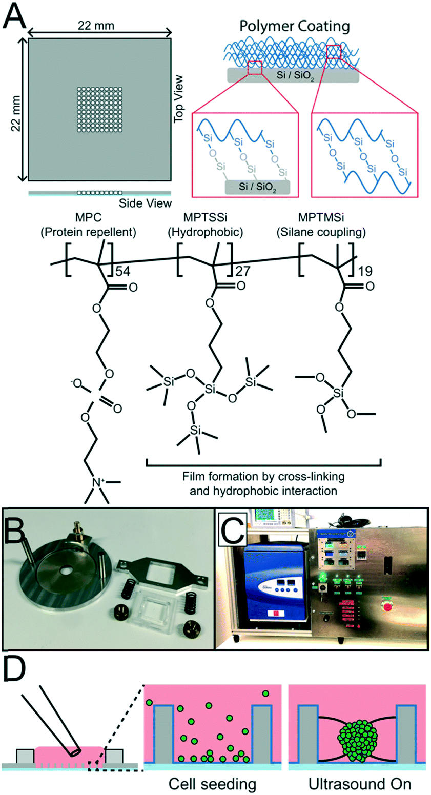 | ||
| Fig. 1 Coating, assembly and seeding of the USW device. The silicon multi-well microplate is etched with 100 micro-wells (350 μm × 350 μm, 300 μm deep), bonded to a glass plate and coated with a protein repellent copolymer coating (A) before being mounted onto the transducer (B) by clamping it with a frame. The ultrasonic tissue engineering platform is kept at constant temperature during actuation by an in-house built liquid-based temperature control system coupled to a commercial incubator (C). To produce MCTS, a single cell suspension is seeded into the multi-well microplate with a standard pipette and ultrasonic radiation forces trap cells into all 100 micro-well centers. MCTS are then formed when incubated during continuous ultrasonic actuation for 24 hours (D). | ||
The ultrasonic transducer consists of a ring-shaped, 38 mm diameter, piezo ceramic plate (APC 840, American Piezo, USA) with an 8 mm diameter central hole mounted in an aluminum frame and connected to an SMB connector. The multi-well microplate is attached to the piezo ceramic plate using a spring-loaded plastic and aluminum screw clamp. For an efficient ultrasound coupling, a thin layer of immersion oil (Immersol 518 F, Zeiss) is applied between the microplate and the piezo ceramic plate.
Protein repellent coating and coating protocol
To produce unanchored MCTS, a random poly(MPC-co-MPTSSi-co-MPTMSi) coating (Fig. 1A) was used, in which the biocompatible 2-methacryloyloxyethyl phosphorylcholine (MPC) polymer component exhibits strong protein repellent properties.30 The hydrophobic nature of 3-(methacryloyloxy)propyl-tris(trimethylsilyloxy) silane (MPTSSi), together with the silane coupling capability of 3-methacryloxypropyl trimethoxysilane (MPTMSi) onto SiO2 substrates, provides a thin coating with long-term stability in aqueous environments. The detailed protocols for copolymer synthesis and characterization are described in an earlier study.31 In this study, a 0.1 wt% solution of the random copolymer, with molar ratios MPC![[thin space (1/6-em)]](https://www.rsc.org/images/entities/char_2009.gif) :MPTSSi:MPTMSi = 54:27:19, in methanol was used to coat the SiO2 surface of the silicon walls and the glass bottom in the wells of the microplate.
:MPTSSi:MPTMSi = 54:27:19, in methanol was used to coat the SiO2 surface of the silicon walls and the glass bottom in the wells of the microplate.
The multi-well microplate was prepared for coating by cleaning for 30 min at 45 °C in an ultrasonication bath immersed in 70% ethanol followed by drying in a desiccator for 30 min. For each microplate, 100 μL coating solution was prepared from the 0.1 wt% polymer solution mixed at 90/10 w/w with 0.1 M acetic acid aqueous solution working as a catalyst. To further enhance the substrate–polymer silane coupling reaction, the cleaned and dried microplate was treated with oxygen plasma for 60 s with 50 sccm O2 and 300 W forward power (PlasmaLab 80+, Oxford Instruments) before the coating solution was applied and left at room temperature for 2 hours. The excess solution was then aspirated and the multi-well microplate was dried in a desiccator for 1 hour and in an oven at 70 °C for 1 hour. Before using the coated multi-well microplate for ultrasonic 3D culture, it was rinsed and submerged in MilliQ water to let the hydrophilic MPC polymer disentangle and face outwards for efficient protein repulsion. Before reusing the chip for a new ultrasonic 3D culture, the coated multi-well microplates were cleaned in 70% ethanol for 20 minutes and rinsed in MilliQ water.
Temperature regulation
To control the surrounding environment and regulate the temperature around 36.4 °C, the USW based MCTS culture device is placed in an in-house built PID controlled liquid-based temperature control system combined with a commercial table top incubator (GalaxyMini, LabRum) (Fig. 1C). The PID controller (KT4, Panasonic) receives temperature feedback from a type T thermocouple probe placed on the multi-well microplate and regulates the temperature control system accordingly. The control system has an accuracy of ±0.5 °C, therefore, the temperature set point was 36.4 °C to avoid overshooting above 37 °C.Inside the incubator, the multi-well microplate transducer setup is placed on a copper water block connected to the temperature control system. The system was designed to robustly regulate the transducer temperature around a desired set point independently of the applied AC actuation voltage across the piezo ceramic element which is desirable since the heating effect generated by the transducer drifts slightly over time without temperature control.
Coating characterization by X-ray photoelectron spectroscopy and ellipsometry
The surface elemental compositions of the coated surfaces were confirmed by X-ray photoelectron spectroscopy (XPS) (JPS-9010, JEOL Inc.) with a 60° incline (target: Al). Charge corrections were applied for better comparisons. The thickness of the polymer coating was measured with an optical ellipsometer (J.A. Woollam Co.) using a He/Ne laser with an incident angle of 70°. Five different samples were prepared to obtain the average values.Influence of polymer coating on ultrasonic radiation forces
The influence of the thin polymer coating on the ultrasonic radiation forces was investigated by tracking 10 μm green fluorescent polystyrene beads, seeded into the micro-wells with a regular pipette, in movies recorded during the initial ultrasonic radiation force focusing in both uncoated and coated multi-well microplates. Videos (25 fps) of the initial trapping of 10 μm fluorescent polystyrene beads were acquired while the transducer was actuated with 15 Vpp and 2.46 ± 0.5 MHz at 1 kHz frequency modulation. This was repeated twice before and after the coating was applied in 18 micro-wells in three different multi-well microplates. The fluorescent bead trajectories were captured in the Fiji plug-in TrackMate32 by first identifying all the beads in all the frames and then automatically connecting the trajectories with some manual correction for bead speed calculations.Ultrasonic MCTS culture
Adherent tumor cells were treated with 0.25% Trypsin-EDTA solution (Sigma Aldrich), collected and re-suspended at 300000 cells per mL for MCTS used in imaging experiments or 500000 cells per mL for the FACS experiment to increase the number of events collected during analysis. To produce MCTS, 100 μL of cell suspension was seeded with a regular pipette into the medium reservoir above the micro-wells (Fig. 1D). Gravity settled the cells at the bottom of the micro-wells and a couple of medium exchanges performed with a pipette ensured that no cells rested on the silicon walls above the micro-wells. A cover glass was placed on top of the PDMS gasket to minimize medium evaporation and preserve sterile conditions. The multi-well microplate was then clamped onto the transducer and placed on the cooling block inside the incubator before being connected to a function generator (DS345, Stanford Research Systems) and amplifier (75A250A, Amplifier Research). To optimize the initial cell aggregation procedure at the start of each experiment, a frequency modulation (FM) scheme was applied where the central frequency is stepped every 3 s from 2.4 MHz to 2.5 MHz in 10 kHz intervals with a 50 kHz span at a rate of 1 kHz. The procedure was iterated 20 times before the optimal FM scheme was set (2.47 MHz center frequency, 100 kHz span and 1 kHz rate). This automatic startup procedure does not require any visual access or other manual alignment procedure.33 While monitoring the microplate temperature, the amplitude was slowly increased from 20 Vpp to 30 Vpp to avoid heating the cells beyond 37 °C and allow for the cooling system to compensate for the increased heating. The cells were incubated with 5% CO2 at 36.4 °C with the PID controller set to 36.4 °C for 24 hours. After 24 hours of USW trapping, the microplate was transferred to a passive culture inside a standard incubator for another 24 hours.
Passive 3D culture in 2% agarose micro-wells
As a reference, a passive MCTS culture method based on low-adhesion agarose micro-wells was used in the live/dead flow cytometry assay. Molten 2% agarose (Sigma Aldrich) solution was poured onto the MCTS micro-mold (#12–256-Small, MicroTissues, Inc.) to obtain agarose hydrogels with 256 round-bottom micro-wells (well diameter = 400 μm). Agarose micro-well molds were transferred into a 24-well plate (Sigma Aldrich) and equilibrated in complete culture medium for 1 hour, with two medium exchanges before cell seeding. A498 renal cell carcinoma cells were re-suspended at 500000 cells per mL and seeded in the agarose gel molds (0.2 mL per gel). Cells were allowed to settle in the micro-wells for 15 min before 2 mL of complete medium was added. The cell culture was maintained at 37 °C, 5% CO2 for 48 hours before the 2% agarose-induced MCTS were harvested for further analysis.
Live/dead flow cytometry assays
The A498 renal carcinoma cell line from 2D cultures, USW induced 3D cultures and 2% agarose-induced 3D cultures were treated with Accumax (STEMCELL Technologies Inc.) for 1 hour at room temperature and washed twice in PBS. Single cell suspensions were incubated with Fixable Viability Stain 700 (BD Bioscience) according to the manufacturer's instructions. Cells were washed twice in PBS, re-suspended in PBS and analyzed by flow cytometry (BD FACSCanto II, BD Bioscience). Data analysis was performed with FlowJo Software v10 (FLOWJO, LLC). Statistical analysis was performed in the GraphPad Prism 7.0a software.Spheroid antibody staining and RIMS clearing
A492 MCTS were washed with PBS five times before being fixed with 4% paraformaldehyde (PFA) for 30 minutes at room temperature. Washing with the wash buffer (2% BSA, 0.2% Triton X-100 in PBS) 5× for 5 minutes, 15 minute incubation with the staining solution (0.5% BSA, 0.2% Triton X-100 in PBS) and 1 hour incubation with the blocking solution (2% BSA, 5% goat serum, 5% human serum, 0.2% Triton X-100 in PBS) were performed before incubation with the primary antibody (Anti-integrin beta 1 [12G10] (ab30394), Abcam, diluted 1:100) for 20 hours. After incubation with the primary antibody, the MCTS were washed 3× for 20 minutes with the wash buffer and incubated with the secondary antibody (Alexa 546 Goat anti-Mouse, Invitrogen) diluted 1:200 in the staining buffer for 4 hours. The final three washes with the washing buffer were done before counterstaining with DAPI (5 mg mL−1, Invitrogen) diluted 1:1000 in the staining buffer for 4 hours at room temperature.
To make the MCTS optically clear for deep tissue imaging, a refractive index matching solution (RIMS) containing 755 mg mL−1 Iohexol (Omnipaque 350 mg iodine per mL, GE Healthcare) was applied as the mounting medium. The RIMS reduces light scattering in the MCTS by matching the refractive index of the sample to the oil-immersion objective (n = 1.46). The Iohexol RIMS was diluted in PBS to 10%, 25%, 50% and 75% (vol/vol) and exchanged in steps before immersing the MCTS in 100% RIMS to avoid excessive fluid exchange in the MCTS which would cause spatial deformation.34 The sequential addition of RIMS with different vol/vol percentages also prevented the MCTS to escape the micro-wells up to the shared medium reservoir due to the density difference between the MCTS and RIMS.
Microscopy
Bright field images of the spheroids and movies of the fluorescent bead trapping were acquired with an inverted fluorescence and bright field microscope (Axiovert 40 CFL, Zeiss Germany) equipped with a DSLR camera (Sony α77, Sony, Japan) and a low magnification objective (EC Plan-Neofluar 2.5×/0.075, Zeiss, Germany). Optically sectioned images were acquired with a confocal light-scanning microscope (LSM 880, Zeiss, Germany) with an oil-immersion objective (Plan-Apochromat 63×/1.40 Oil DIC M27, Zeiss, Germany).Results
Protein repellent copolymer coating
The protein repellent polymer coating (schematically shown in Fig. 1A) applied on the SiO2 surface of the silicon was successfully characterized by X-ray photoelectron spectroscopy (XPS) and ellipsometry. The polymer coating thickness, measured by ellipsometry on five different samples, was 21.7 ± 5.1 nm (mean ± sd). XPS showed a clear difference in multi-well microplate surface chemistry composition before and after polymer coating was applied (Fig. 2). Significant C(1s), N(1s) and P(2p) peaks of the elements in the polymer coating were visible at expected energies only for the coated samples. To investigate the possibility to reuse the coated microplate several times before recoating, XPS measurements were also performed before and after cleaning of a polymer coated microplate. For comparison, a coated microplate was cleaned for 10 min in an ultrasonic bath submerged in 70% ethanol, followed by 1 hour of ethanol incubation, and no difference in XPS data could be seen (ESI,† Fig. S1). No autofluorescence from the copolymer coating was detected during confocal imaging and the coating was stable enough to allow for multiple MCTS cultures before new coating was needed.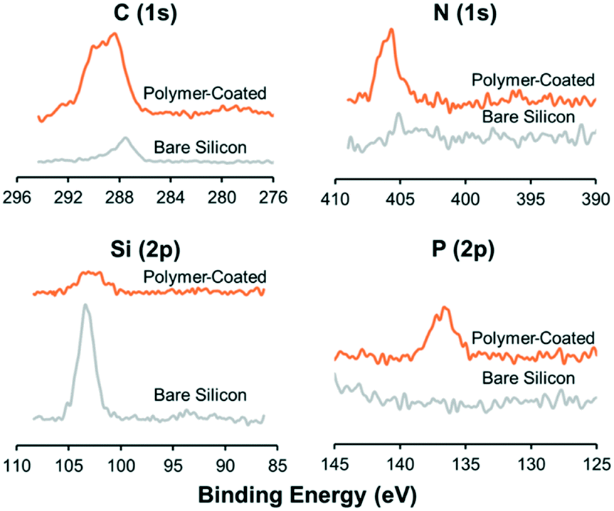 | ||
| Fig. 2 Polymer coating successfully covers the multi-well microplate. Plots show elemental surface composition on the multi-well microplate, measured by X-ray photoelectron spectroscopy (XPS), before (grey line) and after (orange line) applying the protein repellent polymer coating. Charge corrections were applied for better comparison. | ||
Ultrasonic trapping performance with coating
Since polymers are non-optimal in resonant acoustic systems, we investigated whether the protein repellent copolymer coating layer influenced the ultrasonic radiation force trapping performance indirectly by measuring the maximum speed of polystyrene beads after seeding the beads according to the procedure shown in Fig. 1d. In total, 6354 beads were detected (Fig. 3A I) and their trajectories (Fig. 3A II) were analyzed (3127 trajectories in the un-coated microplate and 3227 trajectories in the coated microplate) and the maximum bead speed distributions for the two cases overlapped closely (Fig. 2B) with a median maximum bead speed of 214 μm s−1 in the coated microplate compared to 220 μm s−1 in the un-coated microplate. The two maximum speed distributions show no statistically significant difference determined by pairwise Mann–Whitney U test. Thus, coating did not affect trapping efficiency.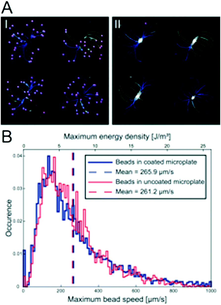 | ||
| Fig. 3 Polymer coating does not influence trapping efficiency. The bead trajectories were calculated semi-automatically from the ImageJ plug-in TrackMate which finds all the beads before the ultrasound is turned on (A I) and connects trajectories for each individual bead until they are trapped in the micro-well center (A II). Each line in the images corresponds to a bead trajectory and the color indicates maximum bead velocity. Histogram of the maximum speed distribution of 10 μm polystyrene beads (B) during the initial ultrasound trapping in a coated (blue line, N = 3227) and un-coated (red line, N = 3127) multi-well microplates. The median maximum bead speed is 214 μm s−1 in the coated microplate (dashed blue line) and 220 μm s−1 in the uncoated microplate (dashed red line). | ||
MCTS formation and characterization
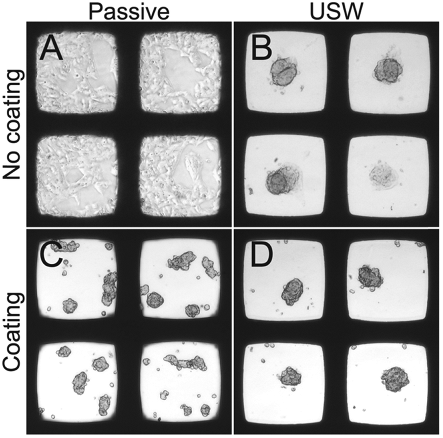
To investigate the flexibility of the MCTS platform in terms of cell line choice, we cultured MCTS from four different adherent cell line suspensions (Fig. 4). The hepatocellular carcinoma cell line HepG2 readily formed both anchored and un-anchored MCTS after 48 hours (24 h with ultrasound followed by 24 h without ultrasound) in an uncoated and a coated microplate, respectively, while renal carcinoma cell lines A498 and ACHN did not form a stable anchored MCTS in the uncoated microplate. When using the A498 cell line in the uncoated microplate, the ultrasonic radiation forces, using the same actuation scheme as in the coated microplate, were too weak to prevent cell migration. The thyroid carcinoma LUTC-2 cell line and the ACHN cell line showed initial anchored MCTS formation after 24 hours of USW trapping but after subsequent passive culture (no USW) for 24 hours the cells migrated out over the glass bottom and over time formed a 2D layer (Fig. 4). The quality of the 3D culture directly after 24 h of ultrasonication (cf. first panel in Fig. 4) can be improved by increasing the actuation voltage over the ultrasound transducer (data not shown), but this did not prevent the cell spreading at the bottom after the ultrasound was turned off (cf. second panel in Fig. 4). The results clearly motivate the use of the combined USW + coating culture method for all tested cell types except for HepG2 (Table 1).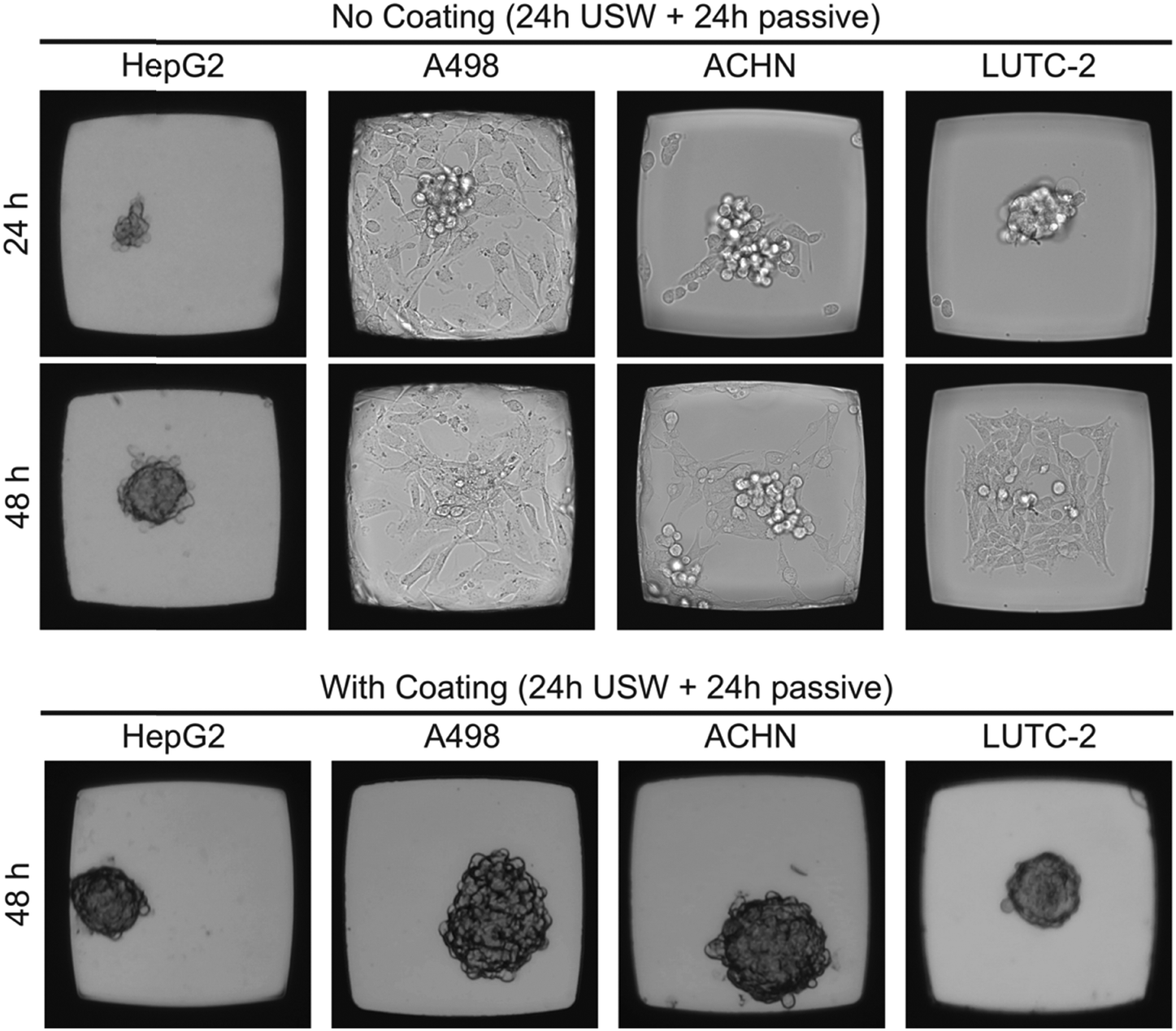 | ||
| Fig. 4 Protein repellent coating enables MCTS formation independent of the cell line. Representative bright field images of HepG2, A498, ACHN and LUTC-2 cell lines cultured with and without coating in the multi-well microplate for 24 hours with USW exposure followed by 24 hours of passive culture. Each micro-well is 350 μm wide. | ||
| Cell lines | ||||
|---|---|---|---|---|
| HepG2 | A498 | ACHN | LUTC-2 | |
| +++Exclusively one 3D spheroid per well.++One major 3D spheroid per well with a minor substrate-interacting 2D monolayer at the bottom.+One minor 3D spheroid per well with a major substrate-interacting 2D monolayer at the bottom.2DExclusively a monolayer 2D culture in the well.3D*A multitude of differently sized 3D spheroids per well.—Not tested. | ||||
| No coating; 48 h USW off | 2D | — | — | — |
| No coating; 24 h USW on | +++ | + | ++ | +++ |
| No coating; 24 h USW on + 24 h USW off | +++ | 2D | + | + |
| With coating; 48 h USW off | 3D* | — | — | — |
| With coating; 24 h USW on + 24 h USW off | +++ | +++ | +++ | +++ |
Since HepG2 was the only cell line among the four tested cell lines that was able to efficiently grow in 3D without the use of the protein repellent coating (cf.Fig. 4), it is of interest to further investigate the importance of the ultrasound 3D culture method when using a coating for this cell line. For these reasons, HepG2 cells were cultured in the multi-well microplate with and without the protein repellent coating and with and without USW trapping (Fig. 5).
 | ||
| Fig. 5 Bright field microscopy images of HepG2 cells cultured in the multi-well microplate with and without coating or ultrasound. Four conditions: 48 hours of passive culture in an un-coated microplate (A), 24 hours active + 24 hours passive culture in uncoated microplate (B), 48 hours of passive culture in a coated microplate (C) and 24 hours active + 24 hours passive culture in a coated microplate (D). Each micro-well is 350 μm wide. | ||
When HepG2 cells are cultured for 48 hours in the multi-well microplate without coating and without ultrasonic manipulation they grow like a 2D monolayer (Fig. 5A) while 3D hemispherical (ESI,† Fig. S2A) structures are formed during USW trapping for 24 hours followed by passive culture for 24 hours in an uncoated microplate (Fig. 5B). When introducing the protein repellent polymer coating, HepG2 cells cultured without USW trapping for 48 hours exhibit numerous small spontaneously formed 3D structures (Fig. 5C). On the other hand, HepG2 cells cultured in a coated multi-well microplate for 24 hours with continuous ultrasonic actuation followed by 24 hours of passive culture form unattached (ESI,† Fig. S2B) 3D MCTS (Fig. 5D) resting at the micro-well bottom.
Image analysis based MCTS characterization
The size, shape and number of MCTS were investigated from a series of experiments according to the examples shown in Fig. 5. For this, we analyzed the MCTS by using an automatic characterization method based on bright field images. The more concentrated MCTS size distribution and smaller median area (Fig. 6A) in the coated microplate indicate a more uniform and compact MCTS formation (mean ± sd = 9250 ± 3370 μm2) in the coated microplate compared to the uncoated microplate (12400 ± 5560 μm2). This is also supported by lower light transmission through the MCTS (ESI,† Fig. S3) in the coated microplate (63.5 ± 5.2%) compared to the uncoated microplate (77.7 ± 12.7%) (Fig. 6B). The wide distribution and extreme outliers in the area distribution for MCTS cultured in the coated microplate without any ultrasonic trapping (5350 ± 6940 μm2) should be noted, which underscores the need for USW trapping to produce MCTS of uniform shape with a high degree of reproducibility. Minor differences can be seen in terms of the number of aggregates and single cells per well between active cultures using coated and uncoated microplates (Fig. 6C and D), while the passive culture in the coated microplate exhibited multiple aggregates (5.1 ± 2.0 cell aggregates per well) and single cells (5.3 ± 5.6 single cells per well) distributed in the micro-wells. This suggests that HepG2 cells can spontaneously form MCTS without any USW trapping on a non-adherent surface, but in an uncontrolled manner resulting in inconsistent sizes and numbers of MCTS.
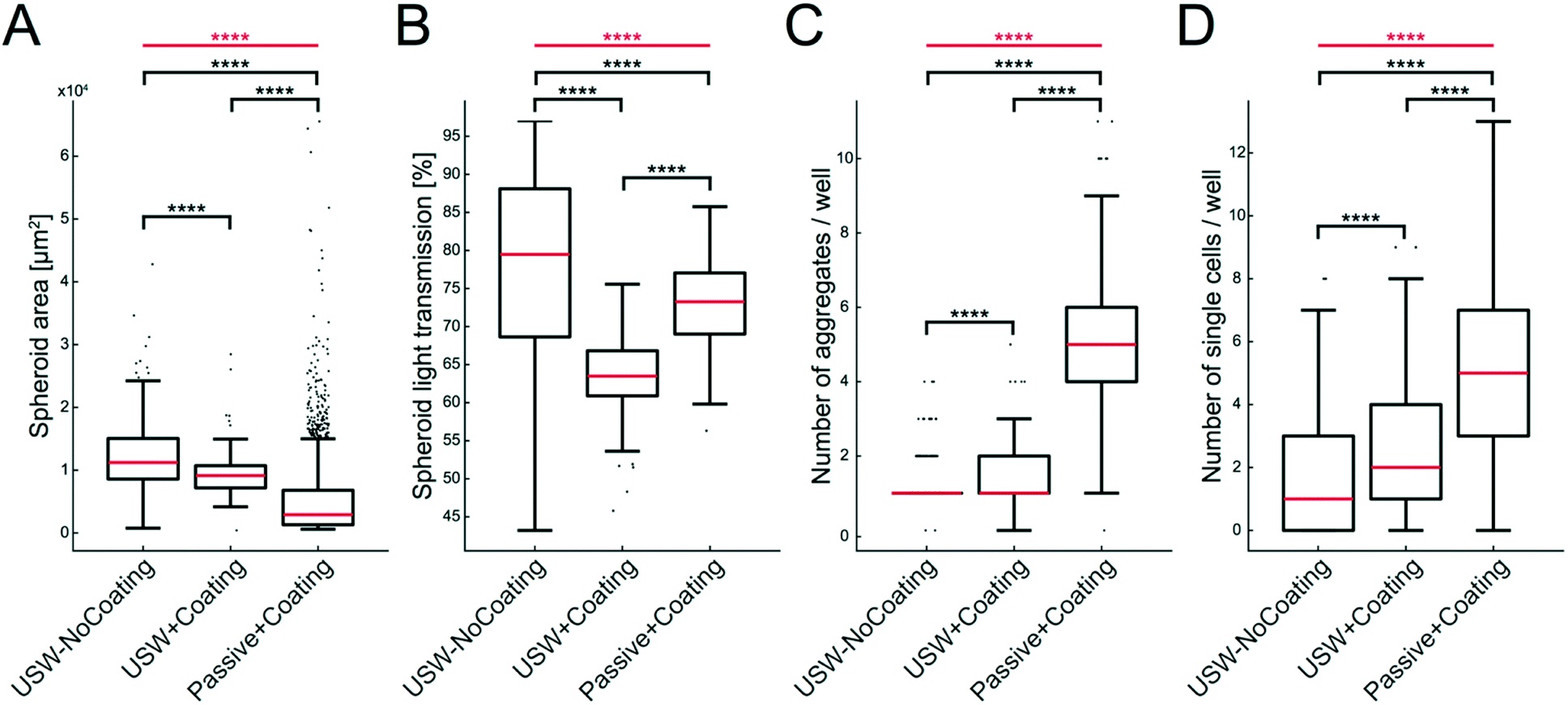 | ||
| Fig. 6 Characterization of MCTS with and without coating during active and passive culture of HepG2 cells. Data of MCTS area (A), light transmission through the MCTS (B), number of aggregates per well (C) and number of single cells (D) are shown in the boxplots for MCTS produced under three different conditions: USW-NoCoating (24 hours active + 24 hours passive culture in an uncoated microplate (Fig. 3B)), USW+Coating (24 hours active culture + 24 hours passive culture in a coated microplate (Fig. 3D)) and Passive+Coating (24 hours of passive culture in a coated microplate (Fig. 3C)). The box indicates the 25th and 75th percentiles with a red line marking the median. Whiskers shows the furthest observation that is less than 1.5 times the interquartile range away from the box edge and outliers are marked with a black dot. The horizontal red lines and stars indicate the overall significance of the three sets of data in each plot determined by the Kruskal–Wallis test (****; p < 0.0001). The horizontal black lines and stars indicate the pairwise significance between sets of data determined by the Mann–Whitney U test. | ||
Flow cytometry analysis of A498 MCTS
To investigate cell viability in the MCTS formed by USWs and compare it to MCTS formed in the agarose wells and cells cultured in 2D, MCTS were disintegrated into singe cell suspensions and analyzed by flow cytometry. The fraction of live cells was determined in A498 MCTS cultured for 48 hours in the active USW MCTS culture platform (Fig. 7A), in passive 2% agarose round bottom micro-wells (Fig. 7B) or in grown in 2D (Fig. 7C). From 6 independent experiments, we could not find any statistically significant difference in the fractions of living (Fig. 7D) and dead cells (Fig. 7E) between the three cases, which indicates that the active culture conditions do not induce cell death when cells are exposed to USWs for 24 hours and cells in the center of the MCTS do not die due to a lack of nutrients as has been described for larger spheroids.15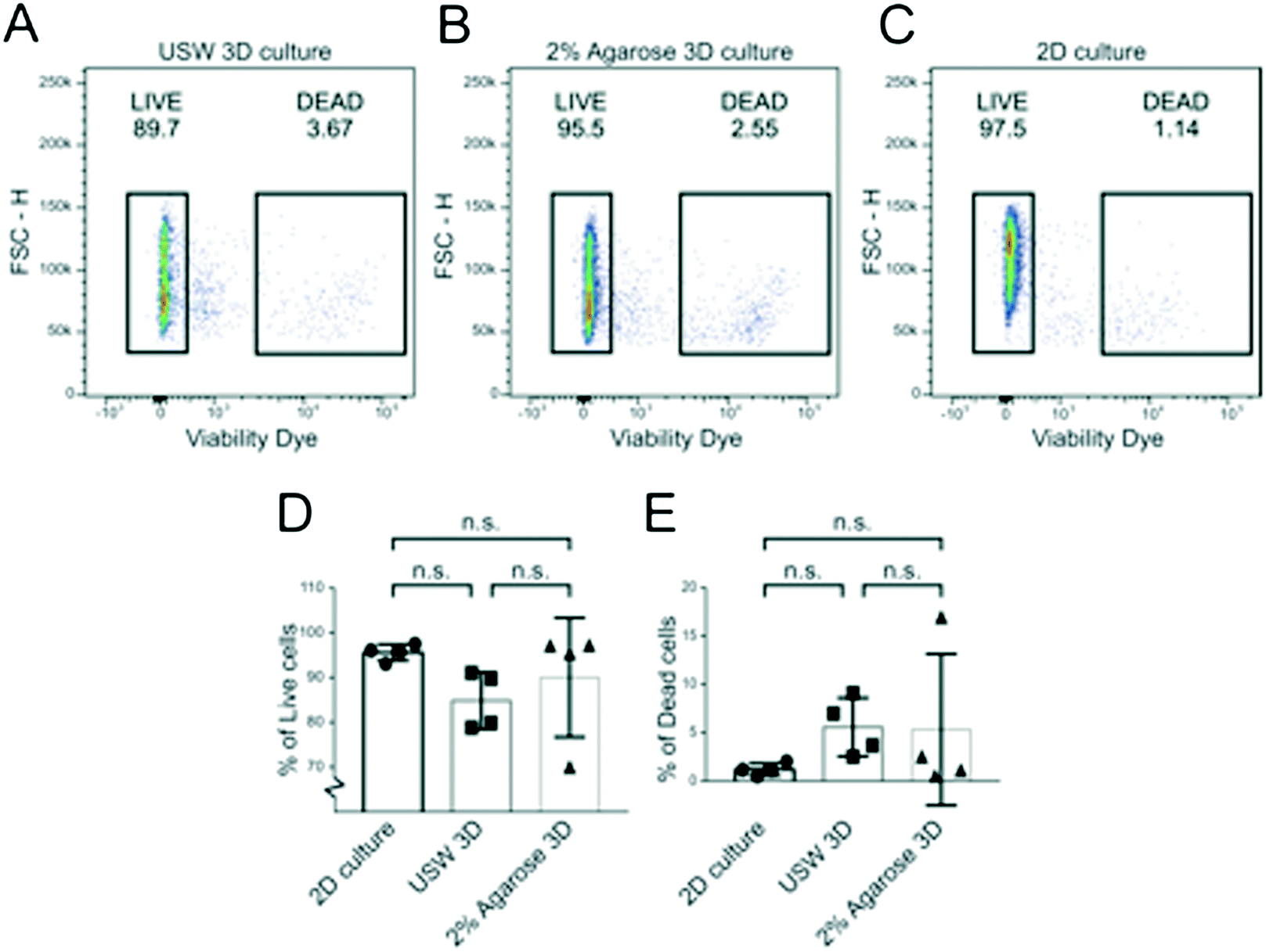 | ||
| Fig. 7 Renal carcinoma cells display a similar viability in 2D and 3D cultures. Flow cytometry dot plot graphs of A498 cells cultured in 2D culture (A), USW 3D MCTS culture (B) and 2% agarose-induced 3D culture (C). Here, the viability dye intensity (log scale) on the x-axis and the cell dimension (FSC-H: forward scatter; linear scale) on the y-axis are plotted. Live cells (LIVE gate) are defined as viability dye negative; dead cells (DEAD gate) are defined as viability dye positive cells; percentages are indicated above each gate. Graphs showing the percentage of live (D) and dead (E) cells obtained from six independent experiments. Statistical significance has been evaluated with one-way ANOVA with Tukey's multiple comparison test (n.s. = not significant). | ||
On-chip confocal whole MCTS imaging
To highlight the potential for on-chip high-content imaging of whole MCTS, we stained A498 MCTS with antibodies against integrin beta-1 and the nuclei with DAPI before mounting the MCTS in an Iohexol RIMS solution. This enabled whole MCTS confocal imaging by removing light scattering interfaces so that optical sections could be captured throughout the whole MCTS volume (ESI,† Fig. S4). Confocal z-stacks acquired from A498 MCTS cultured for 24 hours, 48 hours and 96 hours show that the staining protocol worked and an even staining of beta-1 integrin could be detected throughout the volume (Fig. 8). Qualitatively, one can see that the cell density and the spatial organization of integrin expression change in MCTS cultures fixed after 24 hours compared to 48 hours and 96 hours. We also used the DAPI-based imaging method for A498 MCTS and counted manually the number of nuclei in seven different spheroids, resulting in 208 ± 36 cells per MCTS. Since we used the same seeding procedure for all cell cultures, a similar number is expected in the experiments with the other cell lines.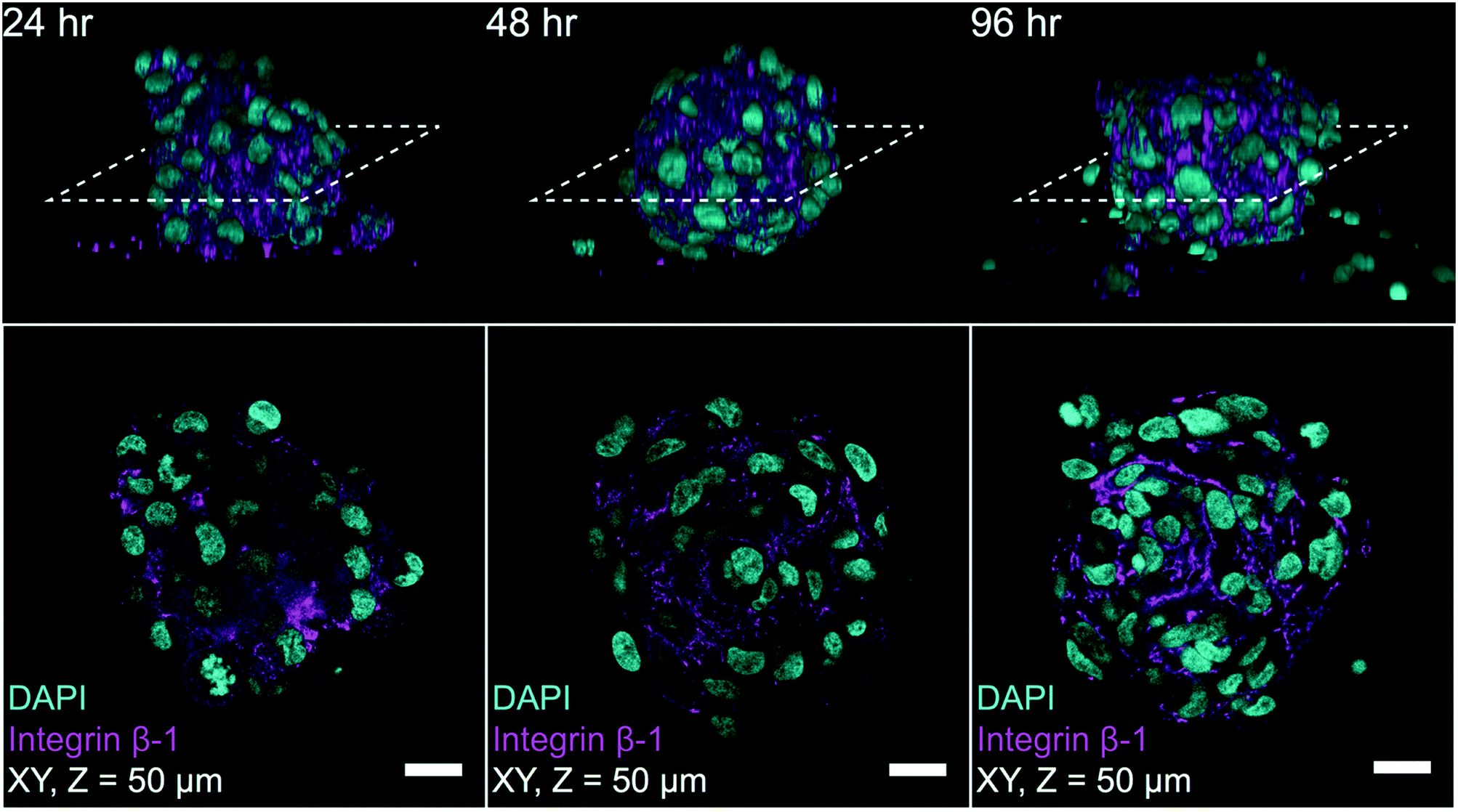 | ||
| Fig. 8 Confocal on-chip imaging of RIMS mounted MCTS with immunostaining against integrin β-1 and DAPI. Fixation, staining and RIMS mounting of MCTS at 24 hours, 48 hours and 96 hours were performed before confocal z-stack imaging. Each column in the figure shows a representative image of a MCTS from each time point where the top row depicts the YZ side view of a 3D reconstruction and the dashed line indicates the location of the optical section shown in the bottom row. The bottom row shows an optical section 50 μm deep into the MCTS for each time point (scale bar 20 μm). | ||
Discussion and conclusion
We have demonstrated an ultrasonic standing wave (USW) based multicellular tumor spheroid (MCTS) platform where unanchored MCTS can be formed by USWs and a protein repellent polymer coating in a multi-well microplate. In contrast to previous ultrasound-based techniques, this method is compatible with any tested adherent cell type. This allows for both on- and off-chip characterization methods of various cancer relevant MCTS with emphasis on on-chip optical characterization.The protein repellent copolymer coating, originally developed for long-term suppression of non-specific protein adsorption on PDMS surfaces,31 was applied to the silicon/glass multi-well microplate. Complete inhibition of cell adhesion and XPS and ellipsometry measurements showed that the coating was evenly distributed across the surface of the microwell (Fig. 2). The coating also further protects cells by minimizing bare silicon exposure which can affect cell viability during long term experiments.35 The strong bonding of the copolymers to the micro-well surface resulted in a durable coating which allowed for multiple experiment repetitions before recoating was needed. This study in combination with a separate FRET study, where the copolymer coating was used in a glass chip,36 suggests that this copolymer coating could be beneficial where a thin and durable anti-fouling coating is needed for long-term experiments.
Since polymers are in general avoided in bulk acoustic wave resonant systems due to the sub-optimal acoustic properties, it was of interest to investigate whether the USW trapping performance would decrease when introducing the copolymer coating.17 When trying to assess the USW trapping reduction through particle tracking, it was found that the copolymer coating did not interfere with the ultrasonic radiation forces. This could be explained by the thin coating thickness (21.7 ± 5.1 nm) compared to the ultrasound wavelength (∼1 mm). The acoustic intensity transmission coefficient equation through two boundaries37 is reduced to the equation describing the intensity transmission coefficient with only one boundary when the middle layer is very thin compared to the wavelength and thus the coating can be considered acoustically transparent. Therefore, the micro-well walls could be described as purely silicon, which was confirmed by our bead velocity measurements.
Not only is the protein repellent polymer coating important for reducing substrate–cell interactions, it also improves the 3D model quality and enables un-anchored MCTS formation. To confirm this, an in-house automatic MCTS characterization script was used to investigate differences between anchored and unanchored HepG2 MCTS (Fig. 6). We note that the unanchored MCTS exhibited a more compact and consistent result after 24 hours active + 24 hours passive culture. However, we have previously shown that longer USW incubation times (over 48 hours) also yield a high percentage of anchored HepG2 MCTS with a hemispherical shape.25 Since the automatic MCTS characterization script is based on bright field transmission microscopy images, dynamic events at a spheroid level, such as growth or MCTS defragmentation, can be captured with high temporal resolution on living MCTS without any fluorescent staining or other treatment which opens up for high-throughput drug screening applications. Also, the possibility to grow cells in a 2D monolayer by introducing neither coating nor USW into the multi-well microplate allows for control cultures.
The HepG2 cell line is commonly used to demonstrate MCTS formation in various techniques due to its fast aggregation time and possible applications in drug screening investigating hepatotoxicity and drug metabolism.10,11,20 However, in order to demonstrate the coating importance for MCTS formation we also used the renal carcinoma cell line A498 derived from transformed kidney tissue, the renal carcinoma cell line ACHN derived from a metastatic site (pleural effusion) and the low-passage cell line LUTC-2 that has been established from resected thyroid carcinomas (Fig. 4). These three cell lines differ in terms of origin, metastatic site and number of passages, and are therefore a suitable choice for testing the applicability and robustness of our 3D culture method. Among all tested cell lines, we made a more detailed characterization of A498 (Fig. 7 and 8) not only due to its relevance as a model for solid renal cell carcinoma, with applications in e.g. immunotherapy research,38,39 but also to demonstrate that we are able to form spheroids with a highly motile and substrate-interacting cell line that does not form spheroids when using the ultrasound method only (cf.Fig. 4).
To complement automatic characterization at the spheroid level, protocols for single cell analysis by flow cytometry were developed. To demonstrate the protocol, live/dead flow assays of A498 renal cell carcinoma cultured in parallel in 2D, ultrasonic 3D and passive 2% agarose 3D were performed and no statistically significant difference was observed. Usually, large MCTS with diameters over 450–500 μm show necrotic cores; so the retained viability in the MCTS indicates the absence of a necrotic core, which can be explained by the comparably small MCTS diameter around 100 μm.15 This further supports earlier studies reporting retained viability of cells trapped through USWs.40,41
While flow cytometry can provide detailed analysis at the single cell level, the spatial and structural information is lost. The main obstacle for acquiring structural information from the whole MCTS is the internal light scattering which prevents deep tissue imaging. Therefore, an Iohexol based refractive index matching solution (RIMS) protocol was developed where all 100 MCTS were treated simultaneously while being retained in the micro-wells. The RIMS protocol is diffusion-based and therefore slower than syringe-pump-based devices designed for rapid MCTS interstitial fluid exchange.34 But since a standard pipette was the only tool needed for fluid manipulation in the platform, a lower technical threshold and a great reduction in required labor were achieved. This relatively fast RIMS technique was shown to be compatible with immunofluorescent staining (Fig. 8) and thus paves the way for whole MCTS imaging without the need for MCTS harvest and slicing to get structural and functional information.
While only monoculture MCTS were used in this study, multiple cell lines could easily be introduced for more complex co-culture tumor models. One major advantage with using USWs to produce MCTS is the modularity in which ordered and haphazard tissue structures can be created. We believe that layered MCTS of multiple cell lines can be cultured by sequential cell seeding of the different cell lines. This could open up new possibilities for tumor models of higher complexity or modelling healthy tissue for various uses such as organ-on-a-chip applications where a higher degree of ordered structures is needed.
Altogether, we have presented a MCTS culture platform that can be tailored to meet many of the requirements of cancer researchers: high MCTS formation yield, automatic analysis, low technical threshold and the possibility to perform the whole experiment in a single plate.
Conflicts of interest
There are no conflicts to declare.Acknowledgements
We thank the Swedish Research Council, the Swedish Foundation for Strategic Research, The Swedish Cancer Society, The Swedish Childhood Cancer Foundation and the Stockholm County Council for financial support.References
- P. Lu, V. M. Weaver and Z. Werb, J. Cell Biol., 2012, 196, 395–406 CrossRef PubMed.
- C. J. Lovitt, T. B. Shelper and V. M. Avery, Biology, 2014, 3, 345–367 CrossRef PubMed.
- H. Yu, J. K. Mouw and V. M. Weaver, Trends Cell Biol., 2011, 21, 47–56 CrossRef PubMed.
- E. Fennema, N. Rivron, J. Rouwkema, C. van Blitterswijk and J. de Boer, Trends Biotechnol., 2013, 31, 108–115 CrossRef PubMed.
- C. R. Thoma, M. Zimmermann, I. Agarkova, J. M. Kelm and W. Krek, Adv. Drug Delivery Rev., 2014, 69–70, 29–41 CrossRef PubMed.
- L. Yu, M. C. Chen and K. C. Cheung, Lab Chip, 2010, 10, 2424–2432 RSC.
- M. Jang, I. Koh, S. J. Lee, J. H. Cheong and P. Kim, Sci. Rep., 2017, 7, 41541 CrossRef PubMed.
- D. Antoni, H. Burckel, E. Josset and G. Noel, Int. J. Mol. Sci., 2015, 16, 5517–5527 CrossRef PubMed.
- S. Raghavan, M. R. Ward, K. R. Rowley, R. M. Wold, S. Takayama, R. J. Buckanovich and G. Mehta, Gynecol. Oncol., 2015, 138, 181–189 CrossRef PubMed.
- T. Tamura, Y. Sakai and K. Nakazawa, J. Mater. Sci.: Mater. Med., 2008, 19, 2071–2077 CrossRef PubMed.
- B. Patra, Y. H. Chen, C. C. Peng, S. C. Lin, C. H. Lee and Y. C. Tung, Biomicrofluidics, 2013, 7, 54114 CrossRef PubMed.
- T. M. Achilli, J. Meyer and J. R. Morgan, Expert Opin. Biol. Ther., 2012, 12, 1347–1360 CrossRef PubMed.
- H. Jaganathan, J. Gage, F. Leonard, S. Srinivasan, G. R. Souza, B. Dave and B. Godin, Sci. Rep., 2014, 4, 6468 CrossRef PubMed.
- A. Ivascu and M. Kubbies, J. Biomol. Screening, 2006, 11, 922–932 CrossRef PubMed.
- S. Nath and G. R. Devi, Pharmacol. Ther., 2016, 163, 94–108 CrossRef PubMed.
- M. Wiklund, Lab Chip, 2012, 12, 2018–2028 RSC.
- A. Lenshof, M. Evander, T. Laurell and J. Nilsson, Lab Chip, 2012, 12, 684–695 RSC.
- A. Lenshof, C. Magnusson and T. Laurell, Lab Chip, 2012, 12, 1210–1223 RSC.
- M. Evander and J. Nilsson, Lab Chip, 2012, 12, 4667–4676 RSC.
- J. Liu, L. A. Kuznetsova, G. O. Edwards, J. Xu, M. Ma, W. M. Purcell, S. K. Jackson and W. T. Coakley, J. Cell. Biochem., 2007, 102, 1180–1189 CrossRef PubMed.
- D. Bazou, W. T. Coakley, A. J. Hayes and S. K. Jackson, Toxicol. In Vitro, 2008, 22, 1321–1331 CrossRef PubMed.
- S. Li, P. Glynne-Jones, O. G. Andriotis, K. Y. Ching, U. S. Jonnalagadda, R. O. Oreffo, M. Hill and R. S. Tare, Lab Chip, 2014, 14, 4475–4485 RSC.
- K. Chen, M. Wu, F. Guo, P. Li, C. Y. Chan, Z. Mao, S. Li, L. Ren, R. Zhang and T. J. Huang, Lab Chip, 2016, 16, 2636–2643 RSC.
- Y. Kurashina, K. Takemura and J. Friend, Lab Chip, 2017, 17, 876–886 RSC.
- A. E. Christakou, M. Ohlin, B. Onfelt and M. Wiklund, Lab Chip, 2015, 15, 3222–3231 RSC.
- D. E. Discher, P. Janmey and Y. L. Wang, Science, 2005, 310, 1139–1143 CrossRef PubMed.
- B. Vanherberghen, O. Manneberg, A. Christakou, T. Frisk, M. Ohlin, H. M. Hertz, B. Onfelt and M. Wiklund, Lab Chip, 2010, 10, 2727–2732 RSC.
- M. Ohlin, A. E. Christakou, T. Frisk, B. Önfelt and M. Wiklund, J. Micromech. Microeng., 2013, 23, 035008 CrossRef.
- T. W. Frisk, M. A. Khorshidi, K. Guldevall, B. Vanherberghen and B. Onfelt, Biomed. Microdevices, 2011, 13, 683–693 CrossRef PubMed.
- K. Ishihara, H. Oshida, Y. Endo, T. Ueda, A. Watanabe and N. Nakabayashi, J. Biomed. Mater. Res., 1992, 26, 1543–1552 CrossRef PubMed.
- K. Nagahashi, Y. Teramura and M. Takai, Colloids Surf., B, 2015, 134, 384–391 CrossRef PubMed.
- J. Y. Tinevez, N. Perry, J. Schindelin, G. M. Hoopes, G. D. Reynolds, E. Laplantine, S. Y. Bednarek, S. L. Shorte and K. W. Eliceiri, Methods, 2017, 115, 80–90 CrossRef PubMed.
- K. Olofsson, Master Degree Thesis, KTH Royal Institute of Technology, 2016 Search PubMed.
- Y. Y. Chen, P. N. Silva, A. M. Syed, S. Sindhwani, J. V. Rocheleau and W. C. Chan, Proc. Natl. Acad. Sci. U. S. A., 2016, 113, 14915–14920 CrossRef PubMed.
- G. Voskerician, M. S. Shive, R. S. Shawgo, H. v. Recum, J. M. Anderson, M. J. Cima and R. Langer, Biomaterials, 2003, 24, 1959–1967 CrossRef PubMed.
- M. Saito, S. Kamonprasertsuk, S. Suzuki, K. Nanatani, H. Oikawa, K. Kushiro, M. Takai, P. T. Chen, E. H. Chen, R. P. Chen and S. Takahashi, J. Phys. Chem. B, 2016, 120, 8818–8829 CrossRef PubMed.
- L. E. Kinsler, A. R. Frey, A. B. Coppens and J. B. Sanders, Fundamentals of Acoustics, Wiley, New York, 3rd edn, 1982 Search PubMed.
- P. S. Goedegebuure, L. M. Douville, H. Li, G. C. Richmond, D. D. Schoof, M. Scavone and T. J. Eberlein, J. Clin. Oncol., 1995, 13, 1939–1949 CrossRef PubMed.
- R. J. Motzer, B. Escudier, D. F. McDermott, S. George, H. J. Hammers, S. Srinivas, S. S. Tykodi, J. A. Sosman, G. Procopio, E. R. Plimack, D. Castellano, T. K. Choueiri, H. Gurney, F. Donskov, P. Bono, J. Wagstaff, T. C. Gauler, T. Ueda, Y. Tomita, F. A. Schutz, C. Kollmannsberger, J. Larkin, A. Ravaud, J. S. Simon, L. A. Xu, I. M. Waxman, P. Sharma and I. CheckMate, N. Engl. J. Med., 2015, 373, 1803–1813 CrossRef PubMed.
- M. Ohlin, I. Iranmanesh, A. E. Christakou and M. Wiklund, Lab Chip, 2015, 15, 3341–3349 RSC.
- J. Hultstrom, O. Manneberg, K. Dopf, H. M. Hertz, H. Brismar and M. Wiklund, Ultrasound Med. Biol., 2007, 33, 145–151 CrossRef PubMed.
Footnote |
| † Electronic supplementary information (ESI) available. See DOI: 10.1039/c8lc00537k |
| This journal is © The Royal Society of Chemistry 2018 |