
Highly stable biomolecule supported by gold nanoparticles/graphene nanocomposite as a sensing platform for H2O2 biosensor application†
Balamurugan
Thirumalraj
a,
Chellakannu
Rajkumar
a,
Shen-Ming
Chen
 *a and
Palani
Barathi
b
*a and
Palani
Barathi
b
aDepartment of Chemical Engineering and Biotechnology, National Taipei University of Technology, No. 1, Section 3, Chung-Hsiao East Road, Taipei 106, Taiwan, Republic of China. E-mail: smchen78@ms15.hinet.net; Fax: +886 2270 25238; Tel: +886 2270 17147
bElectrochemical Energy Research Lab, Centre for Nanoscience and Technology, Pondicherry University, Puducherry, 605014, India
First published on 3rd September 2016
Abstract
A highly active and stable composite of hemin (HN) supported by reduced graphene oxide/gold nanoparticles (HN–RGO/AuNPs) was prepared by one-pot hydrothermal method. The physicochemical properties of the as-prepared composites were characterized by field emission scanning electron microscopy (FESEM), transmission electron microscopy (TEM), UV-vis spectroscopy, Raman spectroscopy and X-ray diffraction technique (XRD). The HN–RGO/AuNP-modified electrode shows a stable and well-defined, surface-confined redox couple at an apparent formal potential of −0.317 V vs. Ag|AgCl with a surface coverage value of 2.239 × 10⁻¹⁰ mol cm−2. Compared with HN, HN–GO and HN–RGO, the HN–RGO/AuNP-modified electrode exhibits excellent electrocatalytic activity towards hydrogen peroxide (H2O2). Under optimum conditions, the HN–RGO/AuNP-modified electrode shows a wide linear response ranges from 0.05 μM to 518.15 μM towards H2O2 with a fast response time (3 s). The calculated sensitivity and limit of detection (LOD) of the biosensor were 3.99 μA μM−1 cm−2 and 16 nM, respectively. In addition, the Michaelis–Menten constant value of the biosensor is 0.13 mM, which indicates the high affinity of HN towards the reduction of H2O2. The proposed biosensor displays high sensitivity and selectivity towards H2O2 in the presence of common biologically co-existing species. The biosensor shows an acceptable practical ability in human serum, contact lens solution and milk samples with an appreciable recovery.
1. Introduction
The design and development of peroxidase-mimicking enzymes with excellent catalytic activity and high substrate selectivity is the subject of much interest in analytical, biochemical and clinical chemistry due to the limitations of natural enzymes, which are used for the sensing of biological micromolecules such as H2O2, glucose, dopamine, uric acid, ascorbic acid, and so on.1,2 Hemin (HN) is an iron-containing porphyrin molecule that acts as an active center of the protein family, e.g., cytochrome, hemoglobin, myoglobin and peroxidase.3 In particular, the direct electrochemistry of HN, with its known structure, is used as a model enzyme that can provide the mechanism for electron transport in biological systems. It is commercially available at low cost and is highly stable. The electron-rich and planar HN can be used as a peroxidase enzyme in the electrocatalysis of small molecules involved in related biological processes,4 which are produced by red blood cells from human blood processes and lower the production of certain enzymes in the body. However, the direct application of HN faces challenges due to its molecular aggregation in aqueous solution to form dimers and also to its oxidative self-destruction in oxidizing media, which causes passivation of its catalytic activity.5 In recent years, carbon nanomaterials have received much interest in the research community for various potential applications including sensors, batteries, electronics and so on.6,7In particular, reduced graphene oxide (RGO) is a single-layered 2D material that has raised much attention in electrochemical sensor and biosensor applications8–10 owing to its unique structure and superior properties such as large specific surface area, superior mechanical strength, high thermal and electrical conductivities etc.11 Covalent and non-covalent interactions can be used to functionalize RGO sheets via the stacking interaction between RGO and other aromatic molecules such as HN, ascorbic acid or tetrathiafulvalene under mild conditions.12–14 On the other hand, the attractive electrocatalytic activity of metal nanoparticles have been explored in different potential applications such as surface plasmonics, biosensors, diagnostics and catalysis.15–18 Moreover, the noble metal nanoparticles are widely used as sensitive probes for immobilization on graphene-based biosensors to improve their catalytic activity and sensing performance.19 In particular, gold nanoparticles (AuNPs) are extensively used for electron transfer reactions due to their higher surface area, good conductivity and biocompatibility.20 Owing to their special properties, AuNPs can enhance the electron transfer between the redox centers and exhibit an exceptional electrocatalytic activity towards the reduction of H2O2.21
Hydrogen peroxide (H2O2) is the simplest peroxide, a colorless liquid with bitter taste. It plays an important role in biological systems and is used for different potential applications such as in the pulp and paper bleaching industry, as propellants in rockets, as cleaning and disinfecting agents in domestic use, and as alternative medicine for emphysema, influenza and AIDS.22,23 Different nanomaterials have been constructed with peroxidase-like natural enzymes for electrocatalytic H2O2 detection, which can, instead of the peroxidase, oxidize H2O2 on the substrate.1,24 The possibility of incorporating HN with RGO through π–π interaction, for example, in hemin–graphene hybrid nanosheets,25 heat-treated hemin-supported graphene,26 hemin–graphene/poly(3,4-ethylenedioxythiophene) nanocomposite,4 DNA/hemin/nafion–graphene, reduced graphene oxide/graphene sheets-hemin–Au nanoparticles,27,28 hemin immobilized on chemically converted graphene29 and graphite-single walled carbon nanotube-hemin,30 has been studied to utilize the electrocatalytic activity of HN-based biosensors in different applications. Many of these studies have some limitations and drawbacks such as lower catalytic activity, poor redox features, poor selectivity and complicated preparation procedures. In particular, heat-treated, hemin–graphene-modified electrodes showed poor redox signature,26 and hemin-functionalized graphene oxide suffered from serious interference with ascorbic acid, dopamine and uric acid.31 More recently, Gu et al. reported a reduced graphene oxide–hemin–Au nanohybrid for H2O2 sensing that shows poor sensitivity and lower linear range.27 However, compared with the previous report, our developed biosensor exhibited excellent electrocatalytic activity and higher sensitivity with a wide linear response towards the reduction of H2O2.
In this study, we report a one-pot synthesis of HN-functionalized reduced graphene oxide/gold nanoparticle (HN–RGO/AuNPs) composite prepared by a simple hydrothermal method. The HN–RGO/AuNP-modified electrode showed a well-defined redox couple and higher electrocatalytic activity than the HN-, HN–GO-, and HN–RGO-modified electrodes. The electrocatalytic activity and sensing performance of HN–RGO/AuNPs are much higher than those of previously reported hemin-based H2O2 biosensors. Based on this, we report a highly active and stable HN–RGO/AuNP composite for the sensitive and selective electrochemical detection of H2O2. The selectivity, higher stability and practicality of the proposed biosensor has also been crucially assessed and established. The biosensor was used for the determination of H2O2 level in human blood serum, contact lens solution and milk samples for practical applications.
2. Experimental
2.1. Materials
Hemin (BioXtra, from porcine, ≥98%) and chloroauric acid (HAuCl4·3H2O, ≥49.0% Au basis) were supplied from Sigma-Aldrich and used without further purification. Glucose and 30% ammonium hydroxide (NH4OH) solution were obtained from Sigma-Aldrich. Contact lens solution (containing 3% H2O2) was purchased from China Chemical and Pharmaceutical, Taipei, Taiwan. Human blood serum sample was collected from Valley Biomedical, Taiwan Product & Services, Inc. The supporting electrolyte was prepared by using 0.05 M disodium hydrogen phosphate (Na2HPO4) and sodium dihydrogen phosphate (NaH2PO4) solutions in doubly distilled water. All other chemicals were of analytical grade, and all solutions were prepared using doubly distilled water without any further purification.2.2. Instrumentation
Cyclic voltammetry (CV) and amperometry i–t measurements were carried out using a CHI 1205b computerized electrochemical workstation. The surface morphologies of the prepared composites were characterized by field emission scanning electron microscope (FE-SEM) using a HitachiS-3000H scanning electron microscope, and the elemental mapping was performed using a HORIBA EMAX X-ACT equipped with a HitachiS-3000H microscope and high resolution-transmission electron microscopy (HR-TEM, JEOL, JEM-3000F) operated at 300 kV. Ultraviolet-visible (UV-vis) spectra and Raman spectra were performed using a Hitachi U-3300 UV spectrophotometer and Dong Woo 500i (Korea) equipped with a 50× objective and a charge-coupled detector, respectively. The X-ray diffraction (XRD) pattern was taken by using an XPERT-PRO (PANalytical B.V., The Netherlands) diffractometer (Cu Kα radiation, k = 1.54 Å). A conventional three-electrode system with glassy carbon electrode (GCE) as working electrode; Ag/AgCl (in saturated KCl) as reference electrode, and platinum wire as counter electrode were used in this work.2.3. Synthesis of HN–RGO/AuNP composite
The one-pot synthesis of HN–RGO/AuNP composite was prepared by hydrothermal method. First, graphene oxide (GO) was synthesized using the modified Hummers' method.32 The HN–RGO/AuNP composite was then prepared as follows. Typically, the homogenous dispersion of GO (0.5 mg mL−1) was mixed with HN solution (1 mg mL−1 ethanol) followed by the addition of NH4OH solution (pH 9–10) until the mixture becomes dark reddish-brown. The reaction mixture was stirred for 1 h to allow the interaction between hemin moiety and GO sheets. Then, HAuCl4 (0.5 mM) was added into the solution and vigorously stirred for 30 min. After that, the aqueous solutions were mixed together and reduced to HN–RGO and AuNPs by adding glucose (0.1 M) into the solution. The reaction mixture was heated to 95 °C and stirred vigorously for 2 h. After the process was completed, the reaction mixture was allowed to cool to room temperature. The resulting black HN–RGO/AuNP nanocomposite was centrifuged at 6000 rpm to remove the unreacted particles in the HN–RGO/AuNP composite. Finally, the composite was washed with DI water and ethanol, dried at 50 °C for 6 h, and dispersed in DI water by ultrasonication.2.4. Fabrication of HN–RGO/AuNP-modified electrode
Prior to use, mirror-like GCE was polished with 0.05 μM alumina slurry, washed thoroughly with DI water and ethanol after each polishing using ultrasonication, and then dried in a hot air oven. About 8 μL of HN–RGO/AuNP composite was drop-casted on the pre-cleaned GCE and allowed to dry in N2 atmosphere. The HN–RGO/AuNP composite-modified GCE was used for further electrochemical experiments and kept at room temperature when not in use. Similarly, HN–GO/GCE and HN–RGO/GCE composites without the AuNPs were prepared for comparison studies. All other electrochemical experiments were carried out in N2 atmosphere. The preparation of HN–RGO/AuNP composite and the electrochemical pathway of H2O2 reduction are shown in Scheme 1.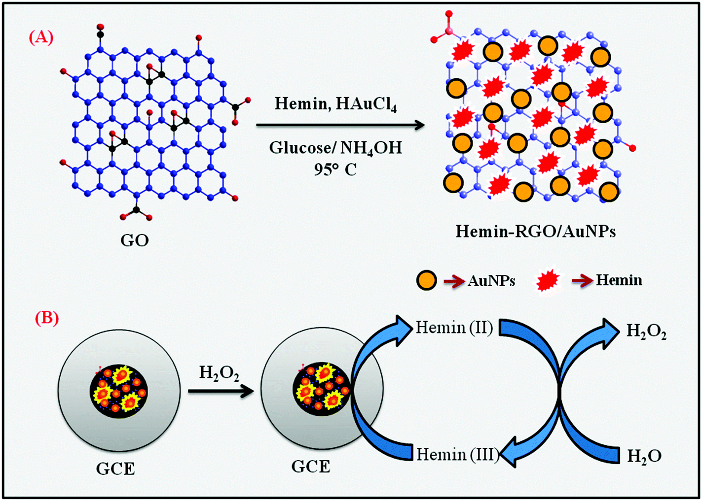 | ||
| Scheme 1 Schematic representation of the preparation of HN–RGO/AuNP composite (A) and the electrochemical pathway for H2O2 reduction (B). | ||
3. Results and discussion
3.1. Characterization of HN–RGO/AuNP composite
The surface morphologies of GO, HN, HN–RGO and HN–RGO/AuNP composites were characterized by FESEM. The typical FESEM images of GO (A), HN (B), HN–RGO (C) and HN–RGO/AuNP (D) composite are shown in Fig. S1 (ESI†). The SEM image of GO (Fig. S1A, ESI†) shows an ultra-wrinkled, thin film-like structure, which confirms that GO sheets are assembled layer-by-layer, and the SEM image of HN (Fig. S1B, ESI†) reveals a rod-like morphology. On the other hand, HN–RGO (Fig. S1C, ESI†) composite shows a crumbled morphology, further confirming that the hemin moieties were tightly aggregated on the RGO surface through strong π–π interaction, which indicates the higher surface area of HN–RGO. However, for the HN–RGO/AuNP (Fig. S1D, ESI†) composite, we observed that nanosized particles were homogeneously grown on the HN–RGO surface, indicating the presence of AuNPs that were successfully intercalated on the HN–RGO surface. The prepared HN–RGO/AuNP composite was further confirmed by TEM images as shown in Fig. 1. It can be seen that the nanosized AuNPs are uniformly covered on the surface of the HN–RGO layer. The average diameter of AuNPs on the HN–RGO surface was 68 ± 5 nm (observed from Fig. 1). In addition, the EDX elemental mapping also supports the formation of AuNPs on the HN–RGO surface. The SEM image of HN–RGO/AuNP composite (A) and corresponding elemental mapping of carbon (B), oxygen (C) and gold (D) nanoparticles are shown in Fig. S2 (ESI†).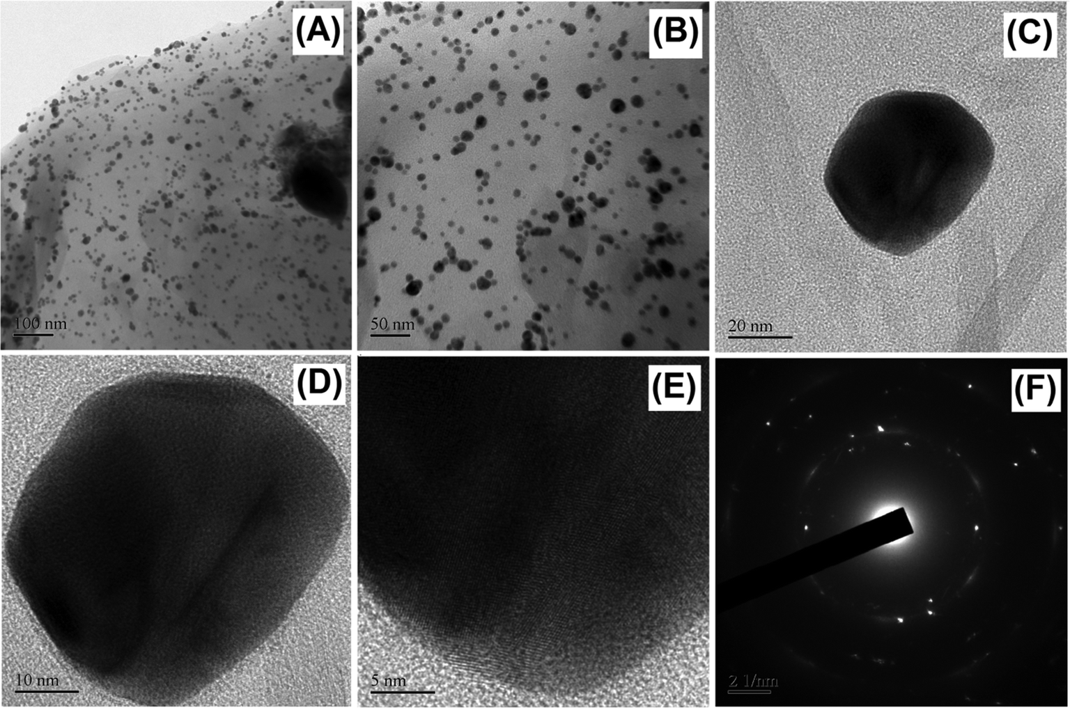 | ||
| Fig. 1 HR-TEM images of HN–RGO/AuNPs at different magnifications (A–E) and the corresponding SEAD diffraction pattern of AuNPs (F). | ||
The HN–RGO/AuNP composite was further characterized by UV-vis spectroscopy. As shown in Fig. 2A, GO (a) exhibits a maximum absorption peak at 235 nm, which is the π–π* transition of aromatic C![[double bond, length as m-dash]](https://www.rsc.org/images/entities/char_e001.gif) C bonds, and a shoulder peak at about 300 nm, belonging to the n–π* transition of CO.33 On the other hand, HN (b) shows a typical Soret absorption band at 387 nm and also a series of weak absorption bands at longer wavelengths between 500–700 nm, which indicate the presence of Q-bands of the HN moiety. The HN–RGO (c) composite displays two strong absorption peaks at 267 and 423 nm with a large bathochromic shift, which is due to interaction between the porphyrin moiety of HN and RGO through π–π stacking interactions, further confirming the formation of HN–RGO. In addition, a new absorption peak appears at 539 nm, which corresponds to the surface plasmon absorption of AuNPs on the HN–RGO surface. This result clearly indicates the formation of AuNPs that are homogeneously decorated on the HN–RGO surface.
C bonds, and a shoulder peak at about 300 nm, belonging to the n–π* transition of CO.33 On the other hand, HN (b) shows a typical Soret absorption band at 387 nm and also a series of weak absorption bands at longer wavelengths between 500–700 nm, which indicate the presence of Q-bands of the HN moiety. The HN–RGO (c) composite displays two strong absorption peaks at 267 and 423 nm with a large bathochromic shift, which is due to interaction between the porphyrin moiety of HN and RGO through π–π stacking interactions, further confirming the formation of HN–RGO. In addition, a new absorption peak appears at 539 nm, which corresponds to the surface plasmon absorption of AuNPs on the HN–RGO surface. This result clearly indicates the formation of AuNPs that are homogeneously decorated on the HN–RGO surface.
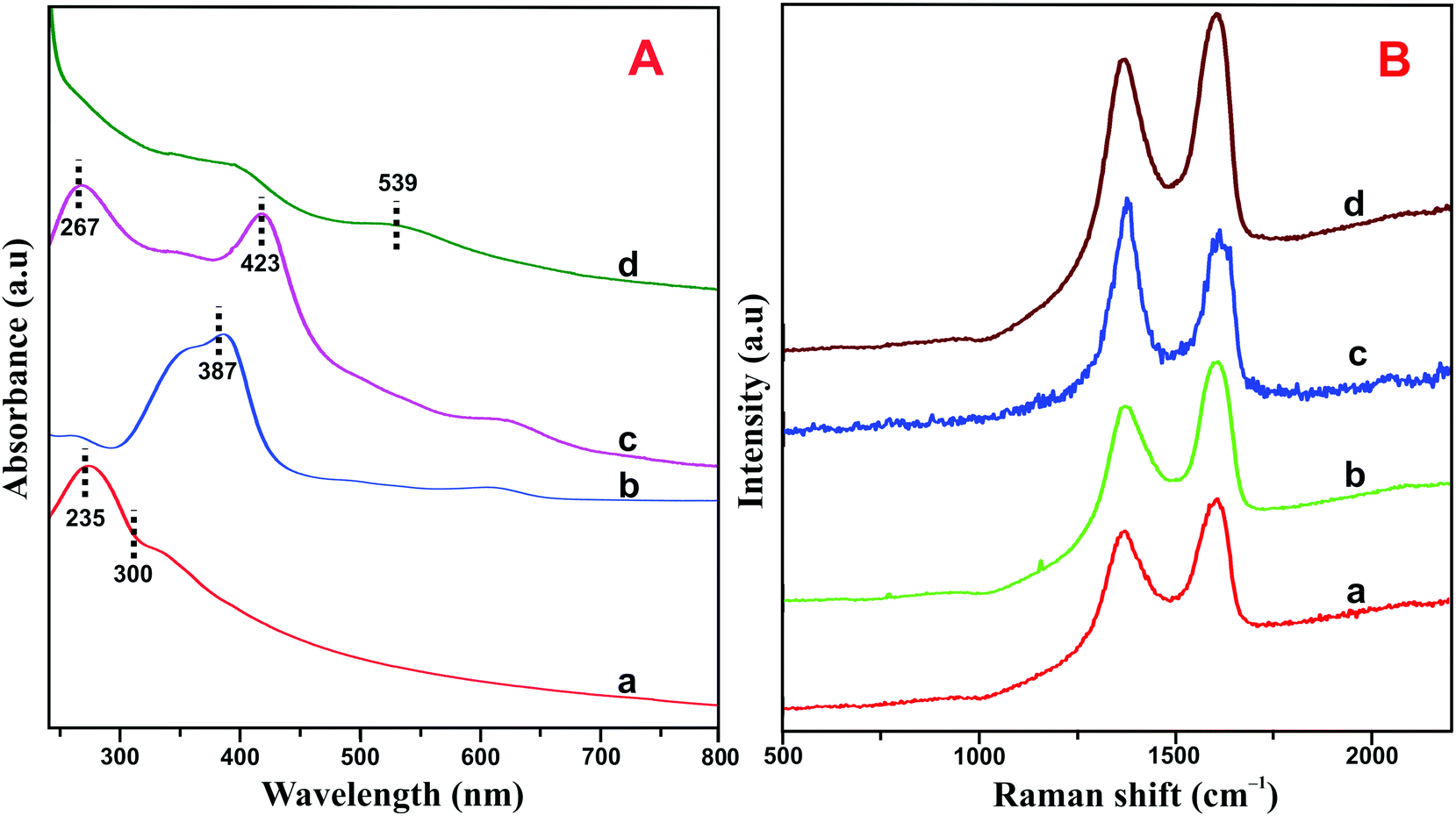 | ||
| Fig. 2 (A) UV-vis spectra of GO (a), HN (b), HN–RGO (c) and HN–RGO/AuNP (d) composite. (B) Raman spectra of GO (a), HN–GO (b), HN–RGO (c), and HN–RGO/AuNP (d) composite. | ||
The crystalline nature of graphene and hybrid nanomaterials were characterized by Raman spectroscopy. Fig. 2B depicts the Raman spectra of GO (a), HN–GO (b), HN–RGO (c) and HN–RGO/AuNP (d) composite. It can be clearly seen that GO shows two specific peaks at frequencies of 1570 and 1330 cm−1, which correspond to the sp2 carbon in pure graphite structure (G band) and sp3 carbon units of defects and disordered oxygen functionalities (D band), respectively.34,35 The calculated intensity ratio (ID/IG) values for GO, HN–GO, HN–RGO and HN–RGO/AuNP composites were 0.879, 1.221, 1.37 and 1.402, respectively. The ID/IG value of the HN–RGO/AuNP composite is much higher than those of GO, HN–GO, HN–RGO, which also confirms the formation of strong π–π interaction between the porphyrin units of HN and the graphitic units of RGO/AuNPs. This result confirms the formation of GO to RGO and that the HN molecules are successfully attached to the surface of RGO.
The HN–RGO/AuNP composite was further confirmed by XRD pattern. Fig. S3 (ESI†) shows the XRD patterns for GO (a), HN–RGO (b) and HN–RGO/AuNP (c) composite. It can be seen that GO shows two discrete 2θ peaks at 11.52 and 26.68°, apart from the 2θ peaks of ITO (21.46, 30.32, 35.12, 50.34 and 60.22°). The specific peaks are analogous to a report by Hae et al. for the hydroxyl, epoxide, and carboxyl-functionalized GO.36 According to JCPDS no. 01-088-0315, the cubic crystalline Fe2O3 shows two sharp peaks at 30.32° and 35.58°, which indicate the presence of HN due to the oxidation of Fe in HN by the trace dioxygen in the atmosphere.37 In addition, compared with GO and HN–RGO composite, two diffraction peaks were observed in HN–RGO/AuNPs, which could be indexed to the (111) and (200) planes of AuNPs, as per the JCPDS file for bulk Au,38 which strongly indicate that HN is strongly attached to RGO and that the AuNPs are decorated on the HN–RGO surface.
3.2. Electrochemical behavior of HN–RGO/AuNP-modified electrode
The electrochemical behavior of different HN-modified electrodes were investigated by CV. Fig. 3(A) shows the CV response of HN (a), HN–GO (b), HN–RGO (c) and HN–RGO/AuNP (d) modified electrodes in N2-saturated PBS at a scan rate of 100 mV s−1. A weak quasi-reversible redox peak was observed at the HN-modified electrode (a). The HN–GO-modified electrode (b) showed a weak redox peak, while a cathodic and anodic peak appeared at −0.392 and −0.321 V, respectively.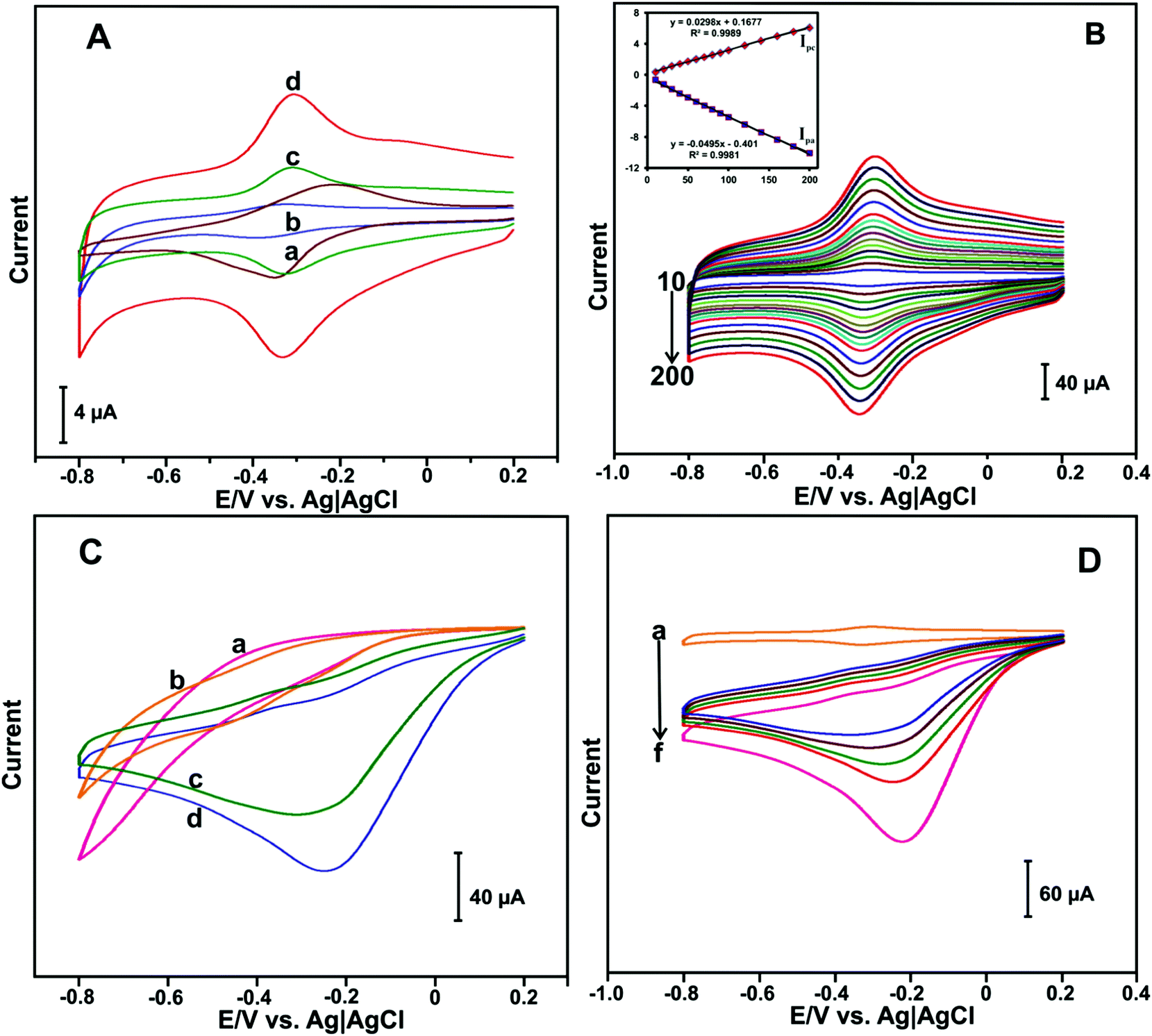 | ||
| Fig. 3 (A) CV response of HN (a), HN–GO (b), HN–RGO (c) and HN–RGO/AuNP (d) modified electrodes in N2-saturated PBS at a scan rate of 100 mV s−1. (B) CV response of HN–RGO/AuNP-modified electrode in N2-saturated PBS at scan rates from 10–200 mV s−1. Inset: The corresponding calibration plot for Ipa and Ipcvs. scan rate. (C) CV curves of HN (a), HN–GO (b), HN–RGO (c) and HN–RGO/AuNP (d) modified electrodes in 50 μM H2O2 containing N2-saturated PBS at a scan rate of 100 mV s−1. (D) CV curves of HN–RGO/AuNP-modified electrode in the absence (a) and presence of different amounts of H2O2 (10 μM (b–e), 20 μM (f)) in N2-saturated PBS at a scan rate of 100 mV s−1. | ||
On the other hand, the HN–RGO-modified electrode (c) showed a well-defined redox couple, whereas the cathodic and anodic peaks were located at −0.331 and −0.308 V, respectively. Compared with HN-, HN–GO- and H-RGO-modified electrodes, the HN–RGO/AuNP-modified electrode showed a stable and well-defined redox couple [Hemin Fe(III) ↔ Hb Fe(II)] with a formal potential (E°) of −0.317 V, while the peak-to-peak separation (ΔEp) value of 21 mV was much lower than that of other HN-modified electrodes reported earlier,39 which indicates the fast electron transfer of HN on the electrode surface.40 The fast electron transfer and excellent electrochemical behavior of HN shows its good biocompatibility in RGO/AuNPs, suggesting that the presence of AuNPs can enhance the electron transfer behavior of HN on the electrode surface.
To investigate the electrochemical behavior of the HN–RGO/AuNP-modified electrode, CV at different scan rates was performed. Fig. 3(B) shows the CV response of the HN–RGO/AuNP-modified electrode in N2-saturated PBS at different scan rates from 10–200 mV s−1. It can be seen that the redox couple of the anodic (Ipa) and cathodic (Ipc) peak current was gradually increased upon increasing the scan rate. The calibration plot of Ipa and Ipc has a linear dependence over the scan rate from 10 to 200 mV s−1, with a correlation coefficient for Ipa and Ipc of 0.9981 and 0.9989, respectively (Fig. 3B inset). Based on the redox electrochemical behavior, HN was embedded on the HN–RGO/AuNP-modified electrode by a surface-controlled process.41 The average surface coverage value of HN on the HN–RGO/AuNP-modified electrode can be calculated using the following eqn (1):
| Г = Q/nFA | (1) |
To further investigate, the electrochemical behavior of HN–RGO/AuNP-modified electrode at different pH levels was studied by CV. The protonation of heme ions depend on the solution pH. Besides, the electrochemical behavior of enzymatic biosensors generally affects the solution pH. Hence, we have studied the effect of solution pH on the HN–RGO/AuNP-modified electrode. Fig. S4(A) (ESI†) depicts the CV response obtained at the HN–RGO/AuNP-modified electrode in N2-saturated solutions with different pH values (3, 5, 7, 9 and 11) at a scan rate of 100 mV s−1. A well-defined redox couple was observed for each pH. The peak potentials (Epa and Epc) were shifted toward positive and negative directions upon increasing and decreasing the pH. The calibration plot of E° vs. pH showed a linear dependence with a slope and correlation coefficient of −52.6 mV per pH and 0.9933, respectively; the results shown in Fig. S4(B) (ESI†) indicate the electrochemical redox behavior of HN participating with equal numbers of protons (H+) and electrons (e−) in the electrochemical process.
3.3. Electrocatalytic reduction of H2O2 at the HN–RGO/AuNP-modified electrode
To investigate the electrocatalytic activity of HN–RGO/AuNP-modified electrode toward H2O2 reduction, CV was performed. The CV curves of HN (a), HN–GO (b), HN–RGO (c) and HN–RGO/AuNP (d) modified electrodes containing 50 μM H2O2 in PBS at a scan rate of 100 mV s−1 are shown in Fig. 3C. No obvious reduction peak was observed in the presence of 50 μM H2O2 at the HN- and HN–GO-modified electrodes. A weak cathodic peak was observed at −0.23 V in the presence of 50 μM H2O2 at the HN–RGO modified electrode, which indicates a typical electrocatalytic reduction of H2O2. However, a sharp cathodic peak was observed at −0.18 V on the HN–RGO/AuNP-modified electrode, which suggests that the introduction of AuNPs on HN–RGO can enhance the electrocatalytic activity with H2O2, mediated by the Fe3+/Fe2+ (HN) on the electrode surface. In addition, we have studied the effect of AuNPs on HN–RGO/AuNP composite formation for the detection of H2O2 using different concentrations of AuCl4·3H2O solution, and the results are shown in Fig. S5 (ESI†). It can be seen that the higher response current of H2O2 was observed in 0.5 mM AuCl4 solution with the HN–RGO/AuNPs composite. However, the response current rapidly decreased when the AuCl4 concentration was increased or decreased. Hence, 0.5 mM of AuCl4 solution is the optimum concentration for HN–RGO/AuNPs with the average diameter of AuNPs is 68 ± 5 nm (see Fig. 1). Moreover, the electrocatalytic activity of HN–RGO/AuNP-modified electrode towards different additions of H2O2 was studied by CV. Fig. 3(D) shows the CV response obtained at the HN–RGO/AuNP-modified electrode in the absence (a) and presence of different amounts of H2O2 (b–f) in PBS at a scan rate of 100 mV s−1. We observed a well-defined redox couple at the HN–RGO/AuNP-modified electrode in the absence of H2O2. Noticeably, the cathodic peak current gradually increases with increasing concentration of H2O2 (10 μM (b–e), 20 μM (f)), and the anodic peak decreases gradually, which reveals that the HN–RGO/AuNP-modified electrode has higher electrocatalytic activity towards H2O2. This result suggests that the HN–RGO/AuNP-modified electrode exhibits fast electron transfer and higher electrocatalytic activity towards the reduction of H2O2.3.4. Amperometric determination of H2O2
An accurate and low-level determination of H2O2 using a HN–RGO/AuNP-modified rotational disk electrode (RDE) was evaluated by amperometric method. Fig. 4(A) shows the amperometric i–t response of HN–RGO/AuNP-modified RDE to the successive additions of different concentrations of H2O2 into N2-saturated, constantly stirred PBS at an applied potential of −0.18 V. As seen from Fig. 4A, a well-defined and stable amperometric response was observed for different additions of H2O2 at the HN–RGO/AuNP-modified RDE, reaching a stable current within 3 s, which indicates fast electron transfer on the electrode surface and higher electrocatalytic activity towards H2O2 reduction. The response current of the biosensor had linear dependence on the concentrations of H2O2 ranging from 0.05 to 518.15 μM, with a sensitivity of 3.99 μA μM−1 cm−2 (Fig. 4B). The limit of detection (LOD) was calculated as 16 nM based on S/N = 3.43 The efficiency of the proposed biosensor was compared with previously reported HN-based biosensors. However, various metal nanoparticles are used for non-enzymatic H2O2 sensors. Hence, it is necessary to compare the analytical performance of the proposed biosensor with previous studies, and the results are shown in Table 1.4,25,27,28,30,50–56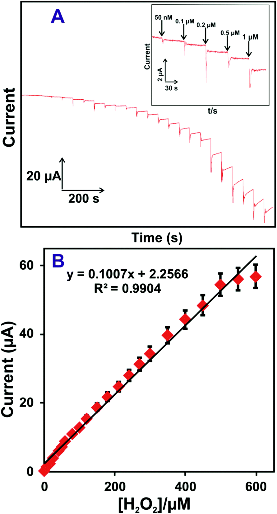 | ||
| Fig. 4 (A) Amperometric i–t response of the HN–RGO/AuNP-modified RDE to the successive additions of different concentrations of H2O2 into N2-saturated, constantly stirred PBS at an applied potential of −0.18 V. Inset: Enlarged view of Fig. 4A. (B) Calibration plot for cathodic peak current vs. [H2O2]; the error bar indicates the standard deviation of three measurements. | ||
| Modified electrodes | Detection limit (μM) | Applied potential (V) vs. Ag|AgCl | Linear range (μM) | Ref. |
|---|---|---|---|---|
| Abbreviations: GNs-graphene nanosheets, OMC-ordered mesoporous carbon, PPY-polypyrrole, PEDOT-poly(3,4-dioxyethylenethiophene), SWCNT-single-walled carbon nanotube, AuNPs-gold nanoparticles, RGO-reduced graphene oxide, GCE-glassy carbon electrode, AgNPs-silver nanoparticles, PANINFs-polyaniline nanofibers, AuPs-gold nanoplates, PPyC-polypyrrole colloids. | ||||
| Hemin–graphene–PEDOT/GCE | 0.08 | −0.2 | 0.5–70 | 4 |
| Hemin–GNs/GCE | 0.20 | −0.2 | 0.5–400 | 25 |
| RGO–hemin–Au/GCE | 0.03 | −0.18 | 0.1–40 | 27 |
| Hemin–GNs–AuNPs/GCE | 0.11 | −0.2 | 0.3–1800 | 28 |
| GN–hemin–SWCNT/GCE | 0.05 | −0.2 | 0.2–400 | 30 |
| Hemin–OMC–nafion/GCE | 0.3 | −0.4 | 2–250 | 50 |
| PPY–hemin–RGO/GCE | 0.13 | −0.15 | 0.5–80 | 51 |
| AgNPs/PANINFs/GCE | 1.7 | −0.3 | 100–60![[thin space (1/6-em)]](https://www.rsc.org/images/entities/char_2009.gif) 000 000 |
52 |
| AuNPs/GCE | 4.0 | −0.3 | 100–50000 |
53 |
| AgNPs–RGO/GCE | 1.8 | −0.3 | 100–60000 |
54 |
| AgNP–PPyC/GCE | 1.05 | −0.3 | 100–90000 |
55 |
| Ag/GN/GCE | 28 | −0.4 | 100–40000 |
56 |
| HN–RGO/AuNPs/GCE | 0.016 | −0.18 | 0.05–518.15 | This work |
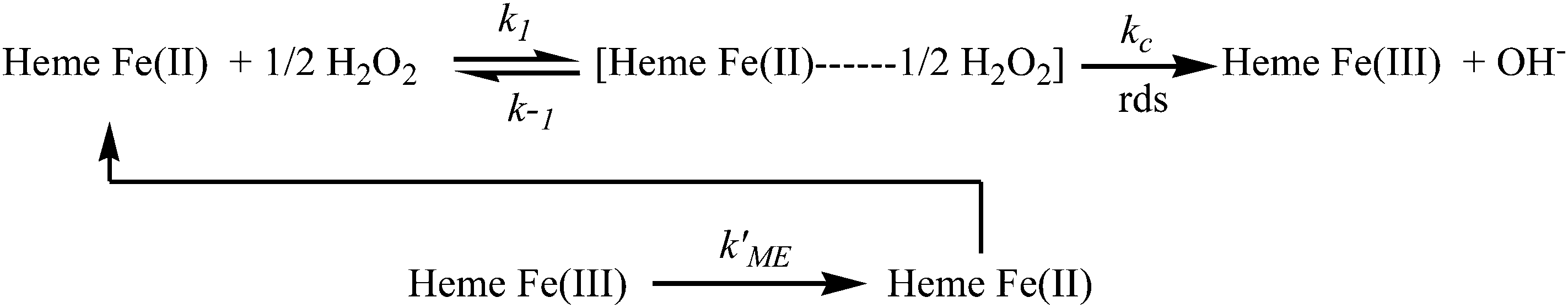
Moreover, the resultant current was deviated linearly towards H2O2 concentrations (Fig. 4B), which revealed that the kinetics of the electrocatalytic process follows the Michaelis–Menten (MM) model. The possible mechanism of the MM reaction pathway for H2O2 is given below:44–46
3.5. Selectivity, stability, repeatability and reproducibility
The selectivity, stability, repeatability and reproducibility of the H2O2 biosensor are more important for practical applications. Fig. 5(A) depicts the amperometric i–t responses obtained at the HN–RGO/AuNP-modified RDE for the successive addition of 5 μM H2O2 (a) and 100 μM of DA (b), AA (c), UA (d), melatonin (e), EP (f), NEP (g) and glucose (h) into constantly stirred, N2-saturated PBS at −0.18 V.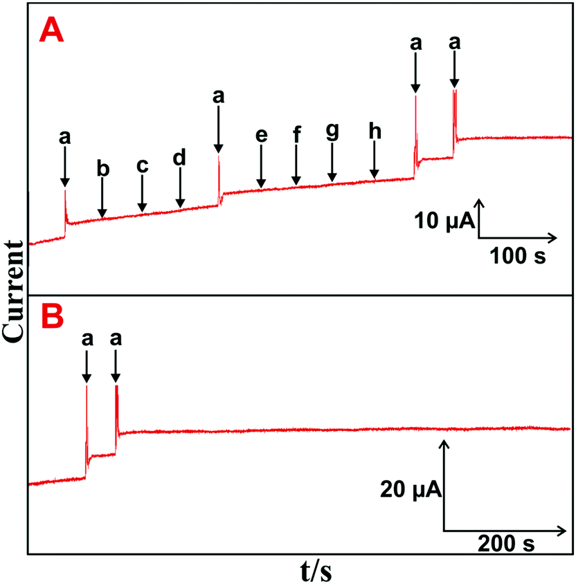 | ||
| Fig. 5 (A) Amperometric i–t response of HN–RGO/AuNP-modified RDE to the addition of 5 μM H2O2 (a) and 100 μM of DA (b), AA (c), UA (d), melatonin (e), EP (f), NEP (g) and glucose (h) into constantly stirred, N2-saturated PBS. (B) Amperometric i–t response of the HN–RGO/AuNP-modified RDE to the addition of 5 μM H2O2 (a) into N2-saturated, constantly stirred PBS for up to 1800 s. | ||
A stable and sharp amperometric response current was observed with the addition of 5 μM H2O2, while no obvious response was observed for H2O2 with a sequential addition of the abovementioned biological interfering species, suggesting that the biosensor was highly active and selective for H2O2 detection. Moreover, the CV response for continuous cycling (n = 25) of the HN–RGO/AuNP-modified electrode in N2-saturated PBS at a scan rate of 100 mV s−1 was measured. No change in the redox behavior was seen, and it did not show any alternate change in peak current and peak potential (figure not shown), implying an appreciable stability of the HN–RGO/AuNPs. The operational stability of HN–RGO/AuNP-modified RDE for 5 μM H2O2 was investigated by amperometry, and the results are shown in Fig. 5(B). The other experimental conditions are similar as shown in Fig. 4A. The biosensor retains 98.9% of its initial amperometric response with the addition of 5 μM H2O2 containing N2-saturated, constantly stirred PBS for up to 1800 s. The results validate the higher operational stability of the biosensor towards H2O2. The repeatability of the biosensor was evaluated for the determination H2O2 with a relative standard deviation (RSD) of 2.8% for 10 successive measurements. This result suggests that the HN–RGO/AuNP-modified electrode exhibits a highly stable and sensitive detection of H2O2 for practical applications.
3.6. Real sample analysis
The practical application of the biosensor was studied in real sample analysis using amperometry. Human blood serum, contact lens solution and milk samples containing H2O2 were tested by standard addition method. The samples were diluted with PBS, and samples containing known concentrations of H2O2 were spiked into PBS. The experimental conditions are similar in Fig. 4A. The recovery values are shown in Table 2. The recovery values remained approximately 100%. This result authenticates the practicality of the proposed biosensor for the detection of H2O2 in real samples for biological applications.| Sample | Spiked (μM) | Found (μM) | Recovery (%) | RSD (%) |
|---|---|---|---|---|
| Human serum | 0.5 | 0.47 | 94.0 | 2.6 |
| 0.5 | 0.49 | 98.0 | 2.8 | |
| Contact lens solution | 0.5 | 0.49 | 98.0 | 3.2 |
| 0.5 | 0.51 | 102.0 | 3.4 | |
| Milk sample | 0.5 | 0.53 | 106.0 | 3.9 |
| 0.5 | 0.51 | 102.0 | 3.7 | |
4. Conclusions
In conclusion, we reported a one-pot synthesis of a highly stable, supported biomolecule, the HN–RGO/AuNP-composite, for use as a high-performance H2O2 biosensor. The HN–RGO/AuNP-modified electrode showed excellent electrocatalytic activity such as higher sensitivity, stability, and fast response towards the reduction of H2O2 compared to that of other HN-modified electrodes. The biosensor exhibited excellent amperometric response towards H2O2 in PBS with common interfering biological molecules such as a DA, AA, UA, melatonin, EP, NEP and glucose. The electrochemical results suggested that the biosensor has higher sensitivity, stability and lower LOD (16 nM) towards H2O2. We have successfully demonstrated the detection of H2O2 in real sample analysis with good average recovery of ∼100%. We believe that the biosensor could be used for biomedical, biological and electronic biosensor devices in the future.Acknowledgements
This project was supported by the Ministry of Science and Technology (NSC101-2113-M-027-001-MY3), Taiwan (Republic of China).References
- H. Wei and E. Wang, Anal. Chem., 2008, 80, 2250–2254 CrossRef CAS PubMed.
- T. Xue, S. Jiang, Y. Qu, Q. Su, R. Cheng, S. Dubin, C. Y. Chiu, R. Kaner, Y. Huang and X. Duan, Angew. Chem., Int. Ed. Engl., 2012, 51, 3822–3825 CrossRef CAS PubMed.
- Z. Genfa and P. K. Dasgupta, Anal. Chem., 1992, 64, 517–522 CrossRef CAS PubMed.
- W. Lei, L. Wu, W. Huang, Q. Hao, Y. Zhang and X. Xia, J. Mater. Chem. B, 2014, 2, 4324–4330 RSC.
- F. T. Zhang, X. Long, D. W. Zhang, Y. L. Sun, Y. L. Zhou, Y. R. Ma, L. M. Qi and X. X. Zhang, Sens. Actuators, B, 2014, 192, 150–156 CrossRef CAS.
- T. Kuila, A. K. Mishra, P. Khanra, N. H. Kim and J. H. Lee, Nanoscale, 2013, 5, 52–71 RSC.
- Y. Shao, J. Wang, H. Wu, J. Liu, I. A. Aksay and Y. Lin, Electroanalysis, 2010, 22, 1027–1036 CrossRef CAS.
- K. S. Novoselov, A. K. Geim, S. V. Morozov, D. Jiang, Y. Zhang, S. V. Dubonos, I. V. Grigorieva and A. A. Firsov, Science, 2004, 306, 666–669 CrossRef CAS PubMed.
- J. Du, X. Lai, N. Yang, J. Zhai, D. Kisailus, F. Su, D. Wang and L. Jiang, ACS Nano, 2011, 5, 590–596 CrossRef CAS PubMed.
- M. A. Rafiee, J. Rafiee, Z. Wang, H. Song, Z. Z. Yu and N. Koratkar, ACS Nano, 2009, 3, 3884–3890 CrossRef CAS PubMed.
- B. Thirumalraj, S. Palanisamy, S. M. Chen and B. S. Lou, J. Colloid Interface Sci., 2016, 462, 375–381 CrossRef CAS PubMed.
- R. Oprea, S. F. Peteu, P. Subramanian, W. Qi, E. Pichonat, H. Happy, M. Bayachou, R. Boukherroub and S. Szunerits, Analyst, 2013, 138, 4345–4352 RSC.
- X. Zhu, Q. Liu, X. H. Zhu, C. Li, M. T. Xu and Y. Liang, Int. J. Electrochem. Sci., 2012, 7, 5172–5184 CAS.
- I. Kaminska, M. R. Das, Y. Coffinier, J. N. Jonsson, P. Woisel, M. Opallo, S. Szunerits and R. Boukherroub, Chem. Commun., 2012, 48, 1221–1223 RSC.
- A. Tao, P. Sinsermsuksakul and P. D. Yang, Nat. Nanotechnol., 2007, 2, 435–440 CrossRef CAS PubMed.
- B. Kong, A. Zhu, Y. Luo, Y. Tian, Y. Yu and G. Shi, Angew. Chem., 2011, 123, 1877–1880 CrossRef.
- X. H. Huang, I. H. El-Sayed, W. Qian and M. A. El-Sayed, Nano Lett., 2007, 7, 1591–1597 CrossRef CAS PubMed.
- M. Schrinner, M. Ballauff, Y. Talmon, Y. Kauffmann, J. Thun, M. Möller and J. Breu, Science, 2009, 323, 617–620 CrossRef CAS PubMed.
- S. Liu, J. Tian, L. Wang, Y. Luo, W. Lu and X. Sun, Biosens. Bioelectron., 2011, 26, 4491–4496 CrossRef CAS PubMed.
- S. Palanisamy, B. Thirumalraj and S. M. Chen, RSC Adv., 2015, 5, 94591–94598 RSC.
- F. Y. Kong, Z. Xu, M. T. Xu, J. J. Xu and H. Y. Chen, Electrochim. Acta, 2011, 56, 9386–9390 CrossRef CAS.
- W. Chen, S. Cai, Q. Q. Ren, W. Wen and Y. D. Zhao, Analyst, 2012, 137, 49–58 RSC.
- S. Palanisamy, H. F. Lee, S. M. Chen and B. Thirumalraj, RSC Adv., 2015, 5, 105567 RSC.
- Y. Guo, L. Deng, J. Li, S. Guo, E. Wang and S. Dong, ACS Nano, 2011, 5, 1282–1290 CrossRef CAS PubMed.
- Y. Guo, J. Li and S. Dong, Sens. Actuators, B, 2011, 160, 295–300 CrossRef CAS.
- R. Jiang, D. T. Tran, J. McClure and D. Chu, Electrochem. Commun., 2012, 19, 73–76 CrossRef CAS.
- C. J. Gu, F. Y. Kong, Z. D. Chen, D. H. Fan, H. L. Fang and W. Wang, Biosens. Bioelectron., 2016, 78, 300–307 CrossRef CAS PubMed.
- H. Song, Y. Ni and S. Kokot, Anal. Chim. Acta, 2013, 788, 24–31 CrossRef CAS PubMed.
- J. Chen, L. Zhao, H. Bai and G. Shi, J. Electroanal. Chem., 2011, 657, 34–38 CrossRef CAS.
- F. Y. Kong, W. W. Li, J. Y. Wang, H. L. Fang, D. H. Fan and W. Wang, Anal. Chim. Acta, 2015, 884, 37–43 CrossRef CAS PubMed.
- H. L. Zou, B. L. Li, H. Q. Luo and N. B. Li, Sens. Actuators, B, 2015, 207, 535–541 CrossRef CAS.
- W. S. Hummers and R. E. Offeman, J. Am. Chem. Soc., 1958, 80, 1339 CrossRef CAS.
- D. Li, M. B. Mueller, S. Gilje, R. B. Kaner and G. G. Wallace, Nat. Nanotechnol., 2008, 3, 101–105 CrossRef CAS PubMed.
- S. Stankovich, D. A. Dikin, R. D. Piner, K. A. Kohlhaas, A. Kleinhammes, Y. Jia, Y. Wu, S. T. Nguyen and R. S. Ruoff, Carbon, 2007, 45, 1558–1565 CrossRef CAS.
- I. Calizo, A. A. Balandin, W. Bao, F. Miao and C. N. Lau, Nano Lett., 2007, 7, 2645–2649 CrossRef CAS PubMed.
- K. J. Hae, P. L. Yun, H. J. Mei, S. K. Eun, J. B. Jung and H. L. Young, Chem. Phys. Lett., 2009, 470, 255–258 CrossRef.
- Q. Wang, Z. Zhou, D. Chen, J. Lin, F. Ke, G. Xu and S. Sun, Sci. China: Chem., 2010, 53, 2057–2062 CrossRef CAS.
- J. Zhang, X. Liu, L. Wang, T. Yang, X. Guo, S. Wu, S. Zhang and S. Wang, Carbon, 2011, 49, 3538–3543 CrossRef CAS.
- Q. Ma, S. Ai, H. Yin, Q. Chen and T. Tang, Electrochim. Acta, 2010, 55, 6687–6694 CrossRef CAS.
- G. Q. Shi and H. Ohno, J. Electroanal. Chem., 1991, 314, 59–69 CrossRef CAS.
- A. J. Bard and L. R. Faulkner, ISBN: 978-0-471-04372-0.
- J. Chen, U. Wollenberger, F. Lisdat, B. Ge and F. W. Scheller, Sens. Actuators, B, 2000, 70, 115–120 CrossRef CAS.
- V. Mani, B. Dinesh, S. M. Chen and R. Saraswathi, Biosens. Bioelectron., 2014, 53, 420–427 CrossRef CAS PubMed.
- M. E. G. Lyons, C. A. Fitzgerald and M. R. Smyth, Analyst, 1994, 119, 855–861 RSC.
- R. A. Kamin and G. S. Wilson, Anal. Chem., 1980, 52, 1198–1205 CrossRef CAS.
- A. S. Kumar, P. Barathi and K. C. Pillai, Colloids Surf., A, 2012, 395, 207–216 CrossRef.
- K. P. Lee, A. I. Gopalan and S. Komathia, Sens. Actuators, B, 2009, 141, 518–525 CrossRef CAS.
- A. S. Kumar, P. Gayathri, P. Barathi and R. Vijayaraghavan, J. Phys. Chem. C, 2012, 116, 23692–23703 Search PubMed.
- X. Lv and J. Weng, Sci. Rep., 2013, 3, 3285–3295 Search PubMed.
- H. Cao, X. Sun, Y. Zhang, C. Hu and N. Jia, Anal. Methods, 2012, 4, 2412–2416 RSC.
- W. Huang, Q. Hao, W. Lei, L. Wu and X. Xia, Mater. Res. Express, 2014, 1, 045601 CrossRef.
- G. Chang, Y. Luo, W. Lu, X. Qin, A. M. Asiri, A. O. Al-Youbi and X. Sun, Catal. Sci. Technol., 2012, 2, 800–806 CAS.
- R. Ning, W. Lu, Y. Zhang, X. Qin, Y. Luo, J. Hu, A. M. Asiri, A. O. Al-Youbi and X. Sun, Electrochim. Acta, 2012, 60, 13–16 CrossRef CAS.
- X. Qin, Y. Luo, W. Lu, G. Chang, A. M. Asiri, A. O. Al-Youbi and X. Sun, Electrochim. Acta, 2012, 79, 46–51 CrossRef CAS.
- X. Qin, W. Lu, Y. Luo, G. Chang and X. Sun, Electrochem. Commun., 2011, 13, 785–787 CrossRef CAS.
- S. Liu, J. Tian, L. Wang, H. Li, Y. Zhang and X. Sun, Macromolecules, 2010, 43, 10078–10083 CrossRef CAS.
Footnote |
| † Electronic supplementary information (ESI) available. See DOI: 10.1039/c6tb01576j |
| This journal is © The Royal Society of Chemistry 2016 |