 Open Access Article
High performance Pt-free cathode catalysts for polymer electrolyte membrane fuel cells prepared from widely available chemicals†
Yuta
Nabae
*a,
Yongbo
Kuang
a,
Masayuki
Chokai
b,
Takeo
Ichihara
c,
Ayano
Isoda
d,
Teruaki
Hayakawa
a and
Tsutomu
Aoki
d
aDepartment of Organic and Polymeric Materials, Tokyo Institute of Technology, 2-12-1 S8-26 Ookayama, Meguro-ku, Tokyo 152-8552, Japan. E-mail: nabae.y.aa@m.titech.ac.jp; Fax: +81 3 5734 2433; Tel: +81 3 5734 2429
bIntegrative Technology Research Institute, Teijin Ltd., 4-3-2, Asahigaoka, Hino, Tokyo 191-8512, Japan
cAsahi Kasei Chemicals Corporation, 2767-11 Niihama, Shionasu, Kojima, Kurashiki-shi, Okayama 711-8510, Japan
dToshiba Fuel Cell Power Systems Corporation, 4-1, Ukishima-cho, Kawasaki-ku, Kawasaki-shi, Kanagawa 210-0862, Japan
First published on 20th May 2014
Abstract
A high performance Pt-free cathode catalyst for polymer electrolyte fuel cells has been synthesized by the multi-step pyrolysis of polyimide fine particles with a diameter of about 100 nm. This cathode catalyst exhibits good fuel cell performance (1.0 A cm−2 at 0.6 V and 80 °C) along with promising durability.
Polymer electrolyte fuel cells (PEFCs) have received a great deal of attention in terms of applications in transportation, portable devices and combined heat and power systems based on their high energy conversion efficiency and scalability. One major problem for PEFCs in commercial applications is the cost and scarcity of platinum, which has been thought to be essential for the cathode catalyst for the oxygen reduction reaction (ORR). Thus, it is extremely important to develop non-precious metal (NPM) cathode catalysts.
Since Jasinski discovered the catalytic activity of Co phthalocyanine1 for ORR and Jahnke reported the heat treatment of Co TAA (Co dibenzotetraazaannulene),2 numerous attempts have been made to develop NPM cathode catalysts by pyrolyzing precursors containing transition metals (mainly Fe or Co), a nitrogen source and a carbon source.3–14 Although several potential NPM catalysts have shown quite promising fuel cell performance, the catalytic activity and durability must be further improved for commercialization.9,12,14 According to recently published reports, one important factor to achieve extremely high fuel cell performance is control of the morphology of the prepared NMP catalysts. For instance, a state-of-the-art NPM catalyst by Dodelet et al. employs metal–organic-frameworks such as a zeolitic imidazolate framework (ZIF) and has successfully obtained relatively large Brunauer–Emmett–Teller (BET) and mesopore surface areas: over 950 and 180 m2 g−1, respectively.14 However, ZIFs are very expensive materials. Therefore, exploring more cost effective approaches is quite important to consider NMP catalysts as a commercially viable material.
Our research group has been developing NPM cathode catalysts based on the multi-step pyrolysis of polymer precursors such as phenolic resin15–17 and nitrogen containing polymers.18 Specifically, our research group is now interested in infusible polymers such as polyimides. Polyimide is a thermoresistive polymer and the morphology of its precursor can be retained even after carbonization; therefore, a fine morphology can be expected compared to the polymer from phenolic resin.18 Additionally, polyimide has been widely used in the current industry as a super engineering plastic and its precursors are widely available for commercialization. This paper describes the details of NPM catalyst preparation from ordinary chemicals, pyromellitic acid dianhydride (PMDA) and 4,4′-oxydianiline (ODA), which are the most common polyimide precursors.
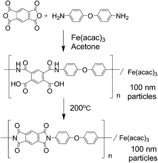
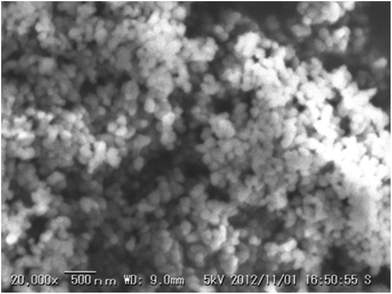
Fig. 1 shows a schematic of the synthesis of polyimide fine particles in this study. Although there have been several reports on size-controlled polyimide synthesis,19,20 most of them resulted in larger particle sizes than those desired as fuel cell catalysts. Therefore, the polymerization conditions were optimized to obtain fine polyimide particles before investigating their pyrolysis (see Fig. S1 and S2†). The important step to achieve small particle size is to enhance precipitation before the polymer grows too much by maintaining a fairly low temperature and a high concentration of the monomer. Fig. 2 shows a SEM image of the polyimide fine particles containing Fe species prepared under the optimized conditions: 0.05 M of monomer at 0 °C. The particle size of the prepared polyimide is around 100 nm. FT-IR spectra of the prepared polymers before and after the curing were measured to confirm the formation of polyimide (see Fig. S3†). Poly(amic acid) derived peaks at 1413 (C![[double bond, length as m-dash]](https://www.rsc.org/images/entities/char_e001.gif) O, acid), 1532 (C–N–H) and 1665 cm−1 (C
O, acid), 1532 (C–N–H) and 1665 cm−1 (C![[double bond, length as m-dash]](https://www.rsc.org/images/entities/char_e001.gif) O, amide) disappeared and polyimide derived peaks at 1378 (C–N–C) and 1726 (C
O, amide) disappeared and polyimide derived peaks at 1378 (C–N–C) and 1726 (C![[double bond, length as m-dash]](https://www.rsc.org/images/entities/char_e001.gif) O) appeared.21 Based on these experimental results, it can be concluded that Fe containing polyimide fine particles of around 100 nm have been successfully synthesized by the precipitation polymerization method.
O) appeared.21 Based on these experimental results, it can be concluded that Fe containing polyimide fine particles of around 100 nm have been successfully synthesized by the precipitation polymerization method.
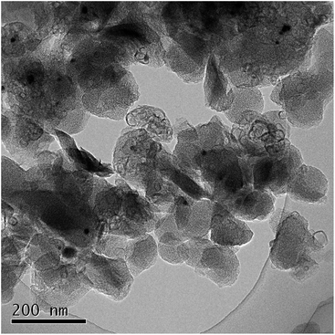
Thus obtained Fe containing polyimide fine particles were converted into carbon-based catalysts by multi-step pyrolysis.17 First, Fe/PI-600-I-N2 was prepared by single step pyrolysis of the Fe containing polyimide at 600 °C. Next, Fe/PI-800-II-NH3 was prepared by pyrolyzing Fe/PI-600-I-N2 at 800 °C under an NH3 flow (50%). Finally, Fe/PI-1000-III-NH3 was prepared by pyrolyzing Fe/PI-800-II-NH3 at 1000 °C under an NH3 flow (50%). Acid washing with HCl was carried out after the first and second pyrolysis steps. Fig. 3 shows the XRD patterns of the catalysts prepared by different pyrolysis protocols. Fe/PI-600-I-N2 shows small diffraction peaks due to metallic Fe and Fe3C. This suggests that the Fe species in the precursor mixture has been reduced to form metallic Fe and Fe3C. These diffraction peaks were also detected in Fe/PI-800-II-NH3 and Fe/PI-1000-III-NH3. As to the degree of carbonization, the diffraction peak at around 25.8° due to turbostratic carbon became sharper as the final treatment temperature became higher. Fig. 4 shows the TEM image of Fe/PI-1000-III-NH3. The particle size of the prepared carbon is around 100 nm, suggesting that the morphology of the polyimide fine particles was successfully retained even after the multi-step pyrolysis. Several dark spots in the image are probably due to the metallic Fe and Fe3C, as observed in the XRD pattern. These Fe particles presumably catalyze the formation of the layered structure.22Table 1 summarizes the elemental compositions and specific surface areas of the catalysts prepared by different pyrolysis protocols. The nitrogen content of Fe/PI-600-I-NH3 was 6.5 wt%. One might predict that the nitrogen content would significantly decrease after the treatment at higher temperatures; however, those in Fe/PI-800-II-NH3 and Fe/PI-1000-III-NH3 are not very low. This relatively high nitrogen content is likely due to the multi-step pyrolysis, which combines step-wise heat treatments and acid washing to minimize the loss of nitrogen species during the heat treatment.17 As to the Fe content, a small wt% of Fe species was detected in all samples. The BET surface area (ABET) and mesopore surface area (Ameso) of Fe/PI-1000-III-NH3 and Fe/PI-800-II-NH3 are higher than those of Fe/PI-600-I-N2. This is likely due to an etching effect by the ammonia treatment.12
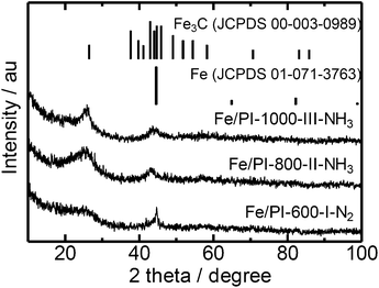 | ||
| Fig. 3 XRD patterns of the polyimide derived carbon catalysts prepared by different pyrolysis protocols. | ||
| Sample name | Elemental analysis (wt%) | EPMA Fe (wt%) | Specific surface area (m2 g−1) | |||
|---|---|---|---|---|---|---|
| C | H | N | A BET | A meso | ||
| Fe/PI-600-I-N2 | 81.0 | 1.0 | 6.5 | 2.2 | 567 | 56 |
| Fe/PI-800-II-NH3 | 82.4 | 0.2 | 7.5 | 3.6 | 899 | 96 |
| Fe/PI-1000-III-NH3 | 90.6 | Trace | 3.1 | 1.1 | 1050 | 206 |
Fig. 5 shows rotating disk electrode (RDE) voltammograms with the Fe/PI-600-I-N2, Fe/PI-800-II-NH3 and Fe/PI-1000-III-NH3 catalysts. Compared to Fe/PI-600-I-N2, the catalysts from the multi-step pyrolysis exhibited better ORR activities after further heat treatments at higher temperatures under NH3 flows. This is attributed to the ammonia treatment, which contributes to retaining a relatively high nitrogen content and increases the surface area. The catalytic performance of Fe/PI-1000-III-NH3 is better than the performance of that prepared from a different precursor, a mixture of Fe phthalocyanine and phenolic resin, but with a similar pyrolysis protocol.17 These results suggest that the polyimide fine particles are promising precursors for the preparation of NPM cathode catalysts.
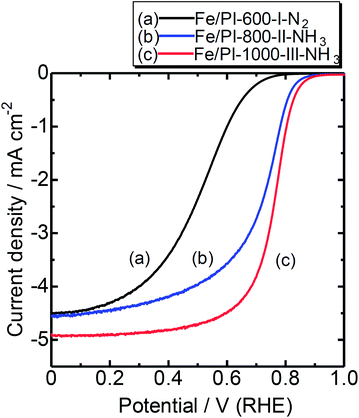 | ||
| Fig. 5 RDE voltammograms of catalysts prepared by different pyrolysis protocols. Temperature: RT; catalyst loading: 0.2 mg cm−2; electrolyte: 0.5 M H2SO4; rotation: 1500 rpm. | ||
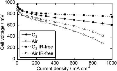
Since the Fe/PI-1000-III-NH3 sample showed the best ORR current by RDE voltammetry, this catalyst was tested in real fuel cells. Fig. 6 shows I–V performance curves of the MEA prepared using Fe/PI-1000-III-NH3 as the cathode catalyst. The open circuit voltages were 0.96 and 0.89 V with O2 and air, respectively. The current density with O2 reached 1.0 A at 0.61 V and 0.76 in the measured and IR-free voltammograms, respectively. This fuel cell performance is at a similar level to that of the state-of-the-art NPM catalyst14 while the current material can be prepared from widely available precursors, PMDA and ODA. The performance with air on the cathode side is lower than that with O2; however, it also seems promising.
Durability tests of these fuel cells were carried out by introducing air into the cathode compartment and keeping the current density at 250 or 30 mA cm−2 (Fig. 7). The best durability in the present study was obtained with 30 mA cm−2 of current density. The decrease of cell voltage after 1000 h is below 15%. To the best of our knowledge, none of the reported catalysts has demonstrated such a long-term durability and most state-of-the-art NPM catalysts significantly degrade within 100 h under real fuel cell conditions.14 However, if a higher current density, 250 mA cm−2, was applied, the cell voltage degraded more quickly, suggesting that further improvement is required to consider this class of catalysts as commercial catalysts. In the present stage, we have not clarified the detailed mechanism of the degradation. This might derive from the decomposition of active sites due to corrosion or damage of the Nafion membrane and/or binder due to H2O2 formation. The damage by H2O2 would be overcome if one could find an appropriate additive as a radical scavenger, as demonstrated by durability studies on electrolyte membranes.23,24
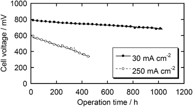 | ||
| Fig. 7 Durability tests of the MEA with the Fe/PI-1000-III-NH3 catalyst. Cathode – air: 0.2 MPa. Anode – H2: 0.2 MPa. | ||
Conclusions
A high performance Pt-free cathode catalyst for PEFCs has been synthesized by the multi-step pyrolysis of polyimide fine particles. An Fe containing polyimide with a particle size around 100 nm has been successfully converted into a Pt-free cathode catalyst material. A fuel cell utilizing the prepared catalyst shows quite promising fuel cell performance: 1.0 A cm−2 at 0.6 V and 80 °C. This fuel cell performance is at a similar level to the state-of-the-art Pt-free catalyst, and the present study reveals that high performance Pt-free catalysts can be prepared from quite ordinary chemicals, PMDA and ODA, which are the most common precursors for polyimide in the current industry. Durability tests over hundreds of hours have been completed and show fairly good stability, although further improvement is required to consider this class of catalyst for commercialization.Acknowledgements
This study was financially supported by the New Energy and Industrial Technology Development Organization (NEDO). The EPMA and TEM measurements were carried out in the Center for Advanced Materials Analysis in Tokyo Institute of Technology. The authors thank Chiharu Yamauchi, Yo Hosaka, Mayu Sonoda, Kimie Kuba and Shinsuke Nagata for technical assistance.Notes and references
- R. Jasinski, Nature, 1964, 201, 1212 CrossRef CAS.
- H. Jahnke, M. Schönborn and G. Zimmermann, Top. Curr. Chem., 1976, 61, 133 CrossRef CAS.
- G. Faubert, G. Lalande, R. Cote, D. Guay, J. P. Dodelet, L. T. Weng, P. Bertrand and G. Denes, Electrochim. Acta, 1996, 41, 1689 CrossRef CAS; G. Lalande, G. Faubert, R. Cote, D. Guay, J. P. Dodelet, L. T. Weng and P. Bertrand, J. Power Sources, 1996, 61, 227 CrossRef; M. Lefevre, J. P. Dodelet and P. Bertrand, J. Phys. Chem. B, 2002, 106, 8705 CrossRef.
- J. A. R. van Veen, H. A. Colijn and J. F. van Baar, Electrochim. Acta, 1988, 33, 801 CrossRef CAS.
- H. Schulenburg, S. Stankov, V. Schunemann, J. Radnik, I. Dorbandt, S. Fiechter, P. Bogdanoff and H. Tributsch, J. Phys. Chem. B, 2003, 107, 9034 CrossRef CAS.
- S. Maldonado and K. J. Stevenson, J. Phys. Chem. B, 2004, 108, 11375 CrossRef CAS.
- A. Widelov, Electrochim. Acta, 1993, 38, 2493 CrossRef CAS.
- V. Nallathambi, J. W. Lee, S. P. Kumaraguru, G. Wu and B. N. Popov, J. Power Sources, 2008, 183, 34 CrossRef CAS PubMed.
- G. Wu, K. L. More, C. M. Johnston and P. Zelenay, Science, 2011, 332, 443 CrossRef CAS PubMed.
- M. Bron, J. Radnik, M. Fieber-Erdmann, P. Bogdanoff and S. Fiechter, J. Electroanal. Chem., 2002, 535, 113 CrossRef CAS.
- R. Z. Yang, K. Stevens, A. Bonakdarpour and J. R. Dahn, J. Electrochem. Soc., 2007, 154, B893 CrossRef CAS PubMed.
- M. Lefevre, E. Proietti, F. Jaouen and J. P. Dodelet, Science, 2009, 324, 71 CrossRef CAS PubMed.
- P. H. Matter, L. Zhang and U. S. Ozkan, J. Catal., 2006, 239, 83 CrossRef CAS PubMed; P. H. Matter, E. Wang, M. Arias, E. J. Biddinger and U. S. Ozkan, J. Mol. Catal. A: Chem., 2007, 264, 73 CrossRef PubMed.
- E. Proietti, F. Jaouen, M. Lefevre, N. Larouche, J. Tian, J. Herranz and J. P. Dodelet, Nat. Commun., 2011, 2, 416 CrossRef PubMed.
- H. Niwa, M. Saito, M. Kobayashi, Y. Harada, M. Oshima, S. Moriya, K. Matsubayashi, Y. Nabae, S. Kuroki, T. Ikeda, K. Terakura, J. Ozaki and S. Miyata, J. Power Sources, 2013, 223, 30 CrossRef CAS PubMed.
- C. W. Chang, Y. Nabae, S. Kuroki, T. Hayakawa, M. Kakimoto and S. Miyata, Chem. Lett., 2012, 41, 923 CrossRef CAS.
- Y. Nabae, M. Sonoda, C. Yamauchi, Y. Hosaka, A. Isoda and T. Aoki, Catal. Sci. Technol., 2014, 4, 1400 CAS.
- M. Chokai, M. Taniguchi, S. Moriya, K. Matsubayashi, T. Shinoda, Y. Nabae, S. Kuroki, T. Hayakawa, M. Kakimoto, J. Ozaki and S. Miyata, J. Power Sources, 2010, 195, 5947 CrossRef CAS PubMed; M. Chokai, M. Taniguchi, S. Moriya, K. Matsubayashi, T. Shinoda, Y. Nabae, S. Kuroki, T. Hayakawa, M. Kakimoto, J. Ozaki and S. Miyata, J. Photopolym. Sci. Technol., 2010, 23, 459 CrossRef; M. Chokai, Y. Nabae, S. Kuroki, T. Hayakawa, M. Kakimoto and S. Miyata, J. Photopolym. Sci. Technol., 2011, 24, 241 CrossRef.
- T. Sawai, T. Uchida, S. Yamazaki and K. Kimura, J. Photopolym. Sci. Technol., 2013, 26, 341 CrossRef CAS; T. Sawai, K. Wakabayashi, S. Yamazaki, T. Uchida, Y. Sakaguchi, R. Yamane and K. Kimura, Eur. Polym. J., 2013, 49, 2334 CrossRef PubMed.
- K. Asao, Y. Yoshioka and S. Watano, Kagaku Kogaku Ronbunshu, 2012, 38, 39 CrossRef CAS.
- J. T. Young, W. H. Tsai and F. J. Boerio, Macromolecules, 1992, 25, 887 CrossRef CAS.
- S. Takenaka, M. Serizawa and K. Otsuka, J. Catal., 2004, 222, 520 CrossRef CAS PubMed.
- L. Gubler and W. H. Koppenol, J. Electrochem. Soc., 2012, 159, B211 CrossRef CAS PubMed.
- H. Itou, S. Tsurumaki, T. Moriga, A. Yamada, S. Nojima, G. Inoue, Y. Matsukuma and M. Minemoto, Kagaku Kogaku Ronbunshu, 2009, 35, 304 CrossRef CAS.
Footnote |
| † Electronic supplementary information (ESI) available. See DOI: 10.1039/c4ta01828a |
| This journal is © The Royal Society of Chemistry 2014 |

