 Open Access Article
Fly ash-, foundry sand-, clay-, and pumice-based metal oxide nanocomposites as green photocatalysts
Bui Thanh Son ,
Nguyen Viet Long
 * and
Nguyen Thi Nhat Hang
Nanotechnology, Thu Dau Mot University, Binh Duong Province, Vietnam. E-mail: nguyenvietlong@tdmu.edu.vn
First published on 17th September 2021
Abstract
Metal oxides possess exceptional physicochemical properties which make them ideal materials for critical photocatalytic applications. However, of major interest, their photocatalytic applications are hampered by several drawbacks, consisting of prompt charge recombination of charge carriers, low surface area, inactive under visible light, and inefficient as well as expensive post-treatment recovery. The immobilization of metal oxide semiconductors on materials possessing high binding strength eliminates the impractical and costly recovery of spent catalysts in large-scale operations. Notably, the synthesis of green material (ash, clay, foundry sand, and pumice)-based metal oxides could provide a synergistic effect of the superior adsorption capacity of supporting materials and the photocatalytic activity of metal oxides. This phenomenon significantly improves the overall degradation efficiency of emerging pollutants. Inspired by the novel concept of “treating waste with waste”, this contribution highlights recent advances in the utilization of natural material (clay mineral and pumice)- and waste material (ash and foundry sand)-based metal oxide nanocomposites for photodegradation of various pollutants. First, principles, mechanism, challenges towards using metal oxide as photocatalysts, and immobilization techniques are systematically summarized. Then, sources, classifications, properties, and chemical composition of green materials are briefly described. Recent advances in the utilization of green materials-based metal oxide composites for the photodegradation of various pollutants are highlighted. Finally, in the further development of green materials-derived photocatalysts, we underlined the current gaps that are worthy of deeper research in the future.
1. Introduction
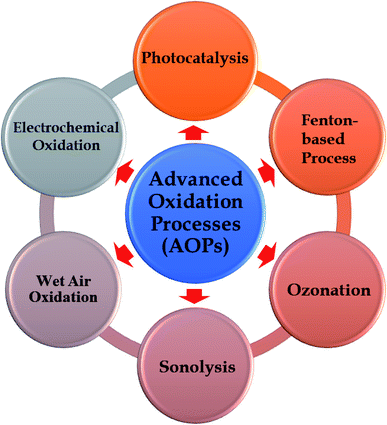
Water pollution has become one of the most serious concerns that Earth will face during the 21st century.1,2 It poses a great threat to human health, the aquatic ecosystem, and economic growth through unknown long-term impacts caused by the presence of emerging pollutants, e.g., personal care products, industrial/household chemicals, pharmaceuticals, and pesticides in water bodies.3,4 In a report carried out by WHO (World Health Organization) in 2015, approximately 1.7 million people lost their lives because of consumption of contaminated water and nearly 4 billion cases of serious health problems caused by water-related diseases annually.5 It was also estimated that half of the world's population will sustain their livings in water-stressed areas by 2025.2,5 Thus, the driving forces for sustainable development must be associated with advanced water treatment techniques. Effective removal of emerging pollutants from wastewater before the eventual discharge into streams is a must to drive water pollution prevention. Traditional methods have been employed to solve this issue, such as biodegradation, ozonation, adsorption/filtration, or coagulation and flocculation.6–10 However, several big challenges hindering the broad application and scale-up of conventional techniques are composed of the formation of toxic by-products, the high operational and maintenance costs, and inefficiency towards complicated compounds.10–12In that context, Advanced Oxidation Processes (AOPs) demonstrated to be a promising and powerful approach in the complete decomposition of harmful pollutants. AOPs are highly efficient techniques in the degradation of emerging pollutants through reaction with hydroxyl radical (˙OH).13,14 Among AOPs methodologies, photocatalysis have recently received an increasing attention (see Fig. 1). Several advantages of photocatalysis can be listed as follows: (i) complete mineralization of recalcitrant pollutants into harmless constituents, (ii) no secondary pollution, (iii) low cost, and (iv) easy operation.15–18 In photocatalysis process, metal oxide semiconductors are the frontliners in photodegradation of organic compounds thanks to their exceptional physicochemical properties.19–23 From the perspective of practical applications, the stability and reusability of photocatalysts is a key factor affecting the scale-up of the whole process. In this regard, the recovery of metal oxide nanoparticles after the reaction is extremely difficult and inefficient, thereby hindering their applications on an industrial scale. More importantly, the presence of metal oxide particles in the final treated effluent possibly causes cytotoxicity and genotoxicity to human beings and aquatic.24–27 In an effort towards overcoming this matter, recent reports proved the feasibility and efficiency towards using the immobilization technique during photoreactions. Despite a few reports on employing glass substrates, graphite, activated carbon, and zeolites28–31 as supporting materials for photocatalysts; however, there is a lack of focused works on the use of waste materials or natural materials. Undoubtedly, using sustainable supporting materials originated from nature (clay and pumice) or industrial wastes (ash and foundry sand) is always worthy of consideration and received intensive interest from the science community.32,33 The utilization of these materials for fixing metal oxides represents an appealing pathway to solve the serious issues faced in the disposal of waste and minimize the costs e.g., costs of the raw materials and disposal waste costs. Unfortunately, the study on the potential application of natural material and waste material as supports for metal oxides is still in the early-stage and rarely reported.
Inspired by this, this work for the first time provides a comprehensive overview of recent advances in the utilization of natural materials (clay mineral and pumice)- and waste materials (ash and foundry sand)-based metal oxide photocatalysts for photodegradation of various pollutants. We also offer potential routes for the progress of green material-based metal oxide photocatalysts and current research gaps to fill for improving photocatalytic performance. The specific objectives of this work are as follows: (1) describe the fundamental principles, mechanism of photocatalysis, and challenges towards using metal oxide as semiconductors; (2) overview of techniques in photocatalyst powder immobilization; (3) introduce the sources, classifications, the properties and chemical composition of green materials, including: ash, clay mineral, foundry sand, and pumice; (4) summarize on recent advances in applications of green materials-based metal oxides composite for the photodegradation of various pollutants.
2. Metal oxides as photocatalysts: fundamental principles, mechanism, and challenges
2.1. Principle and mechanism
In 1911, the “photocatalysis” term for the first time appeared in the scientific literature.34,35 Researchers discovered the light absorption capacity by uranyl ion and catalyst, a material that speeds up the rate of chemical reactions without any changes.36 Since then, several advances achieved had been reported, regarding the employment of metal oxides, such as TiO2 and ZnO, to bleach dyes and Prussian blue.37,38 However, the “photocatalysis” keyword was still not getting noticeable among the scientific community at that time. In the early 1970s, due to the oil crisis and serious environmental deterioration that originated from industrial operations, the demand for seeking alternative energy sources became much more urgent.39,40 During this period, the pioneering works on photocatalysis had been attracted wide attention from the scientific community. In 1968, Boddy et al.41 discovered the evolution of oxygen (O2) on TiO2's surface in an electrolytic cell when irradiating ultraviolet (UV) light. In 1972, Fujishima and Honda42 reported the phenomenon of photoelectrochemical splitting of water (H2O) into O2 on a TiO2 electrode and H2 on a platinum black electrode under UV light. Seven years later, Fujishima's group continued to employ successfully various types of semiconductors for photocatalytic CO2 reduction.43 These pioneering studies truly mark a new era of photocatalysis. Fig. 2 illustrates the progress of historical studies on photocatalysis from the early 1960s to now.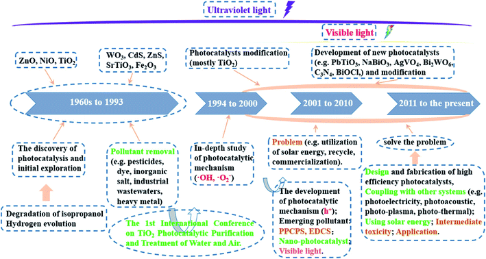 | ||
| Fig. 2 The progress of historical studies on photocatalysis from the early 1960s to present. This figure has been reproduced from ref. 44 with permission from Elsevier, copyright 2020. | ||
Photocatalysis is the combination of photochemistry and catalysis. The “photocatalysis” term composed of two parts “photo” and “catalysis”. Herein, “photo” means light, whereas “catalysis” refers alteration of the chemical transformation rate in the presence of catalyst. Importantly, catalyst neither experiences any changes nor is depleted throughout the process. Thus, photocatalysis is defined as “acceleration of light-induced reaction-derived electron in the existence of catalyst”, in which both factors, light and catalysts, are concurrently utilized to accelerate a chemical reaction. Photocatalytic reaction does not rely on the utilization of any substances (chemicals or gases) that possibly enhance the environmental risks via secondary pollution formation. The whole process primarily depends on light source (photon energy) and the catalyst (or semiconductor) (see Fig. 3).
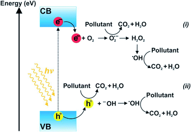 | ||
| Fig. 3 Diagram illustration of photocatalytic reactions (hν ≥ Eg). Oxidation–reduction reactions of electron donors/acceptors occurred in CB (i) and VB (ii). This figure has been reproduced from ref. 45 with permission from Elsevier, copyright 2018. | ||
The mechanism of photocatalytic degradation is illustrated as following steps:46,47
(1) When the surface of a catalyst is illuminated with a proper light source, electrons from the valence band are activated and migrated to the conduction band of the semiconductor, as illustrated in eqn (1). “A proper light source” means its energy must be at least equivalent or higher than the band-gap energy of the semiconductor. In addition, the water molecules would undergo ionization (eqn (2)).
 | (1) |
| H2O → OH− + H+ | (2) |
(2) Positive holes, which were left in the valence band of the semiconductor, react with water molecules to generate hydroxyl radicals (see eqn (3)). Due to the strong oxidizing power, the hydroxyl radicals degrade organic matter molecules into intermediates, or even carbon dioxide and water in some cases (eqn (4)).
| H2O + hVB+ → ˙OH + H+ | (3) |
| ˙OH + pollutant → intermediates + H2O + CO2 | (4) |
(3) Excited electrons in the valence band react with dissolved oxygen species to generate superoxide radicals, as shown in eqn (5). These free radicals will effectively decompose any species adsorbed on the surface of the semiconductor into intermediate products (eqn (6)).
| O2 + eCB− → ˙O2 | (5) |
| ˙O2 + pollutant → intermediates + H2O + CO2 | (6) |
In some cases, superoxide radicals can undergo a series of reactions to produce hydroxyl radicals, as illustrated in eqn. (7).48
 | (7) |
2.2. Semiconductor metal oxides: current challenges
In recent years, metal oxides play an increasingly important role in many fields such as material science, biomedical science, chemistry and physics.49,50 Metal oxides possess the exceptional physicochemical properties which make them ideal materials for critical applications such as removal of heavy metals, photocatalytic degradation of organic contaminants, and biomedical applications.51 In terms of photocatalysis, metal oxides are the frontliners in photodegradation of organic compounds. Several common metal oxide photocatalysts can be listed such as TiO2, ZnO, Fe2O3, SnO, V2O5, Ni2O3. Aside from characteristics like non-toxicity and high chemical stability, the metal oxide-based photocatalysts possess a well-controlled structural with high degree of crystalline, high resistance against photochemical corrosion, and high activity. Recent literature has been demonstrated the promising photocatalytic abilities of metal oxide-based photocatalysts in the degradation of pollutants under UV and visible region.52–55However, of the major interest, the photocatalytic applications are hindered by some limitations of metal oxides-based photocatalysts. For example, TiO2, known as the most widely studied metal oxide nanostructured photocatalyst for decades, possess low quantum yield as the prompt charge recombination of charge carriers, low surface area, and poor sensitivity under solar irradiation. As seen from Fig. 4, the wide bandgap energies of metal oxide such as SnO2 (∼3.5 eV), as similar as TiO2 (3.2 eV) and ZnO (3.37 eV), resulting in they only efficiently work under ultraviolet (UV) light, which makes up for a tiny fraction, with approximately 4% in comparison to the visible light.56
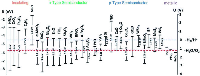 | ||
| Fig. 4 Band-gap energies (eV) and energy levels of conduction band (ECB) and valence band (EVB) of semiconductors. This figure has been reproduced from ref. 57 with permission from Springer, copyright 2018. | ||
Their activities were restricted seriously under visible light, hindering their potential applications for practical usage. Apart from wide band-gap energy, ZnO also owns a low adsorption capacity derived from its non-porous structure, which hinders its photocatalytic performance. Otherwise, several drawbacks of ZnO that can be listed such as unstable in acidic or alkaline medium and low reusable lifespan. Generally, the full-scale applications of metal oxides as photocatalysts are seriously hampered due to the inefficient recovery of most semiconducting photocatalysts after the reaction. Catalysts are in either powder form or particle, and therefore separation process is a must for their recovery from the system. In addition, when using a high content of catalysts for photoreactions, suspended catalysts particles tend to aggregate together and cause light scattering, thereby retarding the photodegradation rate of pollutants.13 To overcome the aforementioned drawbacks, a huge research effort has been devoted to improve the photocatalytic activity of the catalyst via immobilization, doping, co-catalyst interaction, coupling of metal oxides, and sensitization.58–62 Among these strategies, immobilization technique using waste materials (ash and foundry sand) or natural materials (clay minerals and pumice) have been received extensive interest in recent years.63–67 The benefits of this technique are that it can: (i) easily recover and reuse catalysts from the treated effluent stream, (ii) support continuous operation for multiple cycles of photoreactors, and (iii) enhance the photodegradation efficiency of organic compounds from the aqueous solution.13,68 More importantly, the use of natural or waste materials for fixing metal oxides have received increasing attention. This novel approach it is considered an environmental-friendlier approach solving the serious issues faced in the disposal of waste and reducing the costs of the raw materials. From recent literature, several advances achieved till now have studied the huge potential of green materials: ash, clay, foundry sand, and pumice as the immobilized materials. These green materials possess buoyant carriers to accelerate photocatalytic activity by enhancing the exposure of the catalyst particles towards photon energy from light and safely/quickly to be recovered from the water after the treatment process.
3. Overview of immobilization techniques
The immobilization of catalysts on the supporting materials could be carried out by various techniques, consisting of sol–gel, hydrothermal, solvothermal, precipitation, co-precipitation, pyrolysis, hydrolysis precipitation, dip-coating, electrospinning, layer-by-layer assembly, wet chemical synthesis, modified metal–organic decomposition, etc.69–79 The selection of a suitable immobilization technique mainly depends on the type of used photocatalyst, supporting materials, and target pollutants. Herein, several common deposition techniques for metal oxide-based catalysts on ash, foundry sand, clay, and pumice are summarized.3.1. Sol–gel immobilization
Sol–gel immobilization method is the most common technique for the preparation of metal oxide nanoparticles from solution-state precursors. The sol–gel process is an integration of low-temperature and the wet-chemical single process that involves two distinct phases: solution and gelation.80 Fig. 5 shows the diagram illustrating the sol–gel method. Sol is a colloidal suspension of solid particles which was formed during hydrolysis, whereas gel is an integrated 3D network with irreversible metal-oxo-metal bridges which was produced during the condensation step. The last step is drying where the porous network of obtained gel will be destroyed derived from the evaporation of the solvent.81 Both sophisticated equipment and extreme conditions (temperatures or pressure) are not required during the sol–gel process. Instead, this preparation approach possesses several advantages, comprising low-cost, low-temperature operation and high yield.82 The sol–gel method has been widely adopted for preparing ash- and clay minerals-based metal oxide composites.83–88 For example, TiO2 loaded fly ash (FA) catalysts were obtained by adding titanium tetraisopropoxide to acetic acid under continuous stirring for 120 min at 50 °C, and then mixing with an aqueous suspension of the FA before drying process and calcination at 500 °C.89 Similarly, Zn-doped TiO2/C@SiO2 nanoporous with rice husk (RH) as a template was prepared by the addition of Zn–RHA to titania sols and impregnation for 24 h, followed by drying in at 100 °C for another 24 h.90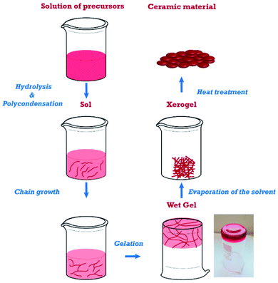 | ||
| Fig. 5 Diagram illustration the sol–gel process. This figure has been reproduced from ref. 82 with permission from MDPI, copyright 2019. | ||
3.2. Hydrothermal and solvothermal
Hydrothermal and solvothermal preparation methods are generally adopted techniques for the fabrication of metal oxides with different morphologies and a higher crystallinity degree without further heat treatment.81 “Solvothermal” term refers to a chemical reaction occurring in a solvent at a temperature that is higher than the boiling temperature of the solvent. In case the water is used as the solvent, then it is called hydrothermal process, while if organic solvents were used, then the whole process is called solvothermal. Additionally, the whole process occurs in a sealed and heated Teflon-line autoclave where nucleation and grain growth reactions occur for crystallinity growth. Teflon-line autoclaves are made up of steel or any other strong alloy and they contain a Teflon liner as an inert chemical substance for the reaction aiming to protects the autoclave from corrosion. Owing to this sturdy structure, Teflon-line autoclaves possess great stability in the high pH medium and become resistant to hydrofluoric acid. Also, they are able to perform reactions under extreme conditions such as high temperature and pressure.86 This method provides precise control over surface morphology, structure, and properties of the synthesized products by adjusting the conditions such as reaction time, temperature, pressure, pH, and solvent type.91 It has been broadly applied for the synthesis of ash- and natural clay minerals-based metal oxide composites.92–94 A recent report by Slewa et al.95 utilized the hydrothermal and solvothermal procedures to successfully synthesize V2O5 nanorods and 3D (micro/nano) V2O5 spheres on macro porous silicon (PSi) substrate (see Fig. 6).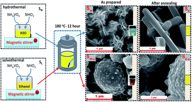 | ||
| Fig. 6 Synthetic routes of the hydrothermal and solvothermal process for fabrication of V2O5 nanorods and 3D (micro/nano) V2O5 spheres. This figure has been reproduced from ref. 95 with permission from Springer, copyright 2019. | ||
3.3. Dip-coating
“Dip-coating” term refers to a popular way of creating a uniform and thin coating of metal oxide nanoparticles onto particularly supporting materials such as pebble beads, clay, or foundry sand.96 First, the natural materials are immersed in a slurry containing coating metal oxides at a constant speed. After a designated time, the supporting materials as substrate with a uniform layer of metal oxide nanoparticles will be pulled out. Later, excess liquid is drained from the substrate, and the solvent starts to evaporate right on the surface of the substrate to form a thin layer.97 The thickness and properties of the coating can be varied, and the influencing parameters can be listed as the number of dipping cycles, deposition time, withdrawal speed, and the viscosity of the solution. Fig. 7 shows the principle of dip-coating method and correlation between the thickness of film and speed of dip coating. Basically, both sophisticated equipment and expensive raw materials are not required during this method, and all steps are also easy to do. Therefore, the dip-coating method is more facile and convenient than the other approaches. However, the major drawbacks of this method have been still remained, consisting of (i) the poor quality and non-uniformity of the coating thickness; and (ii) the high temperature required at the evaporation step, which can negatively affect the mechanical properties of metal oxide composites.97,98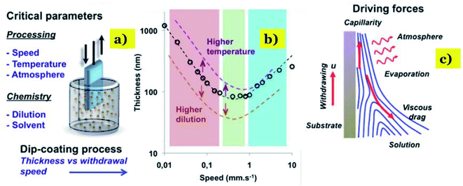 | ||
| Fig. 7 Correlation between the thickness of film and speed of dip coating: (a)-dip-coating method and critical parameters; (b) correlation between the speed of coating and film thickness versus the dilution and temperature. (c) Correlation between the thickness of film and evaporation rate. This figure has been reproduced from ref. 99 with permission from RSC, copyright 2011. | ||
3.4. Coprecipitation
Coprecipitation is a novel technique for the precipitation of metal in the form of hydroxide from a salt precursor with the presence of amounts of the base in a solvent.49 Accordingly, the first stage is the precipitation of inorganic salts caused by the introduction of base or acids, followed by the irreversible conversion into final products, metal oxide nanoparticles, resulted from the calcination of the precursors.81 The growth kinetics of nucleation and particle depends on the generated anions and cations, which is the driving force of monodispersed nanoparticle formation. Even though this method is able to produce particles with the size range from submicron to tens of microns; however, the monitor of particle size and chemical homogeneity remains a challenge in the precipitation of mixed oxide. In addition, some disadvantages of this approach can be pointed out as follows: (i) time-consuming process, (ii) the precipitation of trace impurities during the first stage, (iii) negative effects of reactants possessing distinct precipitation rates, and (iv) reproducibility issues.100 Typically, Ashik et al.101 successfully fabricated NiO, FeO, and CoO nanoparticles with silicate incorporation (Stöber method) via coprecipitation by treating the respective metal nitrate solution with ammonia (Fig. 8). Herein, TEOS and C18TMS were also used to develop silicate support to guard the active metal phase. Similarly, n-NiO/SiO2 nanoparticles was fabricated through coprecipitation from the respective nitrate precursor (Ni(NO3)2·6H2O).102 In this study, Ni(NO3)2·6H2O precursor was converted to Ni(OH)2 under the precipitation form by dropwise addition of ammonia solution (30% NH3) under sonication for 1 h. The nanosized Ni(OH)2 was collected by centrifugation and washed twice with distilled water and ethanol. The formation of silicate support was achieved through the hydrolysis of tetraethylorthosilicate (TEOS) and octadecyl trimethoxy silane (C18TMS) with ammonia solution in the suspension of nanometal hydroxide under sonication for 1 h. Finally, n-Ni(OH)2/SiO2 precipitate was dried at 100 °C for 15 h and then calcined at 450 °C for 3 h to form n-NiO/SiO2 nanocatalysts.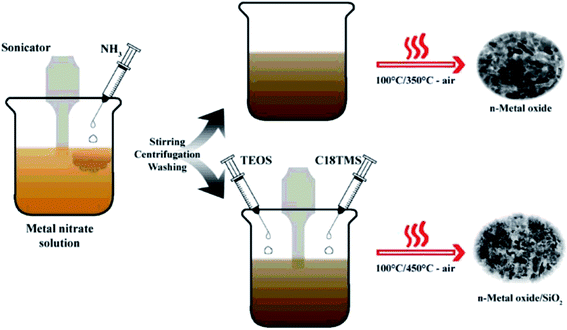 | ||
| Fig. 8 Synthetic pathway of the coprecipitation process to fabricate nano-metal oxides (NiO, FeO and CoO) and nano-metal oxide/silicates. This figure has been reproduced from ref. 101 with permission from Elsevier, copyright 2015. | ||
3.5. Spray pyrolysis
Spray pyrolysis is a low-cost coating technique that involve a precursor solution and a heated support material and atomizer.103 In this process, the precursor solution undergoes atomization in fine drops and these droplets are migrated to the surface of heated support material due to gas. After evaporation, the precipitate continues to undergo thermolysis at a high temperature, followed by the formation of the desired solid particles and thin films.104 The mechanism of spray pyrolysis is illustrated in Fig. 9. This technique owns several advantages, consisting of low cost, the simplicity of apparatus, high efficiency, and produced thin films possessing a large surface area of substrate coverage. However, the poor quality of thin films remains an obstacle towards the application potential of this method. Furthermore, their controlled thermal decomposition and the preparation of fine and uniform droplets of reactants are big challenges.105 This technique is applied in the preparation of natural material-based metal oxide composite. For example, a report by Zhang et al.106 described the modified pyrolysis process (the calcination temperature at 450 °C for 1 h) to synthesize the catalyst of fly ash cenospheres (FACs)-supported CeO2 (CeO2/FACs). By applying the same technique, a cow bone char (BC) ash decorated with MgO–FeNO3 was successfully fabricated through the calcination at 500 °C for 2 h.75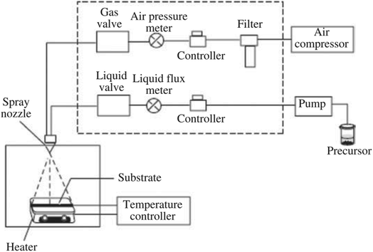 | ||
| Fig. 9 Diagram illustration of the pyrolysis process's mechanism. This figure has been reproduced from ref. 103 with permission from Elsevier, copyright 2020. | ||
3.6. Electrospinning
Electrospinning or “electrostatic spinning” is a voltage-driven advanced technique for producing ultrathin fibers with diameters in the range of ten nanometers to micrometers.107 In the production of nanofibers, by applying a specific voltage from a high voltage power source, the polymer drop of an electrospinning solution becomes charged. Electrostatic repulsion starts to resist the surface tension of the liquid. As a results, the polymer drop is stretched at a critical point of liquid stream eruption and completely converted into a fine liquid jet.108 Compared to other methods, the main advantage of electrospinning is its versatility and easy production to produce fibers with multiple morphological structures from a wide variety of materials.109 Fig. 10 illustrates the development of electrospinning process. In 2015, the electrospinning process was used by Saud et al.110 to fabricate the FA/TiO2 composite nanofibers. First, a certain amount of titanium tetraisopropoxide was dissolved in acetic acid, followed by the addition of PVP, ethyl alcohol, and FA into the solution under magnetic stirring for 6 h. Subsequently, the obtained mixture was electrospun at 15 kV, and then dried at 60 °C for 12 h before calcination at 600 °C for 3 h. Aside from TiO2, fly ash incorporated ZnO nanofibers were also successfully synthesized via the same technique.77 First, the mixture of fly ash and zinc acetate solution underwent a sonication for 1 h, and then the solution was mixed with the poly(vinyl alcohol) solution. Subsequently, the obtained mixture was electrospun at the applied voltage of 20 kV, followed by drying 30 °C for 6 h before calcination at 550 °C for 2 h to finally achieve the FA/ZnO nanofibers.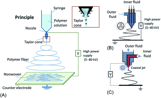 | ||
| Fig. 10 Diagram illustration of the development of electrospinning technique: (A) principles; (B) three channel; and (C) one channel as inner fluids. This figure has been reproduced from ref. 111 with permission from Elsevier, copyright 2019. | ||
In short, amongst the aforementioned immobilization methods, sol–gel immobilization is considered the most common and simple technique in preparing metal oxide-based photocatalysts due to its simplicity which does not require any either sophisticated equipment or extreme conditions (temperatures or pressure). Furthermore, the tunable surface morphology of the metal oxide nanoparticles fabricated by this method is also a plus point. Comparatively, hydrothermal and solvothermal possess advantages, consisting of a one-step synthesis process and precise control over the physicochemical properties of the synthesized products. However, this technique requires high operating temperatures and therefore the morphology of the product could be easily influenced. Also, the need for consumed energy and expensive Teflon autoclave poses safety precautions as well as additional costs. The dip-coating method is more facile and convenient than hydrothermal and solvothermal. However, the poor quality and non-uniformity of the coating thickness and effects of the high temperature at the evaporation step on the mechanical properties of metal oxide are the major drawbacks of this approach. Similarly, spray pyrolysis is able to produce thin films possessing a large surface area of substrate coverage; however, the poor quality of thin films remains an obstacle to the application potential of this method. Coprecipitation is able to produce particles with the size range from submicron to tens of microns; however, the monitor of particle size and chemical homogeneity remains a challenge. Last, compared to other techniques, the advantage of electrospinning is its versatility and facile production to synthesize fibers with multiple morphological structures from various materials.
4. Green materials-based metal oxides nanocomposites: properties, mechanism and performance
This section highlights the potential applications of natural material (clay mineral and pumice) and waste material (ash and foundry sand) as “green” materials for fixing metal oxide-based in photocatalytic degradation of various contaminants. Applications of “green” materials supported photocatalysts for contaminants degradation with reaction conditions are summarized in Table 1.| Photocatalyst | Pollutant | Degradation efficiency (%) | Operating conditions | Ref. | |||
|---|---|---|---|---|---|---|---|
| Pollutant concentration (ppm) | Catalyst dosage (mg) | Reaction time (min) | Light source | ||||
| a VA: volcanic ashes, FA: fly ash, FACs: fly ash cenospheres, RHA: rice husk ash, FS: foundry sand, FE: fuller's earth, PDMS: polydimethylsiloxane. | |||||||
| TiO2 supported VA | Methylene blue | 100 | 20 | 2400 | 30 | UV | 93 |
| Fe2O3–TiO2/FACs | Methylene blue | 86.81 | 2 | 100 | 60 | Visible | 112 |
| ZnO/FA | Methylene blue | 100 | 10 | 15 | 180 | UV | 113 |
| Fe/TiO2–FACs | Methyl blue | 50 | 20 | 1800 | — | Visible | 84 |
| Zn/TiO2–RHA | Rhodamine B | 95 | 0.47 | 25 | 100 | Visible | 90 |
| TiO2–FA | Reactive red 45 | 90 | 30 | 100 | 90 | UV | 114 |
| TiO2 pillared montmorillonite | Methylene blue | 98 | 30 | 50 | 90 | UV | 115 |
| Cu(II)-grafted TiO2–imogolite | Acetaldehyde | 100 | 200 | 50 | 1500 | Visible | 116 |
| Halloysite:palygorskite–TiO2 | NOx gas | 98 | 1 | 40 | — | UV | 117 |
| ZnO/clay | 2-Chlorophenol | 88 | 20 | 200 | 60 | Solar light | 118 |
| ZnO/kaolinite | 2-Chlorophenol | 100 | 20 | 200 | 60 | Solar light | 119 |
| TiO2/kaolinite | Acid red G | ∼98 | 50 | 150 | 60 | UV | 120 |
| TiO2/kaolinite | 4-Nitrophenol | 90 | 10 | 100 | 240 | UV | 120 |
| Fe–TiO2/FA–FS | Pentoxifylline | 88 | 50 | — | 120 | Solar light | 121 |
| TiO2/FE–FS | Metronidazole | 85 | 25 | — | 45 | Solar light | 122 |
| FS/FA/TiO2 | Cephalexin | 89 | 50 | — | 240 | UV | 123 |
| FS/FA/TiO2 | Cephalexin | 94 | 50 | — | 210 | Solar light | 123 |
| N–Ag–TiO2/FS–FA | Cephalexin | 77 | 50 | — | 60 | Solar light | 124 |
| TiO2/FS | Phenazone | 96 | 50 | — | 240 | Solar light | 125 |
| TiO2–pumice | Methylene blue | 100 | 0.355 | 1600 | 2880 | UV | 126 |
| Fe3O4/ZnO@pumice | Methylene blue | 85.5 | 10 | 50 | 60 | LED light | 127 |
| ZnO/pumice | Dye | 90.17 | 3.01 | 600 | 45.04 | Solar light | 128 |
| PDMS–SiO2–TiO2–pumice | Methylene blue | 59 | 5 | — | 1800 | Visible | 129 |
4.1. Ash-based metal oxides
In the field of environmental remediation, ash is recently utilized as the efficient support material in advanced photocatalysis systems. Owing to superior properties comprising spherical particles with a unique porosity structure, lightweight property, safety, and high strength make ash green materials for critical applications in environmental remediation.130,131 From recent literature, several common types of ash used as natural photocatalysis supports consist of fly ash, rice husk ash, and volcanic ash. Fly ash (FA) is a solid particulate material produced from the combustion of coal and biomass that has a negative effect on the environment and human beings. It is reported that thousands of hectares of land will be required for the disposal of generated FA.132 When it comes to fly ash-based photocatalysts, coal fly ash released from the burning of pulverized coal in coal-based thermal power plants (at 1200–1700 °C) is the most popular type used as the natural adsorptive precursor.133 Coal fly ash is a heterogeneous material containing components of silica, calcium oxide, alumina, ferrous oxide, and carbon. The ratio of these components mainly depends on the mineralogical composition of used coal precursors and the parameters of the combustion process.134 Volcanic ash (VA) is a mixture of fine rock and mineral particles expelled from an explosive volcanic eruption.135 Rice husk ash (RHA) is an agricultural waste produced from the complete burning of rice hulls. It is estimated that rice production in developing countries annually creates roughly 100 million tons of rice husk as low-value agricultural by-product.136 RHA mainly contains SiO2 (80–90 wt%) in the crystalline form, carbon (10–20 wt%), and negligible amounts of metallic elements.137In 2010, Esparza et al.93 presented nanostructured TiO2 supported over volcanic ashes (TVA) obtained by a hydrothermal method. Synthesized TVA displayed excellent photocatalyst behavior in the decomposition of MB with a high removal efficiency of 100% after 60 min. Additionally, this powder composite exhibited great reusability and stability after eight consecutive cycles of photodegradation of MB. Saud et al.110 successfully prepared FA incorporated TiO2 nanofibers via electrospinning technique followed by calcination at 600 °C for 3 h in air. During calcination, both the evaporation process of solvent and decomposition of polymer took place, resulting in a decrease in the diameter of fibers. FA particles are embedded homogeneously on the surface of TiO2 nanofiber. A necklace-like structure was observed in the sample of FA/TiO2, which showed how FA particles distributed throughout the nanofibers during the process of calcination (see Fig. 11a). The PL results pointed out that the addition of FA into the TiO2 structure effectively hindered the recombination of charge carriers. Undoubtedly, this is a plus point in the case of using the materials as efficient catalysts in the photoreactions. The incorporation of FA promotes the antibacterial capacity of bare TiO2 under mild UV radiation through the generation of active oxygen radicals, which are capable of reacting with cell membranes, DNA, and cellular proteins, resulting in cell death (Fig. 11b). This can be explained by the formation of the electrostatic interaction between the negative zeta potential of TiO2 and the metal ions of FA which inhibited sudden discharge from TiO2 fibers.138 In another approach, Zhu et al.112 utilize coal flying ash cenosphere (FAC), collected from the Huainan fossil-fuel power station, to improve catalytic activity and photostability of TiO2 and Fe2O3 under visible range. Accordingly, TiO2 film with Fe2O3 doped onto FAC was loaded via sol–gel technique, and the photocatalytic performance of Fe2O3–TiO2/FAC was evaluated via the photodegradation of methylene blue under visible light irradiation. The morphological features of FAC, TiO2/FAC, and the composite of Fe2O3–TiO2/FAC appear in Fig. 11c–f. SEM photos clearly illustrated spherical particles with a diameter in the range of 100–150 μm, and this implies that the structure of FAC underwent insignificant change throughout the modified process. The loading of Fe2O3 and TiO2 particles makes the bare FAC's surface to be unsmooth and rougher (see Fig. 11e). The UV-vis DRS spectrum of Fe2O3–TiO2/FAC shifts from the ultraviolet to the visible region, 650–700 nm, implying the absorption intensity of the composite improved in the visible region. In addition, the BET surface area of Fe2O3–TiO2/FAC (4.4806 m2 g−1) was much higher than that of pure FAC (0.3815 m2 g−1). These improvements show a superior visible light-harvesting capacity of Fe2O3–TiO2/FAC composite. As a result, the Fe2O3–TiO2/FAC composites showed more efficient photocatalytic performance than TiO2/FAC and Fe2O3/FAC. Interestingly, the author assumed that a 3d electron of an Fe3+ center may migrate to the conduction band of TiO2/FAC, followed by an oxidation reaction to convert Fe3+ into Fe4+. Then, Fe4+ reacts with OH− to generate hydroxyl radicals, whilst the free electrons reduce O2 to release superoxide anion radicals (see Fig. 11g).
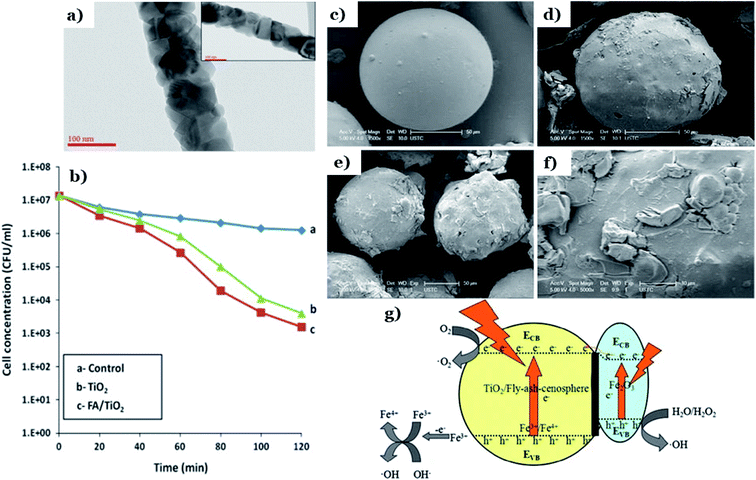 | ||
| Fig. 11 TEM photos of FA/TiO2 composite and inset showing the necklace-like structure (a); antibacterial efficiency of various catalysts on E. coli bacteria under UV radiation (b). This figure has been reproduced (adapted) from ref. 110 with permission from Elsevier, copyright 2014. The SEM photos of FAC (c), TiO2/FAC (d), Fe2O3–TiO2/FAC (e), the local enlargement of Fe2O3–TiO2/FAC (f); mechanism of visible-light-driven photodegradation using Fe2O3–TiO2/FAC (g). This figure has been reproduced from ref. 112 with permission from Springer, copyright 2015. | ||
Aside from TiO2 and Fe2O3, ash also utilized as support material to improve the catalytic activity of other metal oxides such as ZnO or Ni2O3. Shaban et al.70 used agricultural rice husk derived from a local rice-producing factory in Egypt to prepare MCM-48 mesoporous silica loaded by Ni2O3 (MCM-48/Ni2O3) via a conventional hydrothermal process. Effect of heating from calcination at 550 °C for 8 h results in the formation of a porous structure with the non-spherical and irregular particles in as-synthesized MCM-48 sample. The nickel oxide crystalline grains (2 mm to 5 mm) under euhedral forms distributed homogeneously on the surface of MCM-48 (Fig. 12a and b). The addition of MCM-48 derived from RHA promotes the textural properties and reusability of pure Ni2O3 (see Fig. 12c). The BET surface area of MCM-48/Ni2O3 (1126 m2 g−1) was much improved compared to bare Ni2O3 (76.4 m2 g−1), which provides more active sites for adsorption and photoreactions. Interestingly, the authors carried out a test with Congo red dye as a model pollutant to determine the role of MCM-48 toward improving the adsorption and photocatalytic activity of Ni2O3. After 120 min, the degradation efficiency using Ni2O3 achieves only 15.4%, whereas MCM48/Ni2O3 reaches an elimination percentage of up to 45%. In another research, Kim et al.113 fabricate clustered ZnO-doped fly ash particle composite material (ZnO/FAPs) via a hydrothermal process. The FAPs are irregular, spherical, and porous fine particles with diameters ranging from 0.1 to 100 μm. ZnO consists of flower-shaped particles (Fig. 12d). The unique morphological features of ZnO/FAP composites showed irregular clusters of ZnO flowers distributed homogeneously on the surfaces of FAPs (Fig. 12e). FAPs played an irreplaceable role in the growth of ZnO particles through strong interactions between ZnO and FAPs, leading to an increase in the total surface area of ZnO/FAP composites (from 6.08 to 30.89 m2 g−1). Compared to pure ZnO with a removal percentage for MB of 5% after 180 min, the photodegradation efficiency of ZnO/FAP composites was remarkably improved being up to 100% after only 2 h (see Fig. 12f).
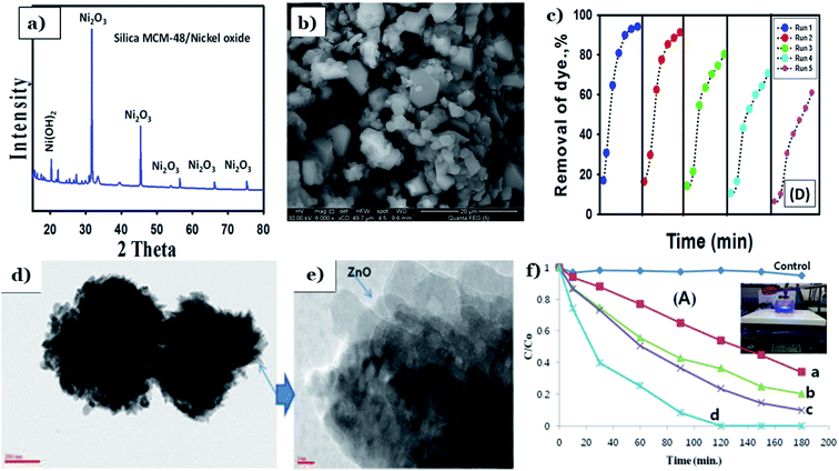 | ||
| Fig. 12 XRD pattern (a) and SEM image (b) of synthesized MCM-48/nickel oxide; reusability of the catalyst (c). This figure has been reproduced (adapted) from ref. 70 with permission from Elsevier, copyright 2017. TEM images of pristine ZnO flowers on the surface of FAPs (d and e); The MB photodegradation over different catalysts (f). This figure has been reproduced from ref. 113 with permission from National Institute R and D of Materials Physics, copyright 2014. | ||
4.2. Clay-based metal oxides
Natural clay minerals are potential support materials since they exhibit excellent physicochemical properties such as large BET surfaces areas, large pore volumes, high chemical and mechanical stability and they are abundant in nature.139 Clay minerals are a diverse group of aluminosilicate layers, mainly comprising 1:1-type which means each layer contains one tetrahedral silica sheet and one octahedral alumina sheet (e.g., halloysite and kaolinite) and 2:1-type that implies one layer consists of one octahedral sheet located between two tetrahedral sheets (e.g., vermiculite, sepiolite, and montmorillonite).140 Recent decades, 1:1 clay mineral-based nanocomposites have been widely studied in environmental applications due to their good physicochemical properties.141 Among that, halloysite, a typical candidate of 1:1 type, possess a unique nanotubular structure with excellent characteristics such as high mechanical, thermal and chemical stability, high reusability, and high surface/volume ratio, strong adsorption capacity (see Fig. 13a).142 Therefore, halloysite is considered a potential low-cost alternative to synthetic expensive and commercial carbon nanotubes. Halloysite can act as a stabilizer to inhibit agglomeration of metal oxide nanoparticles as their unique tube structure and large specific surface area. In the 2:1-type clay minerals, the layers are connected by hydrogen and electrostatic bonding forces. Furthermore, the excessive negative charge on the surface may interact with charge-balancing cations (e.g., cations located in the interlayer space) via electrostatic forces (see Fig. 13b).143 Thus, 2:1-type clay minerals possess superior properties such as a large surface area, high adsorption capacity, and good ion-exchange capacity, which make them potential candidates for applications in adsorption and catalytic fields.144 Dispersing metal oxide nanoparticles onto the surfaces of clay minerals is proved to efficiently enhance the photocatalytic activity of metal oxide catalysts by generating more active surface sites and reducing the agglomeration of particles, thereby remarkably improving light-harvesting capacity.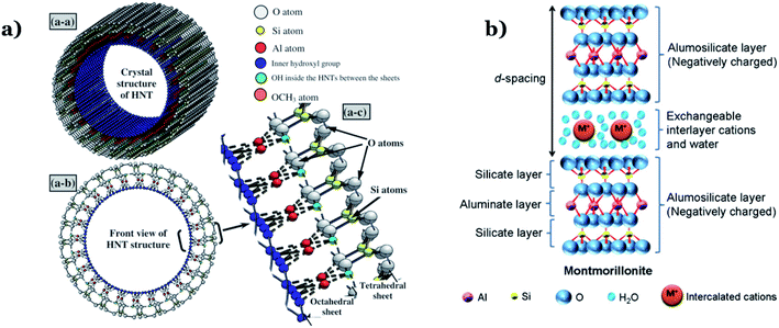 | ||
| Fig. 13 Diagram illustration of the layer structure of: (a) halloysite nanotube. This figure has been reproduced from ref. 145 with permission from Elsevier, copyright 2013; and (b) montmorillonite clay. This figure has been reproduced from ref. 146 with permission from Elsevier, copyright 2012. | ||
Chen et al.115 obtained the delaminated TiO2 pillared clays from montmorillonite (Mt) clay and sol of titanium hydrate in the presence of POP (polymeric surfactant poly(oxypropylene)-amines) (see Fig. 14a). Clay mineral particles can isolate and prevent the nanocrystalline anatase particles from agglomerating together and further transforming into rutile. There is no anatase-to-rutile phase transformation obtained in XRD patterns of TiP–Mt samples under a temperature range of 0–900 °C (Fig. 14b). POP can act as an expanding agent and the fragments of clays and TiO2 nanoparticles were distributed homogeneously on the POP template via TEM image (Fig. 14c). This demonstrates that POP promotes the formation of the delaminated structure of Mt and enhances the porosity and surface area of the composites. The specific surface area was the key factor leading to the expansion of the contact area between the nanocomposite particles and the dye. This is the main driving force behind the enhanced photocatalytic performance of as-synthesized composites (up to 98% MB degradation within 90 min). Katsumata et al.116 successfully fabricated Cu(II)-grafted TiO2–imogolite composite. Imogolite, a typical candidate belonging to aluminosilicate minerals, comprises a layer of octahedral (aluminum hydroxide) on which isolated silicate groups are bound upright to the octahedral vacancy through covalent bonding between oxygen atoms (Fig. 14d).147 Owing to a unique nanotubular structure, imogolite possesses a large specific surface area which makes it an ideal absorbent for applications in the environment. A grain-like morphology with polygonal grain shapes was found in TiO2–imogolite composites (Fig. 14e). Their morphology was nanotubular with 3–5 nm outer diameter, and the specific surface area was 245 m2 g−1. The addition of imogolite results in a strong surface affinity for water molecules. In addition, photodegradation of acetaldehyde under UV and visible light using TiO2–imogolite composites was much higher than that of pure TiO2, and this implies an irreplaceable role of imogolite towards efficiently adsorbing the acetaldehyde. Interestingly, the authors found that imogolite adsorbs not only acetaldehyde but also the intermediates such as CH3COOH during the decomposition of acetaldehyde and these products are then degraded to CO2 by the radical species released on the catalyst surface (Fig. 14f).
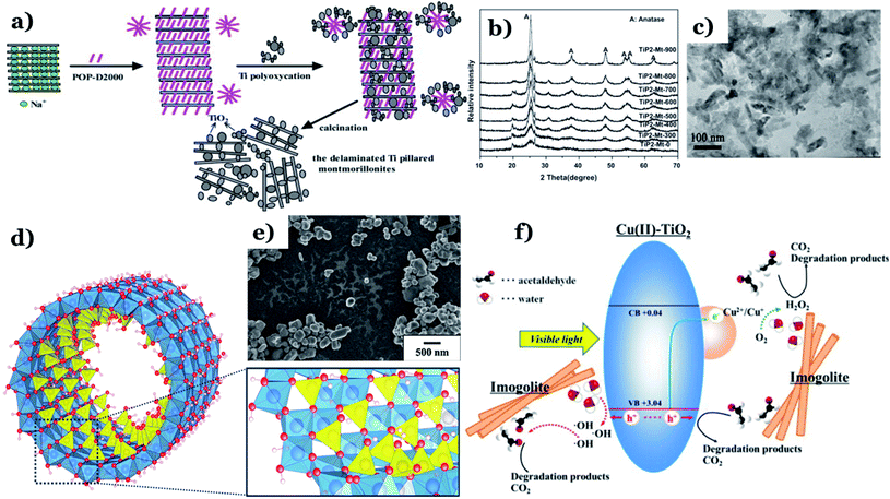 | ||
| Fig. 14 Synthetic pathway of the TiO2 pillared montmorillonites (a); XRD patterns of TiP2–Mt samples with different calcination temperatures (b); TEM images of TiP2–Mt-500 (c). This figure has been reproduced (adapted) from ref. 115 with permission from Elsevier, copyright 2012. Structure of a single-walled imogolite nanotube. Note: red-oxygen, white-hydrogen, blue-aluminum, and yellow-silicon (d). This figure has been reproduced from ref. 147 with permission from MDPI, copyright 2018; SEM images of the TiO2–imogolite composite (TiO2 0.5–imo sample) (e); proposed mechanisms of acetaldehyde removal under visible light irradiation using Cu(II) grafted TiO2–imogolite composite (f). This figure has been reproduced (adapted) from ref. 116 with permission from Elsevier, copyright 2013. | ||
Using 1:1 type clay mineral, for example halloysite, with tubular morphology was favorable to the dispersibility and photocatalytic performance of metal oxides nanoparticles. Papoulis et al.117 obtained for the first-time nanophase TiO2 particles supported on a combination of two different nanoclay minerals: palygorskite (fibrous morphology) and halloysite (tubular morphology) via hydrothermal treatment at 180 °C. The authors found that synthesize of two nanoclays led to significantly reduced agglomeration of the clay mineral particles, which results in an expansion of more sites on their surfaces for the metal oxides deposition (see Fig. 15a). TiO2 particles are distributed homogenously on the external surfaces of palygorskite fibres and halloysite tubes, and their grain size ranged from 3–10 nm (Fig. 15b). Importantly, the three phase nanocomposites (two nanoclays) (Hal:Pal–TiO2) exhibited a higher photocatalytic performance toward decomposition of NOx gas and toluene vapor, as compared to that of single nanoclay–TiO2 (palygorskite– or halloysite–TiO2) under UV and visible region. Recently, Zyoud et al.119 utilized kaolinite as an efficient supporting material for ZnO (ZnO/KAOL) in the decomposition of 2-chlorophenol under solar light. Kaolinite is a non-expandable solid material and classified as 1:1 type layer silicates (Fig. 15c). It possesses a rigid structure, high chemical stability, small BET surface areas, low expansion, and cation exchange capacity. The SEM image illustrates agglomerations of ZnO crystallite nanoparticles (∼200 nm) on the kaolinite flakes (∼8 μm). The addition of kaolin promotes the photocatalytic activity of ZnO in the decomposition of 2-chlorophenol at various mediums. The HPLC results indicates the complete mineralization of reacted 2-chlorophenol molecules during 180 min. Notably, kaolinite plays an irreplaceable in enhancing reusability of ZnO nanopowder catalyst. ZnO/KAOL can easily be recovered by simple decantation or filtration, and especially this composite exhibited excellent stability after five consecutive cycles of photodegradation of 2-chlorophenol (Fig. 15d).
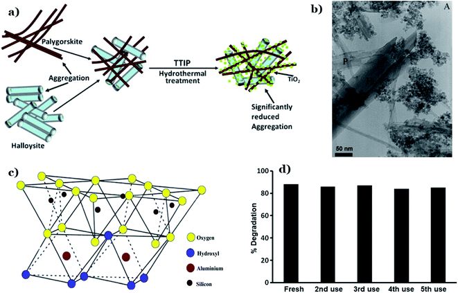 | ||
| Fig. 15 Diagram illustrations of three-phase nanocomposites with two nanoclays via hydrothermal technique (a); TEM image of Hal20:Pal10–TiO (b). This figure has been reproduced (adapted) from ref. 117 with permission from Elsevier, copyright 2013. Structure of kaolinite (c). This figure has been reproduced from ref. 148 with permission from Springer, copyright 2020. Stability of the ZnO/KAOL composite on reuse for five times (d). This figure has been reproduced from ref. 119 with permission from Springer, copyright 2019. | ||
4.3. Foundry sand-based metal oxides
Foundry sands (FS) are by-products originated from the ferrous and nonferrous metal casting industry, in which sand is utilized as a molding material.149 During the casting process, used sand particles gradually break down over time due to mechanical abrasion and heat, and consequently, these sand grains will be discarded from the system (known as FS). Instead, new sand grains will be continuously added to the process to inhibit casting defects.150 The physicochemical properties of FS mainly rely on the type of metal being cast, the type of used furnace (e.g., electric arc, induction, and cupola), the process parameters, and the selected finishing process (e.g., blast cleaning, grinding, and coating). Based on the type of binder selected for casting, FS can be classified into green sands and chemically bonded sands. For casting purposes, green foundry sands are preferable, and they mostly consist of 85–95% of silica sand, 4–10% of the bentonite clay as a binder and, 2–10% of carbon materials. Chemically bonded sands are preferably utilized in mold making since this step requires high thermal resistance of the molten metal. Chemically bonded sands are composed of 93–99% silica and 1–3% chemical binder (e.g., epoxy-resins, phenolic-urethanes, sodium silicates, or furfuryl alcohol).151,152 Chemically bonded sands are generally lighter in color and in texture than green sands (Fig. 16). It is estimated that millions of tons of waste FS are generated annually, posing a tremendous environmental challenge.153,154 Traditional solutions such as disposal of foundry sand in landfills usually require high costs and land resources.154 Therefore, how to use sustainably FS as an economical and green solution remains a challenge till now. Inspired from this, this section briefly summarizes the potential of using FS as supports for the preparation of photocatalysts for the degradation of various pollutants.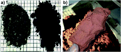 | ||
| Fig. 16 (a) Green sands and (b) chemically bonded sands. This figure has been reproduced from ref. 152 with permission from Elsevier, copyright 2020. | ||
As early as 2020, Talwar et al.122 designed the fixed-bed in situ continuous three reactors approaching plug flow (PFR) for the decomposition of metronidazole (MTZ) under solar irradiation. PFR has utilized the composite beads composed of fuller's earth and FS. Interestingly, both components contain a certain amount of iron, which makes them ideal materials for the in situ dual effect of both photocatalysis and photo-Fenton (see Fig. 17a). The dual effect leads to a significant decrease in the treatment time of MTZ which lasts only 45 min with a removal percentage of 84% using PFR at a flow rate of 8 L h−1, while individual processes (photo-photocatalysis and Fenton) took up to 3.5 h for only 45% removal. Stability and reusability after multiple times of the catalysts in the powder form remain a huge challenge for many practical applications. The addition of waste materials such as FS as supports into TiO2 nanoparticles brings excellent reusability, which was proved through 80 repeated continuous cycles (see Fig. 17b). FS brings significant binding strength to the composite. More importantly, no changes were observed in the structure of catalyst after 80 cycles, and this implies the basic structure of TiO2 was maintained after each use (Fig. 17c). Additionally, the calculated band-gap energies for the initial and recycled composites were 2.8 eV and 2.77 eV, respectively, in comparison to P25–TiO2, being 3.2 eV. This illustrates a visible light-harvesting efficient capacity of the as-synthesized composite. In a report in 2017, Bansal et al. utilized waste FS and FA as a support material and alternative iron source along with TiO2 for degradation of pentoxifylline (PEN) under solar light.121 The addition of FS and FA encompass properties of the in situ dual effect of both photocatalysis and photo-Fenton (Fig. 17e). Fig. 17d shows actual photos of TiO2 immobilized clay beads containing FS and FA. The authors concluded that the addition of FS and FA results in superior photocatalytic activity with reduced treatment time (e.g., three times reduction in slurry mode) along with excellent reusability of the composite after 45 recycles without any changes in the structure of TiO2. In the same year, Bansal et al.123 also successfully fabricated spherical bead-like support materials from three natural raw materials: FS, FA, and clay to fix TiO2 (FS/FA/TiO2 beads). The presence of FS and FA leads to an in situ iron generation and then dual effect (photo-Fenton and photocatalysis) in the same system, thus promoting to synergistic effect for the decomposition of antibiotic cephalexin. At optimized conditions, the hybrid of FS/FA/TiO2 beads exhibited the highest cephalexin removal percentage (89%) among various catalysts and a corresponding reduction in COD of 82%. Besides, owing to significant binding strength between components, FS/FA/TiO2 beads illustrated great stability after 35 repeated recycles without any changes in the structure of TiO2. One year later, Bansal and Verma124 continued to prepare F–N–Ag–TiO2 composite beads, in which waste FS and FA act as support material and also an alternative source of iron. The in situ dual process using F–N–Ag–TiO2 composite beads exhibited a removal percentage towards cephalexin up to 77% after 1 h under sunlight with an overall synergy of 24% over individual processes. Recently, the same group pointed out two key roles of FS, consisting of (i) natural supports material for TiO2 during photocatalysis reaction and (ii) a supplement for iron in case of photo-Fenton reaction.125 TiO2 particles are immobilized on a hollow circular composite disc and this unique combination exhibited a removal percentage of phenazone up to 96% after 4 h under solar irradiation. The hollow circular composite disc was synthesized by utilizing FS and clay in the ratio (1![[thin space (1/6-em)]](https://www.rsc.org/images/entities/char_2009.gif) :
:![[thin space (1/6-em)]](https://www.rsc.org/images/entities/char_2009.gif) 1). Clay acts as a binding material, while FS was employed as an iron source. This unique combination brings significant binding strength to the composite disc. As a result, TiO2 immobilized composite disc possesses great stability even after repeated 10 cycles with roughly 20% depletion in the degradation efficiency.
1). Clay acts as a binding material, while FS was employed as an iron source. This unique combination brings significant binding strength to the composite disc. As a result, TiO2 immobilized composite disc possesses great stability even after repeated 10 cycles with roughly 20% depletion in the degradation efficiency.
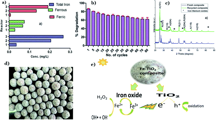 | ||
| Fig. 17 Contents of total iron, ferrous, and ferric ions leached out from the beads with the passage of every reactor throughout the photodegradation of MTZ (a); catalytic stability of composite beads for MTZ degradation (b); XRD patterns of fresh and recycled composite (c). This figure has been reproduced (adapted) from ref. 122 with permission from Elsevier, copyright 2019. Actual photograph of Fe–TiO2 immobilized composite (FS and FA) beads (d); diagram illustrations of possible synergistic effect in dual-process under solar irradiation (e). This figure has been reproduced (adapted) from ref. 121 with permission from Elsevier, copyright 2017. | ||
4.4. Pumice-based metal oxides
Pumice refers to a type of extrusive volcanic rock originated from volcanic eruptions. During eruption, lava containing a high content of water and gases is continuously released from volcanic, followed by the prompt evaporation of gases. Consequently, the lava rapidly cools and becomes frothy, resulting in the formation of a light and soft rock material with a porous structure filled with small gas bubbles.155,156 In fact, pumice could be easily found everywhere in or nearby volcanic mountains. Highly porosity (∼90%) and amorphous nature of natural pumice form its high specific surface area and skeleton structure consisting of many empty pores that can acts as channels to transport substances like of water and ions.157 The porous and very rough surface of pumice can be easily observed through TEM images (see Fig. 18a–c). Basically, pumice mainly consists of SiO2; however, the ratio of components of each specific pumice varies and depends on different locations around the world.158 Table 2 illustrates chemical compositions of pumice originated from different locations around the world.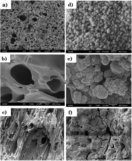 | ||
| Fig. 18 SEM images of pure pumice (a and b); SEM images of TiO2-mounted pumice (d and e). This figure has been reproduced (adapted) from ref. 126 with permission from Elsevier, copyright 2004. Micrographs of a pellet of: bare pumice (c), and pumice stone impregnated with TiO2–P25 (f). This figure has been reproduced (adapted) from ref. 65 with permission from Elsevier, copyright 2003. | ||
| Composition | Lipari, Sicily, Italy159 | Tikmeh Dash Reign, East Azerbaijan, Iran160 | Nevşehir, Turkey161 | Kayseri, Turkey161 | Isparta, Turkey161 | Balıkesir, Marmara, Turkey162 | Tenerife Island, Spain163 |
|---|---|---|---|---|---|---|---|
| SiO2 | 71.75 | 63.45 | 74.1 | 68.5 | 59.0 | 52.70 | 52.5 |
| Al2O3 | 12.33 | 17.24 | 13.5 | 14.9 | 16.6 | 3.80 | 19.7 |
| Fe2O3 | 1.98 | 2.86 | 1.4 | 3.1 | 4.8 | 0.07 | 3.7 |
| FeO | 0.02 | — | — | — | — | — | — |
| TiO2 | 0.11 | 0.37 | 0.07 | 0.2 | 0.6 | — | — |
| MgO | 0.12 | 1.03 | 0.4 | 0.95 | 1.8 | 0.50 | 3.5 |
| CaO | — | 1.2 | 2.9 | 4.6 | 28.50 | 2.1 | |
| K2O | 4.47 | 2.16 | 4.1 | 2.8 | 5.4 | 0.90 | 10.2 |
| Na2O | 3.59 | 2.00 | 3.7 | 4.1 | 5.2 | 0.60 | 8.3 |
| MnO | 0.07 | — | — | — | — | 0.06 | — |
| SrO | — | 0.09 | — | — | — | — | — |
A high content of silica results in the negatively charge on the surface of pumice surface, thereby it has excellent ability to absorb heavy metals.164 More importantly, many OH– groups existed on pumice surface along with mono and polyvalent ions presented in its chemical structure create a considerable surface chemical activity of pumice.159 Pumice can be categorized into acidic pumice and basaltic pumice. Acidic pumice possesses a higher content of SiO2 and a lower density than basaltic pumice, which make it more appropriate for applications in environment.158,165 Recent studies indicated pumice is a potential support material for metal oxides by enhancing the oxidation capacity or reducing the treatment time.65,126–128,166 A unique skeleton structure containing numerous empty pores with a large surface area and surface chemical activity of pumice are the driving forces behind this enhancement.
Chuan et al.126 mounted anatase-type TiO2 particles on the surface of natural pumice particles under hydrothermal method at a treatment temperature of 200 °C for15 h. Pumice possess a porous and irregular structure containing a rough surface with numerous non-uniform particles distributed (Fig. 18a and b). After impregnation of TiO2, anatase particles dispersed homogeneously along the substrate surface in most parts of the pumice's surface and owned spherical morphology with their diameter in the range of 20–30 nm (Fig. 18d and e). The authors pointed out that the unique high crystalline structure with many pores is the driving force promoting photocatalytic activity of anatase-mounted pumice through a faster decomposition rate of dyes under UV as compared to that of anatase. In another approach, pumice stone pellets were fixed on a hard surface followed by impregnation by TiO2 suspension.65 To fix pumice stone pellets, different supports material and methods were applied such as (i) inorganic fibres, (ii) polyacrylonitrile sheet, (iii) glossy surface of Cuddapah stone; (iv) cement or polycarbonate sheet; (v) organic fibres. Pumice stone pellets possess very rough surfaces and porous structures (Fig. 18c). Upon impregnation, the surface of the substrate is covered with TiO2 nanoparticles and becomes smooth with tiny cracks (Fig. 18f). The authors concluded that photodegradation efficiency towards all tested pollutants: 3-nitrobenzenesulfonic acid, Acid Orange-7 were all highest when using cement or polycarbonate as the substrate to fix pumice stone pellets, as compared to that of other supports such as inorganic fibres, organic fibres, and polyacrylonitrile.
Recently, Yusuff et al.128 successfully obtained ZnO–pumice composite via an incipient impregnation method for degradation of organic pollutants in textile industry under sunlight irradiation. ZnO–pumice composite exhibited a large specific surface area of 122.81 (m2 g−1) and an improved photocatalytic performance of 90.17%. In addition, several components was found in ZnO–pumice, comprising SiO2 (49.21%), ZnO (32.85%), Al2O3 (12.34%), Fe2O3 (4.26%). The authors concluded that the enhanced photocatalytic activity of ZnO came from the present of other active metal oxides, such as SiO2 (49.21%), ZnO (32.85%), Al2O3 (12.34%), Fe2O3 (4.26%). These combinations promote adsorption process (SiO2) as well as electrostatic interaction (Fe2O3 and Al2O3) with dye molecules. Taheri-Ledari et al.127 proved the intrinsic magnetic along with a unique pore structure of natural volcanic pumice laminates can promotes photocatalytic activity and photo-stability of ZnO. The authors investigated effects of the enhanced magnetic property of Fe3O4-modified pumice laminates on the hybrid of Fe3O4/ZnO-modified natural pumice. Fe3O4 nanoparticles and ZnO nanorods were incorporated into the pore size structure of pumice via an in situ co-deposition method followed by reflux for 24 h. Pumice laminates possess a unique highly porous structure with laminate shape (Fig. 19a and b). On the one hand, these pores provide an uttermost internal space to capture great amount of dye molecules. On the other hand, these porous laminates also provide an ideal substrate for the deposition of Fe3O4 and ZnO nanoparticles. The spherical nanoparticles of Fe3O4 and ZnO nanorods were uniformly distributed on the surface of pumice particles, as illustrated in Fig. 19c. The FTIR spectrum of ZnO/Fe3O4@pumice nanocomposite showed the formation of peaks at ∼580 cm−1 and ∼920 cm−1, which is related to the stretching vibrations of Fe–O and Zn–O bond, respectively, and this implies that Fe3O4 particles and ZnO nanorods were well incorporated into pumice. In fact, ZnO is non-magnetic oxide, and the addition of natural pumice micro-plates and iron(IV) oxide particles promotes the magnetic property of the composite (see Fig. 19d). Additionally, the magnetic behavior of the natural pumice was also enhanced with the deposition of iron(IV) oxide nanoparticles. After ZnO incorporation, a slight decrease in the magnetic behavior of the composite was observed, which is due to effect came from coating with non-magnetic layers. The magnetic property enhancement leads to excellent recyclability of ZnO/Fe3O4@pumice composite. Negligible decrease was observed after 8 repeated continuous cycles for photodegradation of MB. Herein, ˙OH radicals and ˙O2− radicals were found to be the main powerful oxidants that attack dye molecules in photodegradation reactions (Fig. 19e). A recent report by Shao et al.129 pointed out the combination between pumice stone with the hybrid of PSCT (PDMS–SiO2–Cs@TiO2) create a composite with high hydrophobicity. Although natural pumice possesses high hydrophilic; however, the formation of long-chain CH3–Si on the surface of as-synthesized composite remarkably improved its water-holding capacity. An enhanced hydrophobicity was observed through a calculated static contact angle (SCA) of pumice–PSCT up to 101.8° ± 1.3°. The addition of pumice into PSCT brings excellent recycling photocatalytic stability. The authors underlined the role of PDMS toward the increased stability between pumice and PSCT through the formation of hydroxylation or hydrogen bonds when Cs@TiO2 nanoparticles encompassing the pumice's surface with the OH-groups.
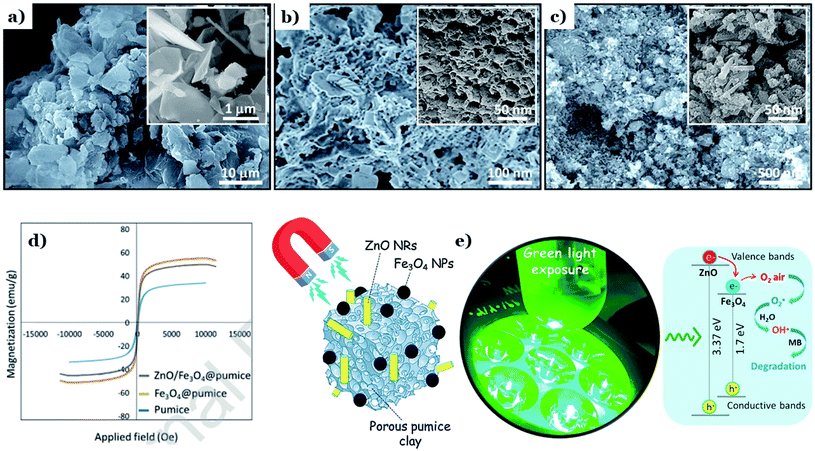 | ||
| Fig. 19 FE-SEM images of: natural pumice powder (a and b), and ZnO/Fe3O4@pumice composite (c); room temperature magnetic–hysteresis (M–H) curves of the natural pumice, Fe3O4@pumice, and ZnO/Fe3O4@pumice composite (d); schematic of synergistic photocatalytic process, executed by ZnO/Fe3O4@pumice composite and green light irradiation (e). This figure has been reproduced (adapted) from ref. 127 with permission from Elsevier, copyright 2020. | ||
5. Future prospective
With a novel concept of treating waste by waste, the utilization of green materials and the evolution of green materials-based metal oxides in the field of photocatalysis offer innovative and powerful technologies, resulting in sustainable water pollution control. However, several current research gaps that may be worthy of deeper research in the future are recommended as follows:Firstly, most of the current relevant works are lab-scale studies. Therefore, further investigations need to extend the large-scale applications, thus gradually bridging the gap between lab and industry. In addition, it is imperative to start investigating the economic feasibility. These will give a basis for this technique to be scaled up for industrial applications purposes.
Secondly, it is imperative to enhance the photocatalytic activities of metal oxide-based photocatalysts. So far, great efforts have been spent on using FA, FS, clay, and pumice as efficient supporting materials for fixing metal oxides. In fact, these materials can also become the main photocatalysts as their components contain a certain amount of metal oxides such as Al2O3, Fe2O3, TiO2, and ZnO. These components can act as semiconductor photocatalysts under light irradiation. Thus, more studies are needed to explore the potential of green materials as main photocatalysts.
Importantly, more research is also needed to combine single materials together to promote overall efficiency. Each material has distinct outstanding properties and therefore combining these single materials together is wise cooperation to enhance the overall photocatalytic efficiency. For example, the presence of FA or FS provides an ideal in situ iron source for Fenton oxidation. Thus, any combination with FA or FS can lead to dual effects (photocatalysis and Fenton oxidation).
Another point is that there is no report for photodegradation of contaminants in actual drinking water using green materials-based metal oxides. Most relevant reports aim to organic compounds removal in wastewater. In that context, the photocatalytic activities of green materials-based metal oxides should be further tested for the on-site treatment of real wastewater (e.g., industrial and household effluents). It would be of great value for large-scale applications.
In addition, the effects of initial compositions and properties of natural/waste materials on the as-synthesized catalysts are required to discover in further works. Notably, the use of materials that contain harmful substances (e.g., heavy metals) may leads to environmental risks.
Last, according to current results, the photodegradation efficiency of various pollutants using green materials-based metal oxides is rarely 100%. It is recommended to explore the intermediates during the degradation pathway of pollutants. Several intermediates are toxic and therefore it is a must to remove completely these products. Further studies need to be improved to study the complete degradation of pollutants.
6. Conclusion
Photocatalysis offers an alternative advanced approach to conventional wastewater treatment methods that can completely mineralize and degrade recalcitrant pollutants into harmless constituents. In the photocatalysis process, nanostructured metal oxides are the frontliners in the decomposition of organic compounds. Metal oxide-based materials possess exceptional physicochemical properties which make them promising candidates for the removal of a variety of pollutants such as dyes, pharmaceuticals, bacteria, and volatile organic compounds. However, inefficient recovery and reuse of most metal oxides in particles or powder are the foremost hindrances that need to be tackled to make this material viable for scale-up on industrial applications. In an effort towards overcoming this matter, scientists have started to incorporate metal oxide-based semiconductors on support materials, aiming to provide continuous operation for multiple cycles. Inspired by this, green materials comprising natural materials (clay mineral and pumice) and waste materials (ash and foundry sand) have been investigated as eco-friendlier alternatives in the realm of immobilized photocatalysts for environmental remediation. In this contribution, fundamental principles, mechanism of photocatalysis, and current challenges towards using metal oxide as semiconductors have been described. In addition, common immobilization techniques adopted are summarized in detail. Sources, classifications, the properties, and chemical composition of ash, clay mineral, foundry sand, and pumice are systematically introduced. Last, we highlighted recent advances in applications of green materials-based metal oxides composite for the photodegradation of various pollutants.Conclusively, in terms of environmental aspects, the reuse of FA and FS for degradation of contaminants possess more environmental benefits as these two materials are wastes from coal-based thermal power plants and the ferrous and nonferrous metal casting industry, respectively. Clay and pumice are present in unlimited quantity in nature, especially areas around volcanic (pumice) and the ground where rivers or streams once flowed (clay). Hence, the collection of clay and pumice is easier and more convenient. However, when considering the feasibility for industrial scale-up, the reuse of FA and FS is more feasible due to the concentration and continuity of the raw material source (or industrial wastes). In terms of economic feasibility, the use of the aforementioned materials is considered an ideal approach to reduce the relevant costs, such as the cost of the raw materials and waste disposal costs. In terms of efficiency in heterogeneous photocatalytic reactions, all materials exhibited their potential applications as efficient supporting materials through our analysis and assessment based on relevant reports (Section 3). Amongst the four types of materials, FA possesses a very high surface area and pore volume, thus enhancing remarkably its adsorption capacity. In this way, FA can serve as a low-cost adsorbent that attracts pollutant molecules, followed by photocatalytic reactions carried out by metal oxides. Similarly, highly porosity (∼90%) and the amorphous nature are unique properties of pumice, which contribute to the formation of its high specific surface area and skeleton structure consisting of many empty pores that can act as channels to transport substances like water and ions. The high content of silica results in a negative charge on the surface of pumice and therefore it has an excellent ability to absorb pollutant molecules. The most unique property of clay is its high mechanical strength, and this indirectly improved the reusability and durability of photocatalyst systems. Owing to small particles and unique crystal structures, clay mostly acts as a durable binding material that efficiently supports metal oxide nanoparticles. Last, the binding properties of FS make it promising support materials for metal oxides in heterogeneous photocatalysis reactions. Notably, FS and FA are constituted by a considerable amount of iron oxides and therefore they can play a dual role. This means they can serve as an in situ iron source for Fenton oxidation and also efficient support materials for photocatalytic reactions. This interesting combination promotes to synergistic effect for the decomposition of pollutants from an aqueous solution. Generally, among the aforementioned materials, different materials possess distinct advantages. Thus, recent efforts have been made to combine single materials together to promote overall efficiency. For example, FA, FS, and clay are used to fabricate unique composites, in which clay acts as a binding material, while FS and FA can serve as an in situ iron source, as discussed in Section 4.3.
Conflicts of interest
The authors declare no conflicts of interest.Acknowledgements
The authors gratefully acknowledge Thu Dau Mot University for the financial support and required journal access during the construction of this work.References
- K. Sharma, V. Dutta, S. Sharma, P. Raizada, A. Hosseini-Bandegharaei, P. Thakur and P. Singh, J. Ind. Eng. Chem., 2019, 78, 1–20 CrossRef CAS.
- A. Thirunavukkarasu, R. Nithya and R. Sivashankar, Rev. Environ. Sci. Biotechnol., 2020, 1–28 Search PubMed.
- A. O. Adeogun, O. R. Ibor, S. D. Adeduntan and A. Arukwe, Sci. Total Environ., 2016, 541, 372–382 CrossRef CAS PubMed.
- A. Inyinbor Adejumoke, O. Adebesin Babatunde, P. Oluyori Abimbola, A. Adelani Akande Tabitha, O. Dada Adewumi and A. Oreofe Toyin, Water Challenges of an Urbanizing World, 2018, 33 Search PubMed.
- A. M. Briggs, M. J. Cross, D. G. Hoy, L. Sanchez-Riera, F. M. Blyth, A. D. Woolf and L. March, Gerontologist, 2016, 56, S243–S255 CrossRef PubMed.
- S. Wang, Y. Hu and J. Wang, J. Environ. Manage., 2018, 217, 240–246 CrossRef CAS PubMed.
- J. B. Sluiter, R. O. Ruiz, C. J. Scarlata, A. D. Sluiter and D. W. Templeton, J. Agric. Food Chem., 2010, 58, 9043–9053 CrossRef CAS PubMed.
- T. Hou, H. Du, Z. Yang, Z. Tian, S. Shen, Y. Shi, W. Yang and L. Zhang, Sep. Purif. Technol., 2019, 223, 123–132 CrossRef CAS.
- M. Kamrani and A. Akbari, J. Environ. Chem. Eng., 2018, 6, 583–587 CrossRef CAS.
- G. Crini and E. Lichtfouse, Environ. Chem. Lett., 2019, 17, 145–155 CrossRef CAS.
- N. Suriyanon, J. Permrungruang, J. Kaosaiphun, A. Wongrueng, C. Ngamcharussrivichai and P. Punyapalakul, Chemosphere, 2015, 136, 222–231 CrossRef CAS PubMed.
- J. Ouyang, L. Zhou, Z. Liu, J. Y. Heng and W. Chen, Sep. Purif. Technol., 2020, 253, 117536 CrossRef CAS.
- B. Srikanth, R. Goutham, R. B. Narayan, A. Ramprasath, K. Gopinath and A. Sankaranarayanan, J. Environ. Manage., 2017, 200, 60–78 CrossRef CAS PubMed.
- Y. Deng and R. Zhao, Curr. Pollut. Rep., 2015, 1, 167–176 CrossRef CAS.
- N. Daneshvar, S. Aber, M. S. Dorraji, A. Khataee and M. Rasoulifard, Sep. Purif. Technol., 2007, 58, 91–98 CrossRef CAS.
- Y. Abdollahi, A. H. Abdullah, Z. Zainal and N. A. Yusof, Int. J. Chem., 2011, 3, 31 CAS.
- Y. Song, Y. Peng, N. V. Long, Z. Huang and Y. Yang, Appl. Surf. Sci., 2021, 542, 148584 CrossRef CAS.
- T. S. Bui, P. Bansal, B.-K. Lee, T. Mahvelati-Shamsabadi and T. Soltani, Appl. Surf. Sci., 2020, 506, 144184 CrossRef CAS.
- N. V. Long, Y. Yang, T. Teranishi, C. M. Thi, Y. Cao and M. Nogami, Mater. Des., 2015, 86, 797–808 CrossRef CAS.
- L. Yang, Y. Yang, Y. Ma, S. Li, Y. Wei, Z. Huang and N. V. Long, Nanomaterials, 2017, 7, 398 CrossRef PubMed.
- A. B. Djurišić, Y. H. Leung and A. M. C. Ng, Mater. Horiz., 2014, 1, 400–410 RSC.
- R. Gusain, K. Gupta, P. Joshi and O. P. Khatri, Adv. Colloid Interface Sci., 2019, 272, 102009 CrossRef CAS PubMed.
- N. V. Long, Y. Yang, C. M. Thi, Y. Cao and M. Nogami, Colloids Surf., A, 2014, 456, 184–194 CrossRef.
- I.-S. Kim, M. Baek and S.-J. Choi, J. Nanosci. Nanotechnol., 2010, 10, 3453–3458 CrossRef CAS PubMed.
- M. Premanathan, K. Karthikeyan, K. Jeyasubramanian and G. Manivannan, Nanomedicine, 2011, 7, 184–192 CrossRef CAS PubMed.
- W. Song, J. Zhang, J. Guo, J. Zhang, F. Ding, L. Li and Z. Sun, Toxicol. Lett., 2010, 199, 389–397 CrossRef CAS PubMed.
- W. F. Vevers and A. N. Jha, Ecotoxicology, 2008, 17, 410–420 CrossRef CAS PubMed.
- N. A. Putri, V. Fauzia, S. Iwan, L. Roza, A. A. Umar and S. Budi, Appl. Surf. Sci., 2018, 439, 285–297 CrossRef CAS.
- Y. Li, X. Li, J. Li and J. Yin, Water Res., 2006, 40, 1119–1126 CrossRef CAS PubMed.
- D. Hanaor, M. Michelazzi, J. Chenu, C. Leonelli and C. C. Sorrell, J. Eur. Ceram. Soc., 2011, 31, 2877–2885 CrossRef CAS.
- A. Corma and H. Garcia, Chem. Commun., 2004, 1443–1459 RSC.
- N. Todorova, T. Giannakopoulou, S. Karapati, D. Petridis, T. Vaimakis and C. Trapalis, Appl. Surf. Sci., 2014, 319, 113–120 CrossRef CAS.
- Y. Yan, X. Zhou, J. Lan, Z. Li, T. Zheng, W. Cao, N. Zhu and W. Liu, J. Photochem. Photobiol., A, 2018, 367, 355–364 CrossRef CAS.
- L. Bruner and J. Kozak, Z. Elektrochem. Angew. Phys. Chem., 1911, 17, 354–360 CAS.
- A. Eibner, Chem.-Ztg., 1911, 35, 753–755 CAS.
- J. M. Coronado, F. Fresno, M. D. Hernández-Alonso and R. Portela, Design of advanced photocatalytic materials for energy and environmental applications, Springer, 2013 Search PubMed.
- E. Baur and A. Perret, Helv. Chim. Acta, 1924, 7, 910–915 CrossRef CAS.
- C. F. Goodeve and J. A. Kitchener, Trans. Faraday Soc., 1938, 34, 902–908 RSC.
- P. Lotfabadi, Renewable Sustainable Energy Rev., 2015, 52, 1340–1353 CrossRef.
- Q. Guo, C. Zhou, Z. Ma and X. Yang, Adv. Mater., 2019, 31, 1901997 CrossRef CAS PubMed.
- P. Boddy, J. Electrochem. Soc., 1968, 115, 199 CrossRef CAS.
- A. Fujishima and K. Honda, Nature, 1972, 238, 37–38 CrossRef CAS PubMed.
- T. Inoue, A. Fujishima, S. Konishi and K. Honda, Nature, 1979, 277, 637–638 CrossRef CAS.
- Z. Long, Q. Li, T. Wei, G. Zhang and Z. Ren, J. Hazard. Mater., 2020, 395, 122599 CrossRef CAS PubMed.
- A. Gołąbiewska, M. P. Kobylański and A. Zaleska-Medynska, in Metal Oxide-Based Photocatalysis, ed. A. Zaleska-Medynska, Elsevier, 2018, pp. 3–50, DOI:10.1016/B978-0-12-811634-0.00002-0.
- M. E. Khan, M. M. Khan and M. H. Cho, New J. Chem., 2015, 39, 8121–8129 RSC.
- R. Saravanan, F. Gracia and A. Stephen, in Nanocomposites for visible light-induced photocatalysis, Springer, 2017, pp. 19–40 Search PubMed.
- M. A. Lazar, S. Varghese and S. S. Nair, Catalysts, 2012, 2, 572–601 CrossRef CAS.
- U. Ashik, S. Kudo and J.-i. Hayashi, Synthesis of Inorganic Nanomaterials, 2018, pp. 19–57 Search PubMed.
- J. A. Rodríguez and M. Fernández-García, Synthesis, properties, and applications of oxide nanomaterials, John Wiley & Sons, 2007 Search PubMed.
- G. Mavrou, S. Galata, P. Tsipas, A. Sotiropoulos, Y. Panayiotatos, A. Dimoulas, E. Evangelou, J. W. Seo and C. Dieker, J. Appl. Phys., 2008, 103, 014506 CrossRef.
- M. M. Khan, S. F. Adil and A. Al-Mayouf, J. Saudi Chem. Soc., 2015, 19, 462–464 CrossRef.
- S. H. S. Chan, T. Y. Wu, J. C. Juan and C. Y. Teh, J. Chem. Technol. Biotechnol., 2011, 86, 1130–1158 CrossRef CAS.
- T. Velempini, E. Prabakaran and K. Pillay, Mater. Today Chem., 2021, 19, 100380 CrossRef CAS.
- X. Liu, J. Iocozzia, Y. Wang, X. Cui, Y. Chen, S. Zhao, Z. Li and Z. Lin, Energy Environ. Sci., 2017, 10, 402–434 RSC.
- H. Lv, Y. Guo, Z. Yang, Y. Cheng, L. P. Wang, B. Zhang, Y. Zhao, Z. J. Xu and G. Ji, J. Mater. Chem. C, 2017, 5, 491–512 RSC.
- M. G. Lee, J. S. Park and H. W. Jang, J. Korean Ceram. Soc., 2018, 55, 185–202 CrossRef CAS.
- R. Medhi, M. D. Marquez and T. R. Lee, ACS Appl. Nano Mater., 2020, 3, 6156–6185 CrossRef CAS.
- H. Tada, Q. Jin, A. Iwaszuk and M. Nolan, J. Phys. Chem. C, 2014, 118, 12077–12086 CrossRef CAS.
- C. A. Linkous, G. J. Carter, D. B. Locuson, A. J. Ouellette, D. K. Slattery and L. A. Smitha, Environ. Sci. Technol., 2000, 34, 4754–4758 CrossRef CAS.
- D. Wodka, E. Bielanska, R. P. Socha, M. Elzbieciak-Wodka, J. Gurgul, P. Nowak, P. Warszyński and I. Kumakiri, ACS Appl. Mater. Interfaces, 2010, 2, 1945–1953 CrossRef CAS PubMed.
- J. Zeng, S. Liu, J. Cai and L. Zhang, J. Phys. Chem. C, 2010, 114, 7806–7811 CrossRef CAS.
- A. Sraw, T. Kaur, Y. Pandey, A. Sobti, R. K. Wanchoo and A. P. Toor, J. Environ. Chem. Eng., 2018, 6, 7035–7043 CrossRef CAS.
- M. Visa and A. Duta, Chem. Eng. J., 2013, 223, 860–868 CrossRef CAS.
- K. V. S. Rao, A. Rachel, M. Subrahmanyam and P. Boule, Appl. Catal., B, 2003, 46, 77–85 CrossRef.
- M.-T. Nguyen-Dinh, T. S. Bui, P. Bansal, M. Jourshabani and B.-K. Lee, Sep. Purif. Technol., 2021, 267, 118607 CrossRef CAS.
- P. Bansal, T. S. Bui and B.-K. Lee, Chem. Eng. J., 2020, 391, 123509 CrossRef CAS.
- H. I. De Lasa, B. Serrano and M. Salaices, Photocatalytic reaction engineering, Springer, 2005 Search PubMed.
- F. Adam, J. N. Appaturi, R. Thankappan and M. A. M. Nawi, Appl. Surf. Sci., 2010, 257, 811–816 CrossRef CAS.
- M. Shaban, M. R. Abukhadra, A. Hamd, R. R. Amin and A. A. Khalek, J. Environ. Manage., 2017, 204, 189–199 CrossRef CAS PubMed.
- J. Lv, T. Sheng, L. Su, G. Xu, D. Wang, Z. Zheng and Y. Wu, Appl. Surf. Sci., 2013, 284, 229–234 CrossRef CAS.
- A. N. Ökte and D. Karamanis, Appl. Catal., B, 2013, 142, 538–552 CrossRef.
- J. Zhang, H. Cui, B. Wang, C. Li, J. Zhai and Q. Li, Chem. Eng. J., 2013, 223, 737–746 CrossRef CAS.
- L. Lin, M. Huang, L. Long and D. Chen, J. Alloys Compd., 2014, 615, 929–932 CrossRef CAS.
- G. Asgari, S. Akbari, A. M. S. Mohammadi, A. Poormohammadi and B. Ramavandi, Data Brief, 2017, 13, 132–136 CrossRef PubMed.
- N. Setthaya, P. Chindaprasirt, S. Yin and K. Pimraksa, Powder Technol., 2017, 313, 417–426 CrossRef CAS.
- B. Pant, G. P. Ojha, H.-Y. Kim, M. Park and S.-J. Park, Environ. Pollut., 2019, 245, 163–172 CrossRef CAS PubMed.
- W.-K. Huang, K.-J. Chung, Y.-M. Liu, M.-D. Ger, N.-W. Pu and M.-J. Youh, Vacuum, 2015, 118, 94–99 CrossRef CAS.
- X. Cui, J. Shi, Z. Ye, Z. Zhang, B. Xu and S. Chen, Int. J. Photoenergy, 2014, 2014, 823078 CrossRef.
- D. Levy and M. Zayat, The Sol-Gel Handbook, 3 Volume Set: Synthesis, Characterization, and Applications, John Wiley & Sons, 2015 Search PubMed.
- P. Lum, K. Foo, N. Zakaria and P. Palaniandy, Mater. Chem. Phys., 2020, 241, 122405 CrossRef CAS.
- S. Esposito, Materials, 2019, 12, 668 CrossRef CAS PubMed.
- P. Huo, Y. Yan, S. Li, H. Li and W. Huang, Desalination, 2010, 256, 196–200 CrossRef CAS.
- B. Wang, Q. Li, W. Wang, Y. Li and J. Zhai, Appl. Surf. Sci., 2011, 257, 3473–3479 CrossRef CAS.
- I. Fatimah, A. Said and U. A. Hasanah, Bull. Chem. React. Eng. Catal., 2015, 10, 43–49 CAS.
- J. Song, X. Wang, Y. Bu, X. Wang, J. Zhang, J. Huang, R. Ma and J. Zhao, Appl. Surf. Sci., 2017, 391, 236–250 CrossRef CAS.
- A. Rapsomanikis, D. Papoulis, D. Panagiotaras, E. Kaplani and E. Stathatos, Global NEST J., 2014, 16, 485–498 Search PubMed.
- C. R. S. de Oliveira, M. A. Batistella, A. A. U. de Souza and S. M. d. A. G. Ulson, Powder Technol., 2021, 381, 366–380 CrossRef CAS.
- A. Ökte, D. Karamanis and D. Tuncel, Catal. Today, 2014, 230, 205–213 CrossRef.
- H. Chen, L. Zhao, Y. Xiang, Y. He, G. Song, X. Wang and F. Liang, Desalin. Water Treat., 2016, 57, 9660–9670 CrossRef CAS.
- A. Kashyap, N. K. Singh, M. Soni and A. Soni, in Chemical Solution Synthesis for Materials Design and Thin Film Device Applications, Elsevier, 2021, pp. 79–117 Search PubMed.
- P. Sujaridworakun, S. Jinawath, W. Panpa, A. Nakajima and M. Yoshimura, in Key Engineering Materials, Trans Tech Publications Ltd, 2007, vol. 352, pp. 281–285 Search PubMed.
- P. Esparza, M. Borges, L. Díaz, M. Alvarez-Galván and J. Fierro, Appl. Catal., A, 2010, 388, 7–14 CrossRef CAS.
- M. Visa, L. Andronic, D. Lucaci and A. Duta, Adsorption, 2011, 17, 101–108 CrossRef CAS.
- L. H. Slewa, T. A. Abbas and N. M. Ahmed, J. Mater. Sci.: Mater. Electron., 2019, 30, 11193–11207 CrossRef CAS.
- M. Joshi and B. Butola, in Advances in the dyeing and finishing of technical textiles, Elsevier, 2013, pp. 355–411 Search PubMed.
- K. Kakaei, M. D. Esrafili and A. Ehsani, in Interface science and technology, Elsevier, 2019, vol. 27, pp. 303–337 Search PubMed.
- D. Lončarević and Ž. Čupić, in Industrial Applications of Nanomaterials, Elsevier, 2019, pp. 91–122 Search PubMed.
- D. Grosso, J. Mater. Chem., 2011, 21, 17033–17038 RSC.
- A. V. Rane, K. Kanny, V. Abitha and S. Thomas, in Synthesis of inorganic nanomaterials, Elsevier, 2018, pp. 121–139 Search PubMed.
- U. Ashik and W. W. Daud, J. Taiwan Inst. Chem. Eng., 2016, 61, 247–260 CrossRef CAS.
- U. Ashik, W. W. Daud and J.-I. Hayashi, C. R. Chim., 2017, 20, 896–909 CrossRef CAS.
- M. B. Tahir, M. Rafique, M. S. Rafique, T. Nawaz, M. Rizwan and M. Tanveer, in Nanotechnology and Photocatalysis for Environmental Applications, Elsevier, 2020, pp. 119–138 Search PubMed.
- T. V. Gavrilović, D. J. Jovanović and M. D. Dramićanin, in Nanomaterials for green Energy, Elsevier, 2018, pp. 55–81 Search PubMed.
- D. S. Jung, Y. N. Ko, Y. C. Kang and S. B. Park, Adv. Powder Technol., 2014, 25, 18–31 CrossRef CAS.
- J. Zhang, W. Bing, C. Hao, L. Chuang, Z. Jianping and L. Qin, J. Rare Earths, 2014, 32, 1120–1125 CrossRef CAS.
- R. A. O'Connor, P. A. Cahill and G. B. McGuinness, in Biomaterials for Organ and Tissue Regeneration, Elsevier, 2020, pp. 249–272 Search PubMed.
- Y. Zheng, Bioinspired Design of Materials Surfaces, Elsevier, 2019 Search PubMed.
- M. E. Hoque, T. Nuge, T. K. Yeow and N. Nordin, Nanostructured Polymer Composites for Biomedical Applications, 2019, pp. 87–104 Search PubMed.
- P. S. Saud, B. Pant, M. Park, S.-H. Chae, S.-J. Park, E.-N. Mohamed, S. S. Al-Deyab and H.-Y. Kim, Ceram. Int., 2015, 41, 1771–1777 CrossRef CAS.
- Y. Zheng, in Bioinspired Design of Materials Surfaces, ed. Y. Zheng, Elsevier, 2019, pp. 99–146 Search PubMed.
- J. Zhu, S. Liu, J. Ge, X. Guo, X. Wang and H. Wu, Res. Chem. Intermed., 2016, 42, 3637–3654 CrossRef CAS.
- H. Kim and C. Kim, Dig. J. Nanomater. Biostructures, 2014, 9, 997–1006 Search PubMed.
- V. Gilja, Z. Katančić, L. K. Krehula, V. Mandić and Z. Hrnjak-Murgić, Sci. Eng. Compos. Mater., 2019, 26, 292–300 CAS.
- D. Chen, Q. Zhu, F. Zhou, X. Deng and F. Li, J. Hazard. Mater., 2012, 235, 186–193 CrossRef PubMed.
- K.-i. Katsumata, X. Hou, M. Sakai, A. Nakajima, A. Fujishima, N. Matsushita, K. J. MacKenzie and K. Okada, Appl. Catal., B, 2013, 138, 243–252 CrossRef.
- D. Papoulis, S. Komarneni, D. Panagiotaras, E. Stathatos, K. C. Christoforidis, M. Fernández-García, H. Li, Y. Shu, T. Sato and H. Katsuki, Appl. Catal., B, 2014, 147, 526–533 CrossRef CAS.
- A. H. Zyoud, S. Asaad, S. H. Zyoud, S. H. Zyoud, M. H. Helal, N. Qamhieh, A. Hajamohideen and H. S. Hilal, J. Environ. Chem. Eng., 2020, 8, 104227 CrossRef CAS.
- A. Zyoud, T. Zorba, M. Helal, S. Zyoud, N. Qamhiya, A. Hajamohideen, S. Zyoud and H. Hilal, Int. J. Environ. Sci. Technol., 2019, 16, 6267–6276 CrossRef CAS.
- Y. Zhang, H. Gan and G. Zhang, Chem. Eng. J., 2011, 172, 936–943 CrossRef CAS.
- P. Bansal and A. Verma, Mater. Des., 2017, 125, 135–145 CrossRef CAS.
- S. Talwar, A. K. Verma and V. K. Sangal, Chem. Eng. J., 2020, 382, 122772 CrossRef CAS.
- P. Bansal and A. Verma, J. Photochem. Photobiol., A, 2017, 342, 131–142 CrossRef CAS.
- P. Bansal and A. Verma, Chemosphere, 2018, 212, 611–619 CrossRef CAS PubMed.
- P. Bansal, A. Verma, C. Mehta and V. K. Sangal, J. Environ. Manage., 2019, 233, 793–801 CrossRef CAS PubMed.
- X.-Y. Chuan, M. Hirano and M. Inagaki, Appl. Catal., B, 2004, 51, 255–260 CrossRef CAS.
- R. Taheri-Ledari, K. Valadi, S. Gharibi and A. Maleki, Mater. Res. Bull., 2020, 130, 110946 CrossRef CAS.
- A. S. Yusuff, L. T. Popoola and E. I. Aderibigbe, J. Environ. Chem. Eng., 2020, 8, 103907 CrossRef CAS.
- L. Shao, H. Liu, W. Zeng, C. Zhou, D. Li, L. Wang, Y. Lan, F. Xu and G. Liu, Appl. Surf. Sci., 2019, 478, 1017–1026 CrossRef CAS.
- H. J. Kim, H. R. Pant, N. J. Choi and C. S. Kim, Chem. Eng. J., 2013, 230, 244–250 CrossRef CAS.
- M. Visa, C. Bogatu and A. Duta, Appl. Surf. Sci., 2010, 256, 5486–5491 CrossRef CAS.
- V. C. Pandey, Phytomanagement of Fly Ash, Elsevier, 2020 Search PubMed.
- D. An, Y. Guo, B. Zou, Y. Zhu and Z. Wang, Biomass Bioenergy, 2011, 35, 1227–1234 CrossRef CAS.
- R. Blissett and N. Rowson, Fuel, 2012, 97, 1–23 CrossRef CAS.
- M. Borges, M. Alvarez-Galván, P. Esparza, E. Medina, P. Martín-Zarza and J. Fierro, Energy Environ. Sci., 2008, 1, 364–369 RSC.
- A. Daifullah, B. Girgis and H. Gad, Mater. Lett., 2003, 57, 1723–1731 CrossRef CAS.
- E. Temeche, M. Yu and R. M. Laine, Green Chem., 2020, 22, 4656–4668 RSC.
- P. Sultana, S. Das, A. Bhattacharya, R. Basu and P. Nandy, Int. J. Appl. Ceram. Technol., 2013, 10, 939–948 CrossRef CAS.
- B. Szczepanik, Appl. Clay Sci., 2017, 141, 227–239 CrossRef CAS.
- J. Liu and G. Zhang, Phys. Chem. Chem. Phys., 2014, 16, 8178–8192 RSC.
- C. Ooka, S. Akita, Y. Ohashi, T. Horiuchi, K. Suzuki, S.-i. Komai, H. Yoshida and T. Hattori, J. Mater. Chem., 1999, 9, 2943–2952 RSC.
- Y. Dong, Z. Liu and L. Chen, J. Radioanal. Nucl. Chem., 2012, 292, 435–443 CrossRef CAS.
- C. H. Zhou, Appl. Clay Sci., 2011, 53, 87–96 CrossRef CAS.
- N. Jagtap and V. Ramaswamy, Appl. Clay Sci., 2006, 33, 89–98 CrossRef CAS.
- M. Albdiry and B. Yousif, Mater. Des., 2014, 57, 279–288 CrossRef CAS.
- S. Ng and J. Plank, Cem. Concr. Res., 2012, 42, 847–854 CrossRef CAS.
- E. Paineau, Appl. Sci., 2018, 8, 1921 CrossRef.
- S. Mustapha, M. Ndamitso, A. Abdulkareem, J. Tijani, D. Shuaib, A. Ajala and A. Mohammed, Appl. Water Sci., 2020, 10, 1–36 CrossRef.
- G. V. Oliveira, W. L. Da Silva, E. R. de Oliveira, M. A. Lansarin and J. H. dos Santos, Water, Air, Soil Pollut., 2016, 227, 1–11 CrossRef CAS.
- J. Hashim, L. Looney and M. Hashmi, J. Mater. Process. Technol., 2002, 123, 251–257 CrossRef CAS.
- R. Siddique and G. Singh, Resour., Conserv. Recycl., 2011, 55, 885–892 CrossRef.
- R. Siddique and A. Mehta, in Nonconventional and Vernacular Construction Materials, Elsevier, 2020, pp. 247–303 Search PubMed.
- K.-L. Lin, C.-J. Cheng, A. Cheng and S.-J. Chao, Sustainable Environ. Res., 2012, 22, 91–97 CAS.
- A. Arulrajah, E. Yaghoubi, M. Imteaz and S. Horpibulsuk, Sustain. Cities Soc., 2017, 28, 343–349 CrossRef.
- G. Asgari, B. Roshani and G. Ghanizadeh, J. Hazard. Mater., 2012, 217, 123–132 CrossRef PubMed.
- K. Valadi, S. Gharibi, R. Taheri-Ledari and A. Maleki, Solid State Sci., 2020, 101, 106141 CrossRef CAS.
- P. Calabrò, N. Moraci and P. Suraci, J. Hazard. Mater., 2012, 207, 111–116 CrossRef PubMed.
- D. İ. Çifçi and S. Meriç, Desalin. Water Treat., 2016, 57, 18131–18143 CrossRef.
- N. Moraci and P. S. Calabrò, J. Environ. Manage., 2010, 91, 2336–2341 CrossRef CAS PubMed.
- M. N. Sepehr, A. Amrane, K. A. Karimaian, M. Zarrabi and H. R. Ghaffari, J. Taiwan Inst. Chem. Eng., 2014, 45, 635–647 CrossRef CAS.
- M. Kitis, E. Karakaya, N. O. Yigit, G. Civelekoglu and A. Akcil, Water Res., 2005, 39, 1652–1662 CrossRef CAS PubMed.
- F. Akbal, J. Environ. Manage., 2005, 74, 239–244 CrossRef CAS PubMed.
- M. C. Álvarez-Galván, A. Brito, F. J. García-Álvarez, A. Víctor, E. Borges and B. Pawelec, Appl. Catal., A, 2008, 350, 38–45 CrossRef.
- T. Liu, Z.-L. Wang, X. Yan and B. Zhang, Chem. Eng. J., 2014, 245, 34–40 CrossRef CAS.
- M. R. Samarghandi, M. Zarrabi, A. Amrane, G. H. Safari and S. Bashiri, Iran. J. Environ. Health Sci. Eng., 2012, 9, 1–10 CrossRef PubMed.
- A. Rachel, B. Lavedrine, M. Subrahmanyam and P. Boule, Catal. Commun., 2002, 3, 165–171 CrossRef CAS.
| This journal is © The Royal Society of Chemistry 2021 |

