
 Open Access Article
 This Open Access Article is licensed under a Creative Commons Attribution-Non Commercial 3.0 Unported Licence
Synthesis of holey graphene for advanced nanotechnological applications
Nitul S. Rajput *a,
Shroq Al Zadjalia,
Monserrat Gutierreza,
Amal M. K. Esawi*b and
Mohamed Al Teneijia
*a,
Shroq Al Zadjalia,
Monserrat Gutierreza,
Amal M. K. Esawi*b and
Mohamed Al Teneijia
aAdvanced Materials Research Center, Technology Innovation Institute, Building B04C, Abu Dhabi 9639, United Arab Emirates. E-mail: nitul.rajput@tii.ae
bDepartment of Mechanical Engineering, School of Sciences and Engineering, The American University in Cairo, Cairo, 11835, Egypt. E-mail: a_esawi@aucegypt.edu
First published on 12th August 2021
Abstract
Holey or porous graphene, a structural derivative of graphene, has attracted immense attention due to its unique properties and potential applications in different branches of science and technology. In this review, the synthesis methods of holey or porous graphene/graphene oxide are systematically summarized and their potential applications in different areas are discussed. The process–structure–applications are explained, which helps relate the synthesis approaches to their corresponding key applications. The review paper is anticipated to benefit the readers in understanding the different synthesis methods of holey graphene, their key parameters to control the pore size distribution, advantages and limitations, and their potential applications in various fields.
1. Introduction
Graphene is a remarkable material with excellent material properties such as high thermal and electrical conductivity, high electron mobility and Young's modulus.1–3 However, the real-world or commercial applications of graphene have been limited partly due to its zero band gap nature, which is considered a bottleneck for its application in the semiconductor industry and partly due to the complexity in the production of high-quality graphene economically.4 Heterostructure devices such as graphene–hBN and graphene–MoS2/WS2, made of graphene as one of the components, have been rising to make profound use of the properties of graphene.5–9 Another development that recently came out in the field of graphene is holey/porous graphene, which is considered a unique structural derivative of graphene/GO. Fig. 1a is a chart that shows the increasing number of publications focused on holey graphene in the past few years. The trend indicates a growing interest in the material due to its unique properties and versatile nature, and potential application in different branches of science and technology. Holey graphene (HG) is defined as a graphene material with a large number of holes or pores on its basal plane. The pore sizes can vary from a few nm to few tens of nm to few microns in size and can be created by various methods and techniques. The schematic picture (Fig. 1b) shows a few graphene layers with arbitrarily distributed pores on their basal planes. HG sheets, when assembled to form a 3D porous material, is then called ‘porous graphene’;10,11 thus, HG can be considered as a sub-category of ‘porous graphene’. However, to have a comprehensive understanding of the synthesis processes and due to their similar properties and structural nature, by HG, we refer to both types of materials in this article. As indicated in the schematic Fig. 1, the irregularly arranged pores on the sheets form 3D channels. These 3D channels make a path for ions and other molecules to move around. In graphene sheets without pores (graphite), any ion or molecule will have two degrees of freedom. On the other hand, due to the presence of pores, ions and molecules will have three degrees of freedom in the HG material. Thus, graphene sheets with holes have the advantage of efficient ion transport even when the sheets are stacked.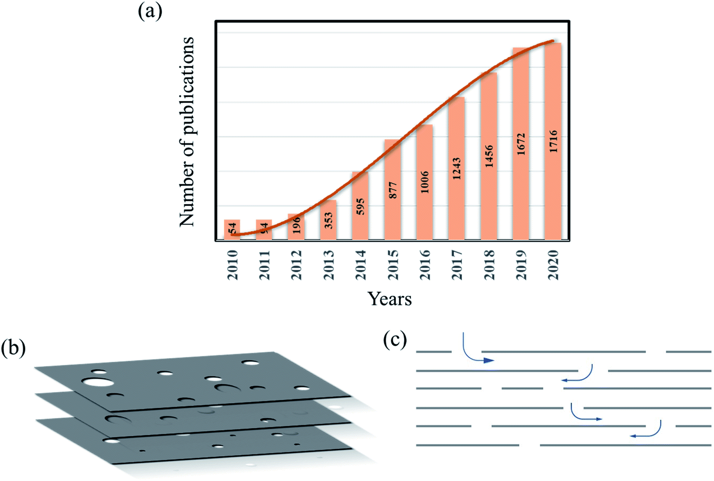 | ||
| Fig. 1 (a) The chart shows the number of publications focused on holey/porous graphene in the last ten years (data obtained from Scopus). (b) The schematic image shows the presence of nanoscale pores in a stack of graphene sheets. (c) The cross-sectional schematic view shows the interlayer channels formed in a stack of graphene sheets due to randomly distributed pores. Ions or molecules with sizes lower than the pore sizes could pass through the material (shown by the arrows). | ||
Another aspect of holey graphene material is that due to the lack of continuous C atoms, interlayer attractive forces, i.e., the van der Waals interactions among the layers, become weak. This manifests itself in the increased interlayer distance among the sheets. The availability of a large number of pores and increased interlayer distance provide a boost to the ion movement and enhanced mass transport. This opens up a major application of holey/porous graphene in the area of water purification and desalination.12–16
The origin of the restacking or aggregation in graphite or multilayer graphene is due to van der Waals interactions among the graphene sheets/layers. This force is proportional to the overlapping surface area (S) and inverse power to the interlayer distance. Previous calculations indicated a fourth inverse power dependence;17 however, after semiempirical corrections made to the power law, the interaction shows a asymptotic third inverse power dependence.18 The inverse power value in the van der Waals force could also depend on the geometry of the two surfaces (e.g., parallel plate and sphere) as well as the interplanar distance between the two objects.19–21 In porous or holey graphene material, restacking could be avoided due to the lack of enough carbon atoms and hence the lack of sufficient van der Waals forces. The limited restacking and the presence of a high number of pores could result in higher ionic access to the surfaces and thus increased specific surface area.
In addition to the fascinating properties, as discussed above, it is also found that porous graphene could behave similar to a direct band gap semiconductor. A study reveals a band gap value of 2.35 eV for porous graphene.22 However, the value might depend on the computational method. Du et al. predicted a value of 3.2 eV from their density functional theory (DFT) calculations.23 Another study from first principles calculations estimates an optical band gap of 1.28 eV.24 The band gap is likely to be tuned with the size distribution of the pores in the material. Denis et al. investigated the impact of different type vacancies such as single, double, and Stone–Wales, on the electronic properties of monolayer and bilayer graphene.25 The DFT study revealed that the creation of a single vacancy in bilayer graphene could induce metallic properties in the material; Stone–Wales defects would not alter the electronic properties much; on the other hand, mono/bilayer graphene with double vacancies would behave as a semi-metallic. These studies reveal the possibility of tuning the electronic properties of graphene with different pore (vacancy) types and sizes. However, a systematic experimental investigation is required to properly tune the electronic properties and further utilization in designing optoelectronic devices.
Another aspect of pores in HG is the high degree of reactivity of the unsaturated pores due to which the pore edges could be naturally saturated. For example, an unsaturated pore can chemisorb gas molecules and could be used for gas sensing applications.26 A theoretical investigation on the reactivity of different types of defects was carried out.27 It was revealed that the reactivity would highly depend on the functional groups attached and the number of such attached groups. The study indicated that the reactivity would be higher for the lower binding energy of the functional group linked to the graphene sites.
Pores can also be created on sheets of other structural derivatives of graphene such as graphene oxide (GO) and reduced graphene oxide (rGO). This can also result in the formation of holey GO/rGO (HGO or HrGO). Similar to the case of HG, the presence of pores in GO/rGO can modify the intrinsic properties of GO/rGO and in many ways, HG or HGO/HrGO would have similar properties that could be useful in certain fields. Both GO and rGO have a large number functional groups that could attach to the carbon atoms in graphene. GO is a material with a high amount of oxygen attached to it in the form of carbonyl and hydroxyl groups and can be considered as the oxidized form of graphene. On the other hand, reduced graphene oxide, which is obtained after the reduction of GO, contains lesser number of functional groups as compared to GO. Thus, in contrast to pure HG materials that would not have any element other than carbon, HGO/HrGO would have a certain number of functional groups attached to the sheets. The structural difference among graphene, GO, and rGO can be understood from the schematic presented in Fig. 2. As indicated in the figure, graphene is a semi-metal with zero band gap. On the other hand, GO has a large number of carboxyl groups due to which it shows high band gap and rGO could behave like a semiconductor with variable band gap, depending on the amount of the attached functional groups. Thus, as compared to GO, which is an insulator in nature due to the presence of a large number of carboxyl groups, rGO would have some conductivity.
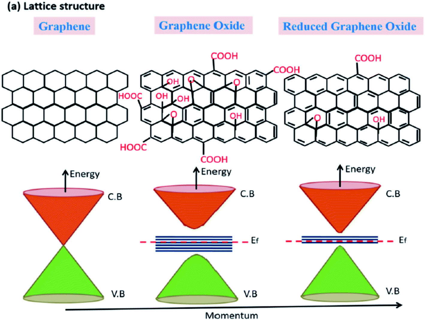 | ||
| Fig. 2 Schematic figure and the corresponding energy band diagram of graphene, GO, and rGO.32 | ||
The approximate interlayer distance in a few layers of graphene sheet is about 0.33 nm. In the case of GO, the oxygen containing functional groups could increase the thickness of single layer GO to 0.55 nm (theoretical value).28 However, in a multilayer GO sample, the interlayer distance could be 0.80–1.09 nm, which could vary largely depending on the amount of the attached functional groups.29 The interlayer distance in rGO is higher than the interlayer distance in graphene but lower than the interlayer distance of GO.30 The conductivity and the interlayer distance could be tuned by controlling the functional groups on the GO/rGO sample or the reduction process.31 These properties are summarized in Table 1.
| Properties | Graphene | Graphene oxide | Reduced graphene oxide |
|---|---|---|---|
| Synthesis | Chemical vapor deposition, thermal decomposition of silicon carbide (SiC), graphite exfoliation | Oxidation and exfoliation of graphite | Reduction of graphene oxide |
C![[thin space (1/6-em)]](https://www.rsc.org/images/entities/char_2009.gif) :O ratio :O ratio |
No oxygen | 2–4 | 8–246 |
| Interlayer distance (nm) | 0.33 | 0.80–1.09 | 0.35–0.45 |
| Young's modulus (TPa) | 1 | 0.2 | 0.25 |
| Electron mobility (cm2 V−1 s−1) | 10000–50000 |
Insulator | 0.05–200 |
| Production cost | High | Low | Low |
In addition to the properties mentioned above, GO or rGO can also provide high specific surface area; this property could be used in energy storage applications.35,36 The properties of GO or rGO can be further improved or modified by creating holes in the materials. Due to the presence of holes, and hence the increased number of edges, the catalytic property of holey GO (HGO) can be relatively higher than that of GO/rGO. Similar to HG, HGO/HrGO have also shown potential applications in the areas of energy storage, gas sensing, etc.37–41
HG, along with HGO/HrGO, has shown various interesting properties and various methods have been developed and implemented to synthesize or modify the materials for numerous applications. Due to the similar properties and applications of HG and HGO or HrGO by the term, HG we in general refer to HGO or HrGO along with holy/porous graphene. In this review, the main synthesis processes of HG and their major applications in different areas are discussed. HG is an emerging material; the synthesis and application of HG has been continuously evolving and various synthesis routes have been proposed in the recent few years as well as demonstrated to synthesize high quality holey/porous graphene. In recent years, articles focusing on different aspects of the material have been reported.42–45 This review presents a systematic understanding of different synthesis routes to obtain holey graphene, its properties, and key applications in different fields. The article is expected to benefit the community for understanding the synthesis methods of holey graphene, key parameters to control the pore size distribution, advantages and limitations of the methods, and their demonstrated applications in different fields. The article also presents a timely assessment to understand the current progress along with the recent trends and future opportunities.
2. Synthesis of holey graphene
Various methods have been developed by different research groups over the last few years in order to create or introduce holes on a graphene sheet or in a bulk graphene material. These methods can be categorized as physical, thermal, and chemical (Fig. 3). Energetic electron and ion beam can be used to remove carbon atoms from graphene sheets. This physical process is based on the energy and momentum transfer process from the charged particles to the carbon chains in the graphene sheet. An energetic electron or an ion can be generated in a typical scanning electron microscope (SEM), focused ion beam (FIB), or ion accelerator system. Pores can also be generated using chemical etching processes. The chemical methods can be further categorized into subcategories based on the approach. For example, chemical agents such as H2O2 and HNO3 can be directly used to create pores in graphene. Nanoparticles are also used as a catalyst for guided etching on the graphene sheets. Also, nanolithographic chemical methods are developed for pore creation, also known as the template-assisted approach. Template-based processes can provide the periodic formation of holes. Different approaches could produce pores of different sizes and retain certain advantages and disadvantages. The pores in graphene can be classified as microporous (<2 nm), mesoporous (2–50 nm), and macroporous (>50 nm) according to the definition by International Union of Pure and Applied Chemistry (IUPAC).46,47 In the following section, these synthesis methods are discussed in detail.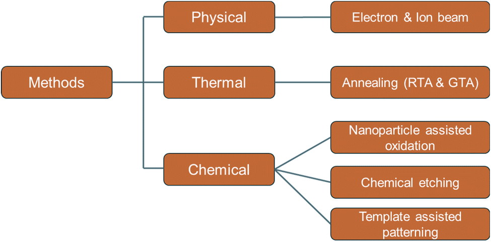 | ||
| Fig. 3 Different synthesis methods to create pores in graphene and GO/rGO materials. | ||
2.1 Physical: electron or ion beam irradiation
Micro/nano holes on a graphene sheet can be made by removing certain sets of carbon atoms. This can be achieved by passing energetic electrons or ion particles through the graphene sheet. The energetic particles transfer their momentum to the bonded carbon atoms. If the momentum transfer or transferred energy is more than the binding energy of the sp2 bonded carbon atoms, then those carbon atoms can be removed from the site.The fabrication of precise nanopores with nanometric precision on graphene sheets was demonstrated by Fischbein and co-workers using energetic electron beam in a 200 kV transmission electron microscopy (TEM) system.48 The nanopores created in this way are shown in the images (Fig. 4). In addition to the nanoholes, nanobridges and nanogaps were also created using the energetic electron beam. Usually, the use of energetic electron beam poses an adverse effect on the crystallinity of the surrounding graphene materials and the graphene material could be amorphized. In many situations, this change in the crystallinity is highly unwanted as it is likely to change the optoelectronic properties of the material. However, this issue was found to be resolved when the nanopores were fabricated at temperatures above 600 °C.49
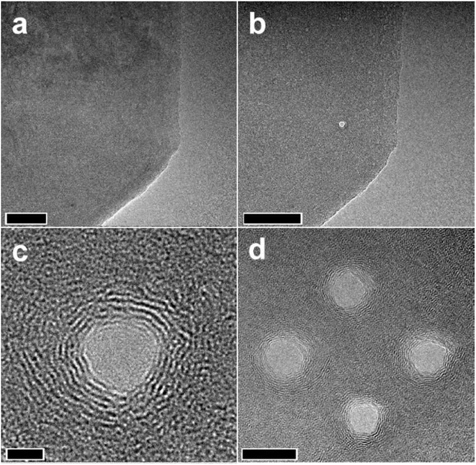 | ||
| Fig. 4 TEM images of a graphene sheet (a) before and (b) after an energetic electron beam makes a nanopore. (c) Higher magnification image of the nanopore. (d) Multiple nanopores are made close to each other. Scale bars are 50, 50, 2, and 10 nm, respectively. Reprinted and adapted with permission.48 Copyright 2008, AIP Publishing. | ||
A low energetic electron beam has also been shown to be an effective approach in creating pores on graphene sheets. In the work by Fox et al., <10 keV focused electron beam in an SEM system was used to create pores in the presence of nitrogen gas.50
The stability of the holes formed by energetic electrons was studied by Girit et al. using a TEM system.51 The study revealed the complex behavior of the carbon atoms at the edge. The edge reconfiguration process and hence the change in the shape of the hole and stability of the zigzag configuration over the armchair type were observed. Schneider et al. further demonstrated the use of such pores in DNA relocation.52
On the other hand, Russo et al. combined both ion and electron beam to create nanopores.53 Initially, 3 keV Ar ions were used at low temperature (148 K) to create defect nucleation centers on a single-layer graphene sheet. The sample was then warmed to room temperature (RT) and irradiated with an 80 keV electron beam to create pores in the nanometer scale.
Similar to the electron beam, a focused ion beam (FIB) can also be used to create pores on a graphene sheet. As compared to the case of the electron beam, an ion beam can be very effective in creating holes as ions are much heavier than electrons; thus, momentum transfer from the ions to the bonded carbon atoms is easier. Wang et al. showed the fabrication of nanometric holes on a single-layer graphene sheet using 30 kV Ga ion beam.54 The obtained pore size could be of few tens of nm and pores with an elliptical shape could be made as well. Similarly, Celebi et al. used FIB to create pores of the size 10 nm to 1 micron on double layer graphene.55 The pores could be used to study the transport phenomenon of liquid, gas, etc. Similar works were carried out by O'Hern et al. to create pores of size 0.40 ± 0.24 nm.56 The fabrication of tunable holes in the range of 1–4 nm diameter was demonstrated by Vazquez et al. using swift heavy ions.57 Swift heavy ions generally refer to the heavy mass with high energy (>MeV) particles and can be generated in a particle accelerator.58 Such energetic particles can produce tracks on their path in a material and when mono or few layers of graphene is used, holes can be formed.
In another study conducted by Nebogatikova et al., the formation of 20–60 nm size nanopores was demonstrated using Xe swift heavy ions.59 The sizes of the pores were found to be independent of the energy and dose of the ions, and the number of pores can be increased with the ion dose.
An interesting simulation study carried out by Li et al. on the fabrication of nanopores on graphene sheet by ion beam suggested the use of Au ions for creating perfect nanopores with smooth edges.60 The study also unveiled that the use of higher ion beam energy leads to lower damage. When carbon ions are used, it is indicated that with energy more than 5 keV, a complete nanopore cannot be formed; however, this relation vanishes when the incident ion beam mass increases.
Pore fabrication approaches using electron and ion beam are summarized in Table 2. Even though energetic electron and ion beams have been very effective in fabricating porous graphene sheets in a controllable and precise way, the technique has limitations in the fabrication of large-scale porous graphene sheets. Thus, this method is not a suitable approach for the mass scale synthesis of holey graphene material economically.
| Beam type | Energy regime | Beam energy (and ion type) | Mechanism/method | Pore size | Application | Ref. |
|---|---|---|---|---|---|---|
| Electron beam | Low energy (SEM) | <10 keV | Electron beam was focused on the graphene sheet in the presence of N2 gas. N2 was ionized, which then reacts with C atoms to form a gaseous product | <10 nm | — | Fox et al.50 |
| High energy (TEM) | 200 keV | Focused electron beam-induced ablation | 3.5 nm | — | Fischbein et al.48 | |
| 300 keV | Electron beam-induced knock out and temperature-assisted self-repair of the amorphized region | ∼(1–10) nm | — | Song et al.49 | ||
| Pores are created on a graphene sheet suspended on an SiN membrane | 2–40 nm | DNA translocation | Schneider et al.52 | |||
| 200 keV | Pores are created on the graphene sheet suspended on an SiNx membrane | Few nm (<10 nm) | DNA sequencing | Garaj et al.61 | ||
| 80 keV | 3 keV Ar ions were irradiated at low temperature to create defects, followed by electron beam irradiation at RT | 0.3 nm | — | Russo et al.53 | ||
| Ion beam | Low energy (FIB/ion sputtering system) | ∼keV Ga, He | Focused ion beam-induced drilling | <10 nm to 1 μm | Permeation membrane | Celebi et al.55 |
| 5–30 keV: Ga | Ion beam milling | <10 nm | — | Buchheim et al.62 | ||
| 10–30 keV: He | ||||||
| 8 keV: Ga | Ion beam etching | 0.40 ± 0.24 nm | — | O'Hern et al.56 | ||
| High energy (swift heavy ion) | MeV range: Xe, I, O, Si, C, Au | The SHIs created structural modifications with cylindrical symmetry (‘tracks’) along the ion path within the target material | 1–4 nm | — | Vazquez et al.57 | |
| 26–167 MeV: Xe | Energy transfer via the electronic stopping process (ionization loss) | 20–60 nm | — | Nebogatikova et al.59 |
2.2 Thermal: annealing method
It has been reported that upon heat treatment of GO or rGO, the process could result in the formation of HG.63–65 Structurally, both GO and rGO are similar as they are both derivatives of graphite or graphene and both have functional groups in the form of hydroxyl, oxygen, or carboxyl groups.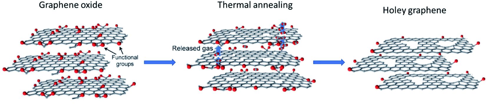 | ||
| Fig. 5 Schematic representation of the formation of holey graphene from graphene oxide using rapid thermal annealing. Reprinted and adapted with permission.66 Copyright 2015, John Wiley and Sons. | ||
A similar low-cost and simple method based on rapid thermal annealing was demonstrated by Peng et al.63 In their work, GO powder was taken as the starting material and rapidly annealed at a temperature as low as 300 °C. Initially, the quartz tube furnace was heated to 300 °C and kept for 30 min. Thereafter, a long-handled stainless-steel lab spoon containing the GO powder was inserted. The estimated heating rate was 100 °C s−1 or 6000 °C min−1. Holes with sizes in the range of 10–250 nm were created. The number of holes was controlled with the ramping rate of temperature increase. The grown HG nanosheets have shown promising results in supercapacitor applications. The specific capacitance at all the current densities was found to increase with the number of holes as created by raising the heating rate. The supercapacitor made with the holey graphene nanosheets showed a specific capacitance of 211 F g−1 at 0.5 A g−1, which was 49% higher than that of the supercapacitor made with the non-holey counterpart.
Wu et al. considered a similar approach to gain a higher ramping rate for the RTA process.64 First, a tube furnace filled with Ar atmosphere was preheated to 1100 °C and kept there. In the next step, a long metal tool was used to place the GO powder in the central region of the furnace. This allows a high ramping rate of 18000 °C min−1. This ultra-high ramping rate produces a large amount of CO2 gas in between the neighboring layers in a short span of time. It leads to the generation of huge pressure. This results in the piercing of the graphene sheets at their weak spots thus forming holes. HG was synthesized in this way and subsequently applied in lithium-ion battery (LIB).
Xing et al. used anthracite (raw coal) and graphitized it using a high temperature furnace.67 Later, Hummers' method was utilized to obtain coal-based GO (CGO) from the graphitized sample. The CGO sample was then placed in a crucible and heated rapidly at 900 °C for 10 min in N2 flow to generate pores in the sample. Corrugated nanosheets with micro–meso–macroporous structure were obtained for LIB application as an anode material. Table 3 summarizes the different rapid thermal annealing treatments reported in the literature and the obtained pore sizes.
| Annealing type | Starting material | Temp. (°C); time | Gas atmosphere | Ramping rate | Final material | Pore size (nm) | SSA (m2 g−1) | Application | Ref. |
|---|---|---|---|---|---|---|---|---|---|
| Rapid | GO powder | 300 | Air | 100 °C s−1 | HGNS | 10–250 | 592 | Supercapacitor | Peng et al.63 |
| GO | 300 | — | > 100 °C s−1 | HGNS | 50–100 | 750 | Supercapacitor | Yang et al.66 | |
| 1000 | — | 800 | |||||||
| GO | 1100, 1 h | Ar | 18000 °C min−1 |
HG | 5–500 | 779 | LIB | Wu et al.64 | |
| GO | 400 °C, 10–60 min, 900 °C, 2 h | Air | — | HG | — | 733.5 (10 min–900) | — | Zhou et al.68 | |
| Coal–GO (anthracite) | 900, 10 min | Nitrogen | — | Porous graphene | Micro–meso–macro | 640 | LIB | Xing et al.67 | |
| GO | 300 | Ar | >100 °C s−1 | HGNS | 50–300 | 750 | NaIB | Luo et al.69 | |
| 1100 | 800 | ||||||||
| GO powder | 1100, 1 h | Ar | 18000 °C min−1 |
HG | 5–300 | 780 | LIB | Huang et al.70 |
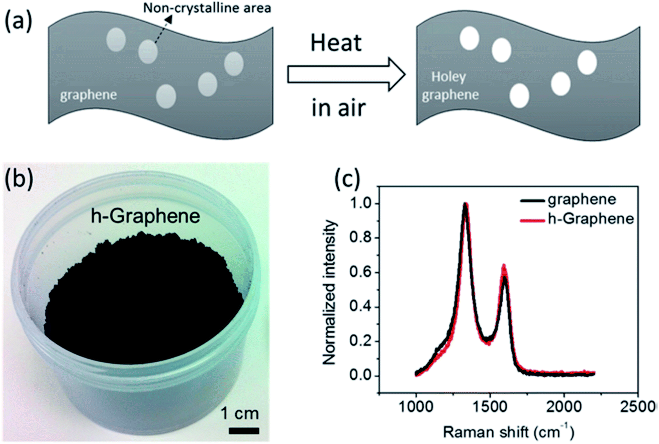 | ||
| Fig. 6 (a) Schematic of holey graphene synthesis from graphene sheets, (b) as-synthesized holey graphene powder in bulk, and (c) Raman spectra obtained from holey graphene and the starting graphene material. Reprinted with permission.71 Copyright 2014, American Chemical Society. | ||
Following the same approach, Xu et al. synthesized HG from graphene material, after which N-doped HG was prepared by annealing graphene and HG at 500 °C for 5 h in a tube furnace in the presence of NH3/Ar gas glow.74 The doped HG was demonstrated to be an effective anode material for LIB.
A nanomanufacturing method was introduced by Chen et al. through the thermal annealing of commercially available few-layer graphene powder.75 The powder was placed in a quartz boat and heated to ∼710 K with a 10 K min−1 heating rate and kept in an open-ended tube furnace for 10 h. The process gives HG powder with an average pore size of 15 nm. The prepared holes could be repaired and closed if treated at a high temperature (2700 K).
Su et al. demonstrated a facile method to prepare HG nanoscrolls from GO nanosheets.65 Schematically, the process is shown in Fig. 7. As the first step, large-size GO sheets were cold quenched in liquid nitrogen to synthesize the GO nanosheets. After that, GONSs were thermally annealed at 500 °C for 1 h in an NH3 environment to synthesize nitrogen-doped graphene nanosheets (NGNSs). The NGNSs were further annealed in air with an open-ended tube furnace at 360 °C for 5 h to obtain nitrogen-doped holey graphene nanosheets (NHGNSs). The NGNSs materials demonstrate promising results as electrode materials for supercapacitors and other electrochemical energy storage devices.
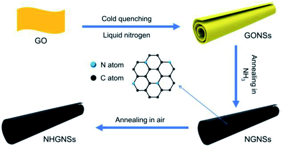 | ||
| Fig. 7 Schematic picture showing the steps to prepare HG nanoscrolls, as demonstrated by Su et al. Reprinted with permission.65 Copyright 2021, Elsevier. | ||
Xing et al. synthesized HG nanosheets (HGNSs) from oxidized graphite powder using a low temperature (300 °C) thermal treatment method.12 Oxidized graphite powder was prepared using the modified brodie method and the prepared powder was put in a glass beaker to start the annealing process in air for 30 min. A high specific surface area (SSA) of 1053.3 m2 g−1 was obtained, which exhibits excellent properties in the absorption of oils, solvents, and dyes.
Xiao et al. described a low-cost, large-scale production method of HG from commercially available graphite powder.76 The powder was placed in an alumina crucible and placed inside a furnace. The furnace was gradually heated up to the temperature range of 800–1100 °C and kept there for 1 h under the flow of the Ar/H2O gas mixture. H2O steam acts as a mild oxidative reagent in the process. Well-defined hexagonal hole structures of few microns in size and mesopores were obtained. The material was tested as the anode in LIB and showed promising results.
Table 4 summarizes the works of the GTA method. Holey/porous graphene synthesis via RTA process has been found to be faster for HG fabrication than the GTA process, which usually takes time. Nevertheless, both types of annealing processes can synthesize HG materials, which showed promising results in energy storage applications.
| Annealing type | Starting material | Temp. (°C); time | Gas atmosphere | Ramping rate | Final material | Pore size (nm, avg.) | SSA (m2 g−1) | Application | Ref. |
|---|---|---|---|---|---|---|---|---|---|
| Normal/GTA | Graphene powder | ∼436.85 °C (710 K); 10 h | Air | 10 K min−1 | HG powder | 15 | — | — | Chen et al.75 |
| Graphene powder | <500 (430–480); 3 h, 10 h | Air | ∼10 °C min−1 | HG | <10 | 658 (480 °C/10 h) | Ultracapacitor | Han et al.71 | |
| Graphene powder | 430, 10 h | Air | ∼10°C min−1 | HG | — | — | Li–CO2 battery (HG-quantum dot composite) | Jin et al.72 | |
| Graphene powder | 430, 10 h | Air | 10 °C min−1 | HG | 5–15 | ∼600–700 | Supercapacitor | Walsh et al.11 | |
| Graphene | 430; 3 h | Air | ∼10 °C min−1 | HG | — | 398.9 | LIB | Xu et al.74 | |
| Gr and HG | 500; 5 h | NH3/Ar | — | N-Doped HG | — | 594.6 | |||
| GO | 360; 5 h | Air | 5 °C min−1 | NHGNs | — | — | Supercapacitor | Su et al.65 | |
| Oxidized graphite powder | 300, 30 min | Air | — | HGNSs | 1.4–16.3 | 1053.3 | Water cleaning | Xing et al.12 | |
| Graphite | 800–1100, 1 h | Ar/H2O | — | HG | ∼5 nm (mesopore)–2 μm (micro) | 4.4 (1000 °C) | LIB | Xiao et al.76 |
2.3 Chemical: nanoparticle-assisted oxidation (catalytic oxidation)
In the work carried out by Lin et al., a simple chemical process based on the catalytic property of silver (Ag) was utilized to create holes on graphene sheets.77 Initially, Ag nanoparticles were deposited on the graphene sheets, and then the Ag coated samples were thermally annealed in air. The carbon atoms in contact with the Ag nanoparticles are oxidized and CO or CO2 are formed. The process results in the formation of holes with a size that can be controlled by controlling the size of the Ag nanoparticles that are being used. The steps are shown in the schematic presented in Fig. 8. After the oxidation process, the Ag nanoparticles can be removed using nitric acid, followed by extensive washing with water and subsequent drying. The electron microscopy images of a prepared holey graphene sample utilizing this approach are shown in Fig. 9. The dark spots (SEM image: Fig. 9a) and the bright ones (TEM image: Fig. 9b) correspond to the holes formed during the process.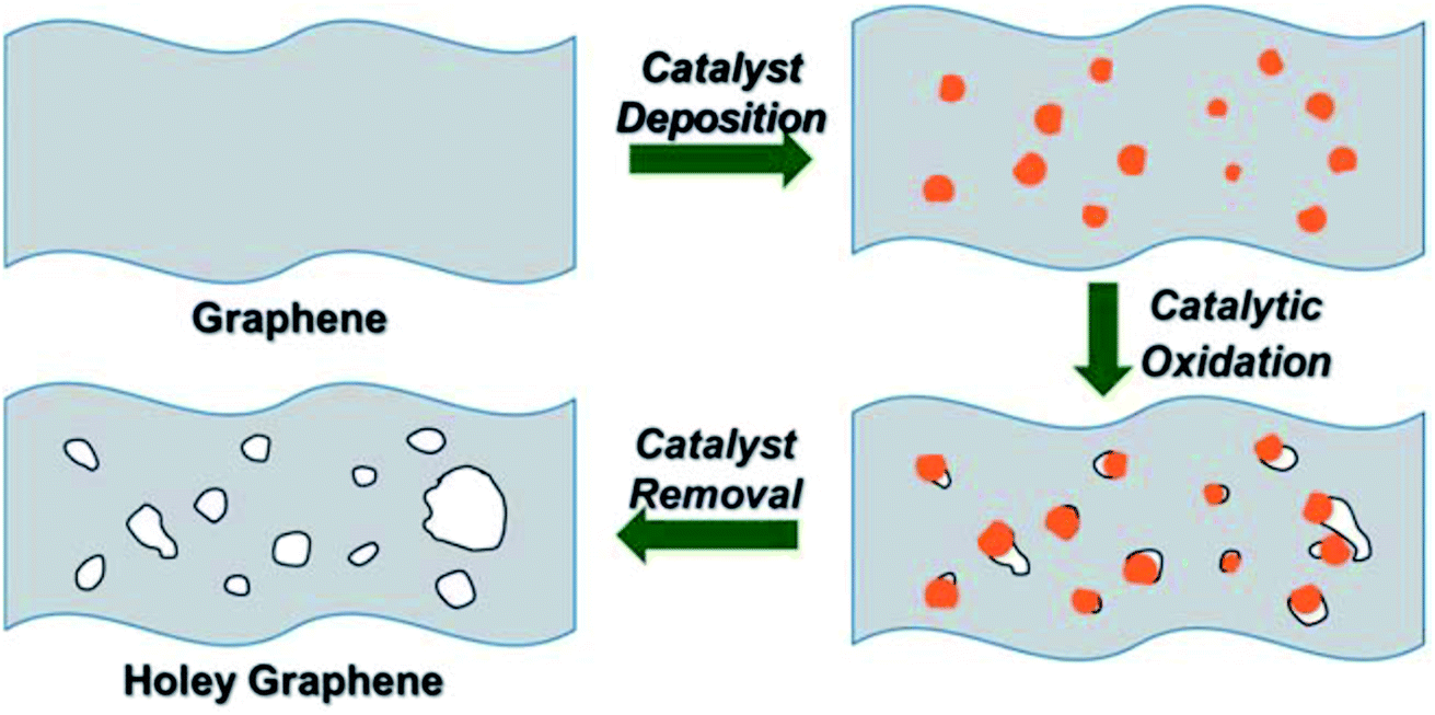 | ||
| Fig. 8 The 3-step process to prepare holey graphene (HG) using Ag nanoparticles as discussed by Lin et al. Reprinted with permission.77 Copyright 2013, Royal Society of Chemistry. | ||
 | ||
| Fig. 9 Electron microscopy images of a holey graphene sample prepared using Ag nanoparticles as the catalyst. Reprinted with permission.77 Copyright 2013, Royal Society of Chemistry. | ||
Alsharaeh et al. presented a different approach to obtain Ag-decorated GO using microwave heating.78 Initially, GO was mixed with AgNO3, then sonicated and stirred. Thereafter, the solution was put inside a conventional microwave to obtain Ag-decorated rGO sheets. The Ag-rGO sample was then kept in a furnace at 300 °C for 2 h. Subsequently, the sample was refluxed with dilute nitric acid and microwave treated to remove the Ag particles. After washing in water and drying, HrGO was obtained. The obtained material was used as an anode in LIB.
A chemical patterning method was proposed by Seo et al. using FeIII porphyrin covalent organic framework (COF) as a surface catalyst and template.79 HOPG material was taken as a starting material for catalytic oxidation. The oxidation process was carried out with H2O2 and NaOCl. Using this method, regular holes were created on the HOPG sample.
In a recent work performed by Wang et al., ZnO nanoparticles were used with GO to create holes on the GO sheets.80 A solution was prepared with GO and ZnO to prepare a layer-by-layer pattern of GO–ZnO, as schematically shown in Fig. 10. This composite material was then calcined at a high temperature. During the calcination process, graphene was formed and the ZnO nanoparticles etch the adjacent graphene sheets, thus creating holes. Zn metal is produced as a side product, which could be removed by heating the material at 900 °C.
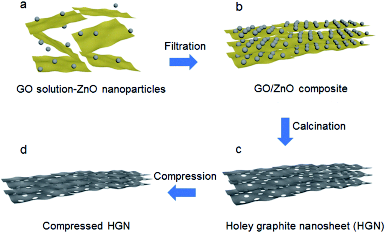 | ||
| Fig. 10 The synthesis approach to produce holey graphene sheets from GO using ZnO nanoparticles. Reprinted with permission.80 Copyright 2018, Royal Society of Chemistry. | ||
A similar approach was implemented by Du et al.81 In their work, Fe2O3 nanoparticles were formed on graphene sheets by implementing a simple hydrothermal reaction between FeCl3 and GO. On further annealing, the Fe2O3 nanoparticles can etch the surrounding graphene sheets and create holes in this way. The material was used in Li ion storage.
A Cu nanoparticle-assisted oxidation method was described by Dutta et al.82 Initially, a Cu–graphene solution was prepared by mixing the Cu2+ salt with the graphene material. The mixture was then annealed in two ways. First, rapid thermal annealing (RTA) in H2 environment for 15 min and then gradual thermal annealing (GTA) at 900 °C for 15 min (with H2 upon onset and until the end at 900 °C) was done. It was found that Cu could be utilized as a catalyst for the reaction of sp2 carbon with H2 to produce CH4, as shown in the equation below.
Following the annealing process, Cu nanoparticles can be removed using dilute nitric acid. The prepared Cu–graphene mixture with densely decorated Cu NPs is shown in Fig. 11a. Cu NPs have a mean particle size of 23.5 nm. Fig. 11b shows the HG sample after Cu NPs removal and the inset indicates a high degree of crystallinity of HG. Fig. 11c is a high-resolution bright field TEM image of a uniform HG (u-HG) obtained by RTA at 900 °C. It has a mean pore size of 24.2 nm, which can be correlated to the mean Cu NP size of 23.5 nm. The hierarchical presence of micro-, meso-, and macroscale pores in the few layers of graphene was observed. The TEM image in Fig. 11d shows a range of hierarchical pores observed at different layers stacked one above the other. The tailoring of HG with optimized porosity results in high areal capacitance and excellent cycling stability, indicating that HG is a promising material for energy storage applications.
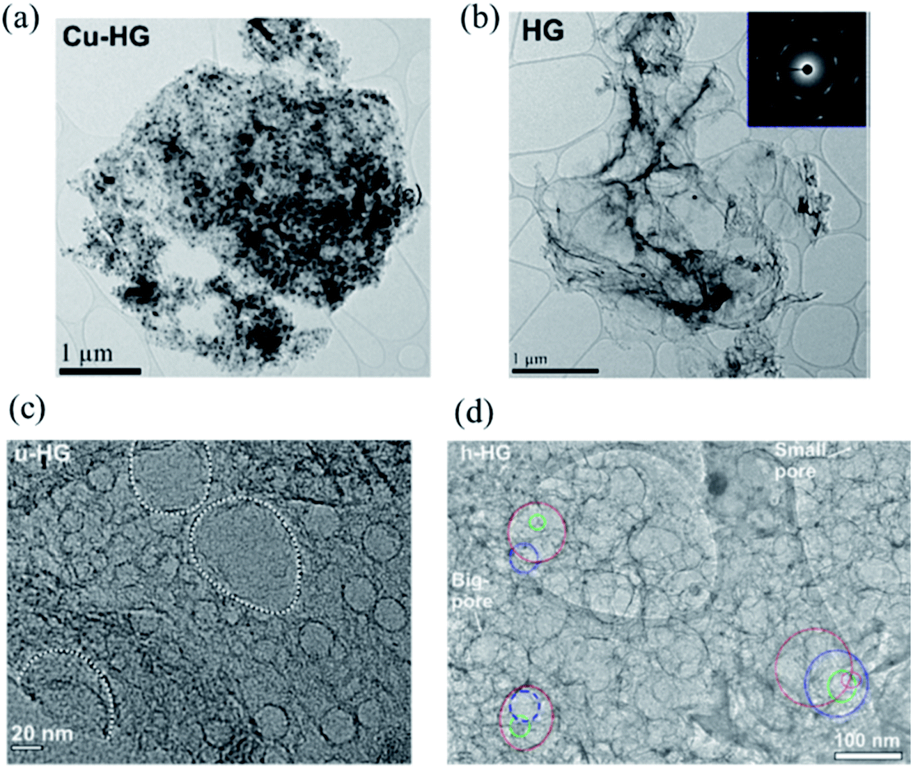 | ||
| Fig. 11 (a) TEM image of the Cu–graphene composite. (b) TEM image of the graphene sheet after the removal of the Cu nanoparticles; selected area electron diffraction (SAED) pattern of HG is shown in the inset. (c) Higher-magnification TEM image of uniform HG (u-HG) showing a monodispersed distribution of pores and (d) the TEM image of hierarchical h-HG (pores on different layers of the h-HG; red, top layer; blue, 2nd layer; green, 3rd layer; magenta, 4th layer). Reprinted and adapted with permission.82 Copyright 2019, American Chemical Society. | ||
Table 5 summarizes the use of different types of nanoparticles for the synthesis of HG. Nanoparticle-assisted oxidation and pore creation are exciting approaches due to the porosity tailoring capability of the method through the nanoparticle size distribution. However, the technique may not be a suitable approach for the mass-scale production of HG.
| Nano particle | Starting material | Pre-treatment | Synthesis process | Gas atmosphere | Temp. (°C); time | Final material | Pore size (nm) | SSA (m2 g−1) | Application | Ref. |
|---|---|---|---|---|---|---|---|---|---|---|
| Ag | Graphene | — | Ag nanoparticles were deposited on the graphene sheets, and then the Ag-coated samples were thermally annealed in air. | Air | 300 | HG | ∼5 to tens of nm | 590 | — | Lin et al.77 |
| GO | GO mixed with AgNO3, heat and microwave treatment | Ag-rGO was heat treated, refluxed with nitric acid, and microwave treated. | Ar | 300; 2 h | HRGO | 2–5 | 457 | LIB | Alsharaeh et al.78 | |
| FeIII porphyrin | HOPG | — | Metalated COF was grown on graphite, oxidized (H2O2/NaOCl), and COF was removed | — | — | HG | 4–50 | — | — | Seo et al.79 |
| ZnO | GO | — | Layer by layer motif of GO-ZnO was prepared, filtered, and calcined. | Nitrogen | 900; 4 h | HG nanosheet | <10 | 484 | Supercapacitor | Wang et al.80 |
| Fe2O3 | Graphene | Hydrothermal reaction (180 °C for 12 h) | Calcined in a tube and etched with HCL solution | Argon | 850; 2 h | Graphene mesh with pores | 60–200 | 381 | LIB | Du et al.81 |
| Cu | Graphene | Copper oxide-graphene composite is obtained by the hydrothermal method | The solution was annealed and dilute nitric acid was used to remove the Cu particles | Hydrogen | 900; 15 min | HG | Meso: 2.5, 7.6, 11.2, 27.2, 34.7; macro: 52.9; micro: <2 | 107.8 | Supercapacitor | Dutta et al.82 |
2.4 Chemical: chemical etching method
HG can be obtained from GO by means of wet chemical methods as well. Zhao et al. prepared a mixed solution of GO and HNO3.83 The solution was then sonicated for 1 h. Sonication helps HNO3 to react with the unsaturated carbon atoms at the damage sites and the edge sites of GO. The process results in the removal of carbon atoms from the GO sheet and accordingly, the formation of nanopores. Pores in the size range of 7–600 nm could be obtained in different holey GO (HGO) samples. Reduced HGO was prepared after thermally reducing the porous samples (Fig. 12) and paper electrodes were prepared, which exhibited enhanced Li-ion storage capacity and transport properties.83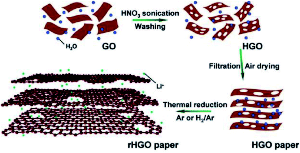 | ||
| Fig. 12 Synthesis of HGO and rHGO from GO using HNO3. Reprinted with permission.83 Copyright 2011, American Chemical Society. | ||
A nanomesh of graphene (GNM) was prepared by Wang et al. by refluxing rGO sheets in concentrated HNO3 solution for 4, 6, 9, or 11 hours.84 The porous structures of GNMs could be controlled with the reaction time and the size of the nanopores could be modulated from a few to hundreds of nanometers. The use of HNO3 was also reported in another study by Chang et al. who prepared graphene electrodes using self-assembled 3D graphene made of graphene flakes with nanopores (∼2.5 nm) for high-performance supercapacitor application.85 A three-step approach was implemented, as shown in Fig. 13, to obtain a 3D assembly of micro/nanoporous GO. First, the GO solution was mixed with HNO3. HNO3 then reacts with the defect sites on the edges of GO. The process results in the removal of carbon atoms from the GO flakes and holey GO is formed. In the next step, freeze-drying was used to obtain the 3D graphene monolith and lastly, thermal reduction was carried out to get 3D porous graphene.
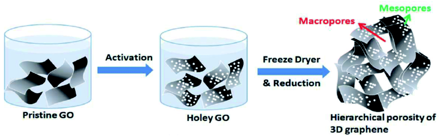 | ||
| Fig. 13 A three-step approach to obtain porous 3D graphene as demonstrated by Chang et al. Reprinted with permission.85 Copyright 2016, Royal Society of Chemistry. | ||
Similarly, Chowdhury et al. prepared HGO by sonicating a mixture of aqueous GO dispersed solution and HNO3.86 The as-prepared HGO was then annealed under N2 gas at 500 °C for 30 min to obtain a holey graphene framework. The synthesized HG material was used in post-combustion CO2 adsorption systems for carbon capture application. Table 6 presents the synthesis parameters adopted by different groups using HNO3.
| Etchant | Starting material | Pre-treatment | Synthesis process | Temp. (°C) | Final material | Pore size (nm) | SSA (m2 g−1) | Application | Ref. |
|---|---|---|---|---|---|---|---|---|---|
| HNO3 | GO | Mixed solution of HNO3 and GO is sonicated at RT for 1 h | HNO3 reacts with the unsaturated carbon atoms at the damage and edge sites of GO | RT | Holey GO | 7–600 | 15 | Energy storage | Zhao et al.83 |
| rGO | — | 50 mL rGO dispersion (0.1 mg mL−1) mixed with HNO3 solution and then refluxed for 4–11 h | 100 | Graphene nanomesh | 0–100 | 1010 ± 60 | — | Wang et al.84 | |
| GO | Mixed solution of GO and HNO3 (70%) are sonicated for 1 h | Freeze dried and thermally reduced. | — | 3D porous graphene | Micropore ∼20 μm; nanopore ∼2.5 nm | 564 | Supercapacitor | Chang et al.85 | |
| GO | — | Mixed solution of HNO3 and GO was sonicated | — | Holey GO | 3–4 | 524 | Carbon capture | Chowdhury et al.86 |
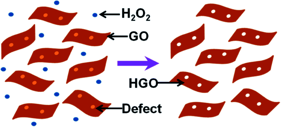
Xu et al. used H2O2 as an etching agent and mixed it with GO. The solution was then heated at 100 °C for 4 h under stirring to obtain holy-GO.87 The residual H2O2 was later removed by centrifugation and washing of the reaction mixture. The process is shown schematically in Fig. 14. During the heating process, the defective carbon atoms were oxidized and subsequently etched. As a result, pores are formed. The pore size distribution on the basal plane in the range of 2–3 nm was obtained. Superior capacitive energy storage properties were observed, which were due to the presence of hierarchical 3D porosity in the material.87 Similarly, the group also produced holey graphene framework (HGF) for electrochemical energy storage applications.88
 | ||
| Fig. 14 A schematic diagram to describe the synthesis process of HGO. Reprinted with permission.87 Copyright 2015, American Chemical Society. | ||
Using a similar process, nanohole GO (NHGO) was synthesized from a homogeneous aqueous mixture of GO and H2O2.89 The mixture was sonicated for 30 min to prepare the homogeneous solution. The solution was then kept inside an autoclave and hydrothermally treated at 120 °C for 10 h. NHGO with pore size in the range of 2–3 nm was obtained. Other groups carried out similar studies to obtain the porous form of the graphene derivative.90
The oxidation process assisted by H2O2 was also reported to create porous graphene from graphene.91 The oxidation of graphene was initiated by H2O2 and the process could also yield graphene quantum dots. In a separate study, the composite of GO–TiO2 was prepared by Xu et al. using sonication and further heat treated in H2O2 solution to prepare the HG–TiO2 material for photocatalytic applications.92
Wang et al. used a microwave reactor to produce HGO.93 Initially, GO aqueous solution was prepared from graphite flakes using an improved Hummers' method.94 The GO solution was then mixed with H2O2, kept in a reaction tube, and irradiated in a microwave reactor at a constant power of 50 W for 45–180 s. The solution was cooled and residual H2O2 was removed via centrifugation. The precipitate was re-dispersed in deionized water to form HGO. HGO was further microwave irradiated at 220 °C for 90 s to synthesize rHGO. The size of the holes could be controlled with the microwave irradiation time. The rapid synthesis process could be attributed to the in situ heat generation process in the sample (GO sheets) during the microwave irradiation. The increased surface area and ion diffusion in the HGO boosts the electrochemical catalytic activity and displays excellent capacitive performance.93 HG synthesis using H2O2 etching agent by different groups is summarized in Table 7.
| Etchant | Starting material | Pre-treatment | Synthesis process | Temp. (°C); time | Final material | Pore size (nm) | SSA (m2 g−1) | Application | Ref. |
|---|---|---|---|---|---|---|---|---|---|
| H2O2 | GO | 40 mL GO suspension was mixed with 0.4 mL H2O2 and sonicated for 30 min | Hydrothermally treated at 120 °C for 10 h in an autoclave | 120 | HGO | 2–3 | 425 | Supercapacitor | Jinlong et al.89 |
| GO | — | Aqueous mixture is stirred for 4 h | 100 | HGO | 2–3 | 1330 | Supercapacitor | Xu et al.87 | |
| Gr | 100 mg of graphene was dispersed (sonicated) in 100 mL of H2O2 (30%) for 10 min | The reaction mixture's temperature was increased to 70 °C and kept for 72 h. | 70 | pGr, GQD | 0.7–9 | 204 | Electrocatalyst (oxygen reduction) | Palaniselvam et al.91 | |
| GO | GO suspension (20 mL, 2 mg mL−1) mixed with H2O2 | The solution was cured in an autoclave for 6 h | 180 | Holy graphene hydrogel (HGH) | 3D hierarchical porous structure (tens of nm – a few micron) | 1261.7 | Water desalination | Kong et al.90 | |
| GO | — | Mixed solution was stirred at 100 °C for 1, 2, 4, and 4.5 h | 100 | HGO | 34 ± 7 to 62 ± 19 | — | Water desalination | Chen et al.38 | |
| GO | GO solution was prepared from graphite flakes | Mixed solution of GO and H2O2 was irradiated in a microwave reactor | 45–180 s | HGO | 13.4 (avg) | — | — | Wang et al.93 | |
| The HGO was further microwave irradiated | 220, 90 s | rHGO | — | ||||||
| GO | GO dispersion was added in TiO2 suspension | H2O2 solution was added with GO–TiO2 and heated | 160, 4 h | HG–TiO2 hybrid | — | — | Photocatalysis | Xu et al.92 |
Similar to H2O2, various groups used KOH as an activation agent to create porous graphene/GO material. KOH could react with carbon according to the thermodynamically possible reaction shown below.95
| 6KOH + 2C ↔ 2K + 2K2CO3 + 3H2 |
The as-produced K and K2CO3 can further react with carbon and create pores. The activation process can generate a continuous 3D network of pores in the range of 1–10 nm.96 It was found that highly graphitic carbons are not suitable for the KOH activation process. However, the oxygen-functional groups (such as C![[double bond, length as m-dash]](https://www.rsc.org/images/entities/char_e001.gif) O and COOH) attached on the surface can play a crucial role in porosity development. These surface functional species can react with KOH to form an intermediate product of the C–O–K species. This can further react with the carbon of the precursor material to give a material with a porous structure.97
O and COOH) attached on the surface can play a crucial role in porosity development. These surface functional species can react with KOH to form an intermediate product of the C–O–K species. This can further react with the carbon of the precursor material to give a material with a porous structure.97
Similarly, Xu et al. prepared HG from graphene powder using KOH.98 In this process, graphene powder was mixed with KOH powder and heated at 800 °C for 1 h in Ar environment to activate the chemical reaction. The experiment resulted in the formation of graphene powder with pores in the range of 1–5 nm. Xia et al. prepared 2D porous graphene from exfoliated GO (EGO).99 The EGO samples were obtained by the thermal treatment of dried GO at 800 °C. The EGO material was then activated using KOH at 800 °C for 1 h under N2 flow. The research group also implemented CO2 to obtain porous graphene from the EGO samples. The CO2-activated graphene was reported to have a 3D curly morphology with hierarchical micro–meso–macroscopic structure.
Zheng et al. prepared rGO by reducing GO powders prepared by modified Brodie's method.100 Later, porous activated graphene was synthesized by mixing rGO with KOH at a weight ratio of 1:8 and kept at 850 °C for 2 h in Ar atmosphere. The sample was then cleaned with HCl solution, followed by DI water, and then dried to get the activated graphene (porous) sample. It was found that the crystallinity and oxygen functional groups play a crucial role in the growth of the porosity in the activated graphene.
Baburin et al. produced perforated graphene from rGO using methanol KOH solution for hydrogen storage application.101 In an exciting study carried out by Wu et al., a 3D heterostructure architecture combined with holey graphene sheets intercalated with the carbon sphere was fabricated (shown in Fig. 15).102 rGO and carbon spheres were separately synthesized and mixed through a self-assembly process. Later, the solution was activated at 800 °C for 1 h in Ar atmosphere to create pores on the graphene layers. Due to the unique pillar structure, improved electrical conductivity, higher ionic movement, and diffusion were observed; as a result, the paper electrode made of the synthesized material showed high energy density and excellent cycling stability for energy storage devices.
 | ||
| Fig. 15 Schematic picture showing the formation of carbon sphere intercalated holey graphene sheets in a 3D heterostructure architecture form. Reprinted with permission.102 Copyright 2017, Elsevier. | ||
Jiang et al. used a combined process of chemical etching using KOH and ball milling to produce randomly stacked HG (RSHG).103 Initially, GO (synthesized using modified Hummers' method) was dispersed in DI water and ultrasonicated for 1 h. The solution was then placed in an autoclave and heated to 180 °C for 12 h to produce the graphene hydrogel. The graphene hydrogel was mixed with KOH and stirred (etched) for 12 h and then ball milled for 30 h. The material was then washed with HCl solution and DI water, and then the RSHG was obtained. The prepared RSHG was demonstrated as a potential anode material for LIB. Pore generation and synthesis of HG using KOH are summarized in Table 8.
| Etchant | Starting material | Pre-treatment | Synthesis process | Temp. (°C) | Final material | Pore size (nm) | SSA (m2 g−1) | Application | Ref. |
|---|---|---|---|---|---|---|---|---|---|
| KOH | GO | Microwave exfoliated GO (MEGO) and thermally exfoliated GO are prepared | MEGO was chemically activated by mixing with KOH | — | Activated MEGO | 1–10 | 3100 | Supercapacitor | Zhu et al.96 |
| Graphite oxide | Graphene powder was produced from graphite oxide by a vacuum-promoted low-temp. Exfoliation | The graphene powder was mixed with KOH and heated for 1 h under Ar atmosphere | 800 | HG powder | 1–5 | 2300 | Conductive additive in the LiFePO4 cathode | Xu et al.98 | |
| GO | Exfoliated GO is prepared from GO using thermal treatment | Activation was done at 800 °C for 1 h under N2 flow | 800 | HG (2D lamellas) | Bimodal micro–mesopore | 2518 | Supercapacitor | Xia et al.99 | |
| rGO | GO powders were reduced at 600 °C for 30 s in Ar atmosphere | rGO mixed with KOH (1:8) and chemically activated at 850 °C for 2 h in Ar atmosphere, cleaned, and dried |
850 | Porous activated graphene | — | 2406 | Supercapacitor | Zheng et al.100 | |
| rGO | Thermal exfoliation of GO is done to get rGO | rGO powder mixed with methanol KOH solution, dried and annealed at 800 °C for 1 h | 800 | Perforated graphene | ∼1.7 | 2900 | Hydrogen storage | Baburin et al.101 | |
| rGO, carbon sphere | rGO and carbon sphere (CS) are prepared separately | rGO and CS are mixed through a self-assembly process and activated using KOH for 1 h | 800 | HG intercalated with CS | 2–10 | 288.19 | Electrochemical capacitor | Wu et al.102 | |
| GO | Graphene hydrogel was produced by mixing GO and DI water and heating | The graphene hydrogel was mixed with KOH, stirred, and ball milled | — | Randomly stacked HG | — | 800 | LIB | Jiang et al.103 |
2.5 Chemical: template-assisted patterning
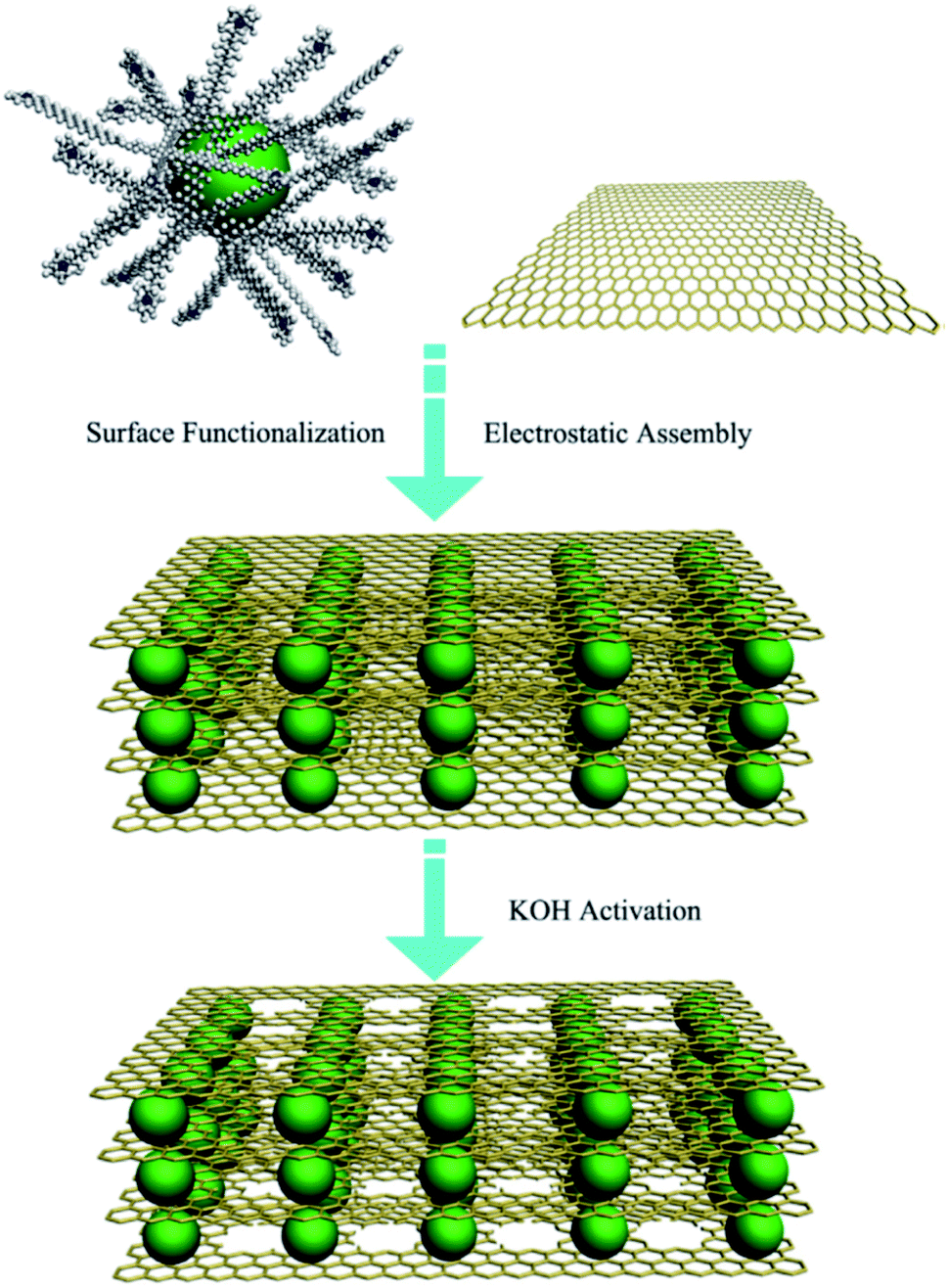
Periodic holes can be formed on graphene or GO sheets by patterning periodically on the sheets. For example, Zhang et al. proposed a method to synthesize nitrogen-doped HG nanocapsules (NHGNs) from GO nanosheets using a template etching process.104 Amino-functionalized SiO2 and GO were first assembled using electrostatic interactions (Fig. 16). The process resulted in the formation of GO-encapsulated SiO2 nanospheres (NSs). The material was then activated in the atmosphere of NH3/Ar gas at 900 °C for 90 min (heating rate 10 °C min−1). Subsequently, the obtained material was washed in HF aqueous solution and freeze-dried to get NHGNs.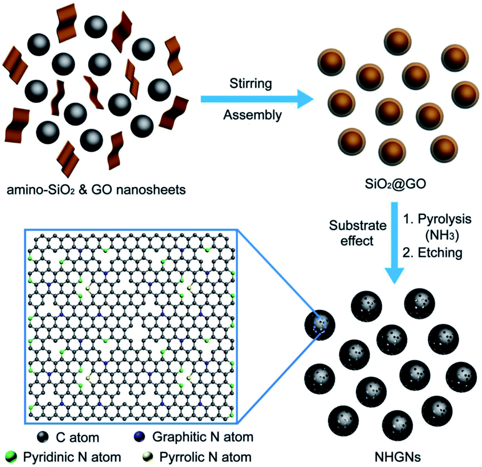 | ||
| Fig. 16 Schematic figure showing the steps for the synthesis of NHGNs. Reprinted with permission.104 Copyright 2016, John Wiley and Sons. | ||
Ning et al. employed a template chemical vapor deposition (CVD) synthesis method to obtain nanomesh graphene (NMG) having nanopores of the size of <10 nm.105,106 Boiling treatment was first applied to the MgO nanoparticles (20–100 nm) to obtain the Mg(OH)2 layers. These intermediate layers decompose to give porous MgO layers as a result of water release during calcination. In the next step, methane cracking (CVD) was carried out at 900 °C on porous MgO that finally gives the NMG. This NMG shows extraordinary ferromagnetic properties, which is believed to be due to the high-density defects present in the material.106 The NMG produced in this way was found to give excellent electrochemical capacitance, rate performance, and cycle stability.105 The high supercapacitor performance was attributed to the porous nature of the material and the high surface area.
Sinitskii et al. demonstrated a way to create graphene nanomesh by implementing Reactive Ion Etching (RIE) process.107 As indicated in the schematic Fig. 17, graphene was deposited on copper foils and transferred to an SiO2/Si substrate. (a) SiO2 (10 nm, Mask 1) was deposited and colloidal spheres were prepared using the self-assembly process. (b) RIE 1 (CF4) was then used to create gaps of ∼10 nm. (c) Au (10 nm, mask 2) was deposited and the colloidal spheres were removed by ultrasonicating in water. (d) RIE 2 (CF4 + O2) was subsequently used to etch away the exposed graphene regions. (e) Later, mask 1 and mask 2 could be removed by etching in dilute HF. (f) The size of the gaps and the neck widths could be controlled by the RIE parameters.
 | ||
| Fig. 17 Schematic of the nanomesh fabrication process using colloidal microspheres and RIE. Reprinted with permission.107 Copyright 2010, American Chemical Society. | ||
A similar approach was employed by Wang et al. to create graphene nanomesh.108 Initially, the SiO2 film was grown on the Cu foil, followed by the formation of polystyrene (PS) nanospheres through a self-assembly process on top of the SiO2 film. O2 plasma was used to etch and form gaps in between the closely packed nanospheres. Further, CF4 plasma was used to remove the exposed SiO2 regions around the nanospheres. The nanospheres were then dissolved with toluene and removed from the sample. Later, a low-pressure CVD process was used to grow graphene on the exposed Cu foil regions and graphene film with circular pores could be obtained in this way.
Shi et al. used spherical porous layered double hydroxide (LDH) and conformally calcined it to get layered double oxide (LDO) microspheres.109 These LDO microspheres were then used as a template to grow graphene using a high-temperature CVD process, as indicated in the schematic Fig. 18. Later, after a facile chemical etching process, purified graphene micromesh with hierarchical pores was obtained. Brunauer–Emmett–Teller (BET) experiments show a high surface area of 1275 m2 g−1. Hierarchical porous CaO particles were also used as a template to grow hierarchical porous graphene by the research group in a similar fashion.110 Both the graphene microspheres and the hierarchical porous graphene material were proposed as favorable scaffolds for rechargeable lithium–sulfur battery. Different template-assisted synthesis methods of HG are summarized in Table 9.
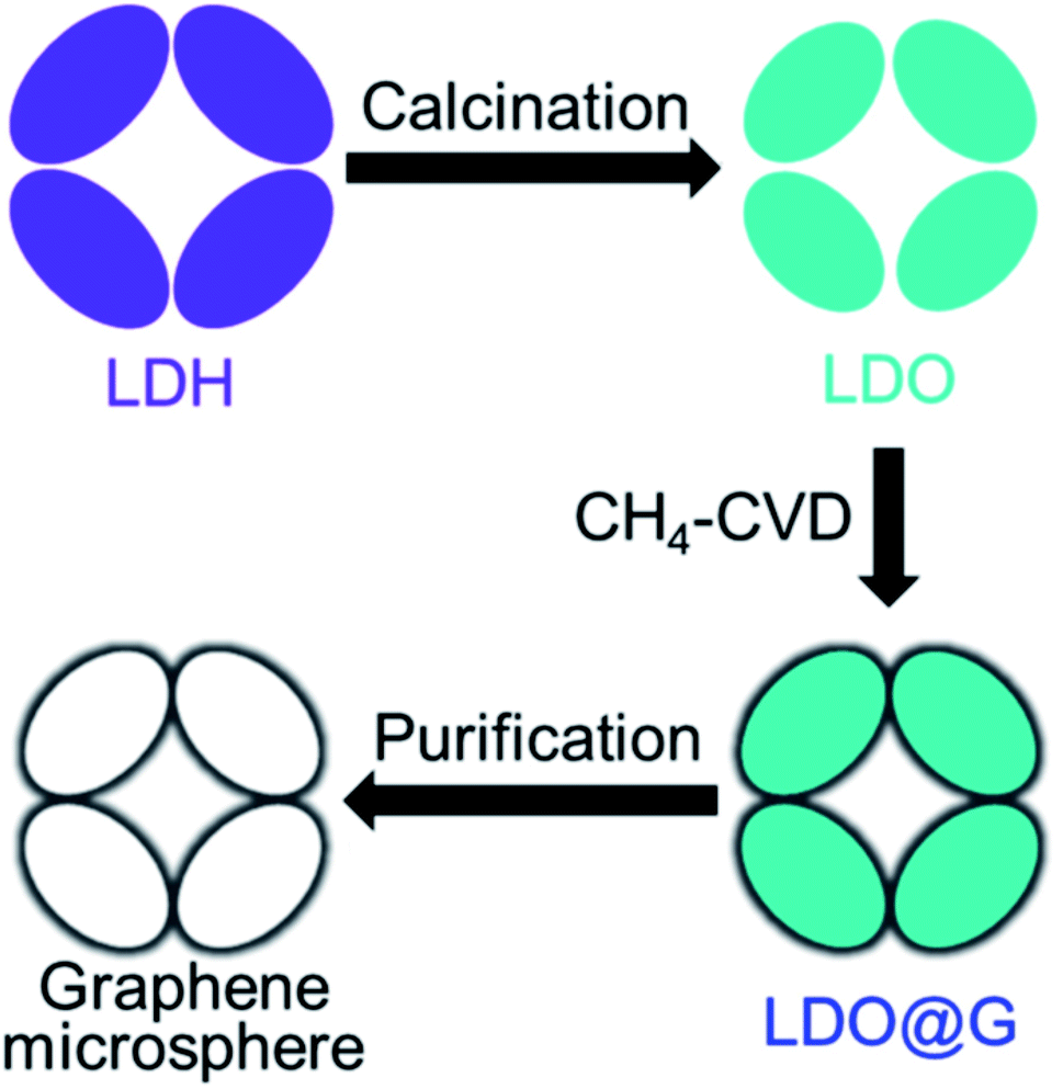 | ||
| Fig. 18 Schematic picture indicating the steps to grow graphene microspheres. Reprinted with permission.109 Copyright 2015, Elsevier. | ||
| Template used | Starting material | Post growth | Final material | Pore size (nm) | SSA (m2 g−1) | Applications | Ref. |
|---|---|---|---|---|---|---|---|
| Amino-functionalized SiO2 | GO | — | N-Doped HG nanocapsules | — | 1162 | Electrocatalysis | Zhang et al.104 |
| Porous MgO layers | — | Graphene growth (CH4 cracking, CVD) | Nanomesh graphene | <10 | 1600–2000 | Ferromagnetism | Ning et al.106 |
| Porous MgO layers | — | Graphene growth (CH4 cracking, CVD) | Nanomesh graphene | <10 | 1654 | Supercapacitor | Ning et al.105 |
| Colloidal microspheres | Graphene | — | Graphene nanomesh | ∼100-few hundred | — | — | Sinitskii et al.107 |
| Polystyrene nanospheres | — | Graphene growth (LPCVD) | Graphene nanomesh | 40 | — | Transistor | Wang et al.108 |
| Layered double oxide microspheres | — | Graphene growth (CVD of CH4) | Porous graphene microsphere | Hierarchical pores | 1275 | Lithium–sulfur battery | Shi et al.109 |
| Hierarchical porous CaO particles | — | Graphene growth (CVD of CH4) | Porous graphene | Hierarchical pores | 572 | Lithium–sulfur battery | Tang et al.110 |
3. Summary of the synthesis methods
As discussed in the previous sections, different synthesis methods have been proposed and demonstrated to create pores in graphene and graphene oxide in the past few years. These methods or approaches have certain advantages and disadvantages, which impact their potential applications.Physical methods such as electron or ion beam can be used to create site-specific pores with precise pore size. The graphene with fabricated pores shows promise for DNA sequencing or permeable membranes. Physical methods, however, have a limitation in terms of the mass-scale fabrication of nanopores. On the other hand, thermal annealing methods such as RTA can create porous graphene from GO or graphene powder on a large scale in a short period. Although the GTA process takes time compared to the RTA method, both annealing methods can be used to obtain high-quality HG material that can be further used in different applications. Chemical methods such as chemical etching agent-assisted processes implement etching acids such as H2O2, HNO3, and KOH to create pores in the range from nm to few microns. This method can be used for the mass-scale production of holey/porous graphene materials and the synthesized material can be further applied as a high performance electrode in LIB or supercapacitor. The nanoparticle-assisted (catalytic oxidation) process is another way to synthesize HG from materials such as GO or graphene. This method uses nanoparticles as a catalyst to synthesize HG. Various groups have also used templates to make patterned holes/pores on graphene sheets. However, template preparation and removal can be tedious and may not be suitable for mass-scale HG fabrication. Table 10 summarizes the different synthesis methods discussed above, the major parameters to control the pore size distribution, the advantages and limitations of the methods, and the major fields where the synthesized materials are used.
| Type | Synthesis method | Pore size | Controlling the pore size distribution | Advantages | Limitations/Disadvantages | Major areas of application |
|---|---|---|---|---|---|---|
| Thermal | Thermal annealing | Few nm–few hundreds of nm | Heating rate, temperature, holding time | Fast (RTA), mass-scale production | GTA usually takes hours | Energy storage (LIB, supercapacitor) |
| Physical | Electron & ion beam | <10 nm–1 μm | Beam diameter, beam energy ion beam type | Precise pore size | Small area fabrication | Atomic-scale application (permeable membrane, DNA sequencing) |
| Chemical | Chemical etching | Few nm–few microns | Reaction time | Mass scale production is possible | The produced material could have impurities | Energy storage (LIB, supercapacitor), water desalination |
| Nanoparticle-assisted oxidation | Few nm–few hundreds of nm | Nanoparticle size | The pore size could be tailored with the size of the nanoparticles | Could be inefficient in mass production | Energy storage (LIB, supercapacitor) | |
| Template directed patterning | Regular pore: <10 nm; hierarchical pores | Etching parameters | Pore size and pore density can be controlled | Template preparation and removal could be complicated | Energy storage |
The bar chart in Fig. 19 further summarizes the scale of the pore size created using different synthesis methods. The high-intensity color value in a bar indicates a higher number of data points or works reported in the literature in a particular pore size range. For example, in the case of chemical methods, the high intensity lies within 10 nm and few works reported pore generation of few hundreds of nm. Similarly, the thermal annealing process mainly allows the generation of pores of few nm to few hundreds of nm. If GTA is used, it, in general, can produce pores of few nm to few tens of nm and the RTA method could generate pores of few nm to few hundreds of nm. Likewise, other bars are also presented and shown in the bar chart. Although different methods can produce pores of various sizes, it can be noticed from the bar chart that the most common or achievable pore sizes are in the range of few nm to tens of nm. The smallest possible pore size that could be created is a few Angstroms (<1 nm),53,56,91 which could be obtained using the electron/ion beam or chemical etching (H2O2) process. On the other hand, the biggest pore size can be of few tens of micron.76
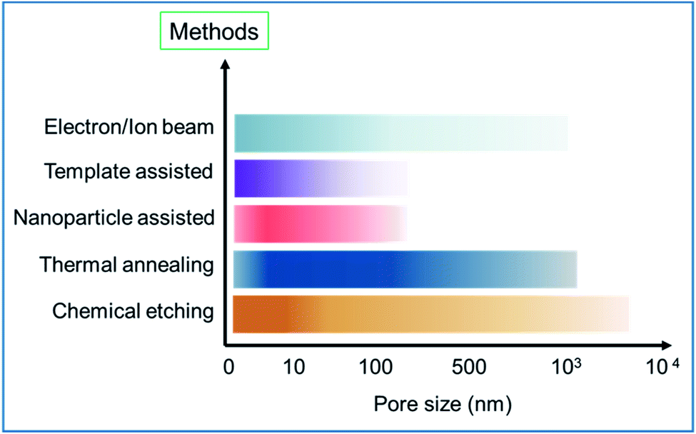 | ||
| Fig. 19 The bar chart shows the different synthesis methods used to create pores of different sizes. | ||
3.1 Controlling the pore size distribution in HG
Having precise control over the pore size distribution, particularly the pore diameter, shape, and periodicity, is essential for the reliable and quality synthesis of HG. When E-beam is used to create micro/nanopores, the pore size can be directly controlled by controlling the beam diameter used in the SEM or TEM. Generally, the intensity in an E-beam follows a Gaussian shape and usually, the size of the beam or, more precisely, the full-width half maximum (FWHM) can be controlled in the microscope itself through the lens optics. In addition, the beam diameter also depends on the beam energy. Thus, the beam energy could play a significant role if a precise hole is needed. Similarly, in the ion beam-assisted pore fabrication process, the pore size can be determined with the beam diameter. The beam energy and the ion type used could also impact the pore size.59,60The annealing method can induce a large number of pores in a short time. The pore size distribution of the grown pores is highly dependent on the heating rate and the temperature. It is found that the size of the pores, as well as the hole density, tend to increase with the heating/ramping rate and the temperature.63,64,69 In addition, the holding time could also impact the pore size distribution.71
When chemical etching agents such as, KOH, HNO3, or H2O2 are used to fabricate pores, the pore size distribution depends on the reaction time. Usually, increasing the reaction time would increase the pore size in the material.84,87 The pore size distribution in the nanoparticle-assisted fabrication process follows the nanoparticle size distribution used during the synthesis process. Thus, the pore size in the material can be tailored with the size of the nanoparticles. On the other hand, the template-assisted chemical etching approach can create well-defined pores with specific periodicity. Consequently, the pore size and pore density can be precisely controlled when the template-based etching process is implemented.
3.2 Controlling defects in HG
Synthesizing HG with controlled defects is an important aspect. Creating vacancies by knocking carbon atoms using an electron beam could result in various processes; for example, a nearby carbon atom can fill up the vacancy or diffusion of the vacancies could take place. Because they exhibit temperature-dependent self-repairing processes, the defects can be controlled by regulating the substrate temperature.49 The study also suggests that the stability of pores has complex dynamics and that zigzag-type edge defects tend to be more stable than armchair defects.51 Molecular dynamics study predicts that when the ion beam is used for pore creation, the beam type and energy could impact the defect formation process in graphene.60 In the case of high-energy ions irradiation, increasing the ion energy reduces the number of structural defects formed in the few-layer graphene films.59 When the annealing process is used for the generation of pores/holes, it is found that the ramping rate and the annealing temperature can impact the defect density in HG. The defect density in HG nanosheets increases with the increase in the ramp rate and the annealing temperature.64,69During chemical etching, for example, when H2O2 is used to create pores from GO sheets, the defects/disorders are found to increase with the doses of H2O2.92 Similar results are also observed when GO is treated with KOH solution.99 The study indicates that more defects are found on the graphene plane when the KOH/GO mass ratio is increased. During the nanoparticle-assisted etching process such as etching GO with ZnO to synthesize holey graphite nanosheets, a higher amount of the catalyst (ZnO) can increase the number of structural defects in the synthesized material.80 In numerous applications, such as in batteries, such defects could help to enhance the electrochemical performance of the cell.81 On the other hand, when nanoparticles or micro/nanospheres are used as a template to create tailored pores, the self-assembly of the particles induces various defects in the material,107 prompting further studies to control the defect formation process.
3.3 Other promising synthesis routes to fabricate HG
In addition to the above discussed commonly reported methods for creating or synthesizing pores in graphene/GO materials, there are also other methods that are being experimented by different research groups. The green synthesis method is a promising approach for the synthesis of HG/porous graphene where various biomaterials such as, Bougainvillea flowers, fungus, biomass or leaves of Plumeria rubra have been used as the starting raw material.111–113 This method is environmentally friendly and likely to be cost-effective as compared to other methods. Electrochemical exfoliation114 and nanoimprint lithography115 methods are also used for the synthesis of HG. Other reported methods such as the sol–gel technique have been used to prepare porous graphene aerogel for capacitor application116 and laser engraving was implemented to create 3D hierarchically porous graphene for supercapacitor electrode application.117 The combustion method is another approach employed to fabricate porous graphene from GO.118 A bottom-up strategy was devised by Moreno et al. to create nanoporous graphene, which showed semiconducting and nanosieving functionalities.119 The trend in the synthesis of the HG material using different approaches as observed in the literature indicates that HG can be obtained by various ways and many of these methods are relatively cheaper with specific advantages and drawbacks.3.4 Tools and techniques to characterize HG
Various techniques have been used for the appropriate characterization of HG. Raman spectroscopy has been one of the primary effective techniques for the structural and chemical characterization of HG. It can essentially figure out the different Stokes' band of graphitic, non-graphitic, and defect-related peaks in such materials. The peak appearing at ∼1350 cm−1 in the Raman spectrum is corresponding to the D-band disorder (defects) in carbon material and the peak that usually appears at ∼1580 cm−1 is the G-band corresponding to the in-plane stretching of sp2 carbon atoms, which signifies the graphitic nature of the carbon material. Another major peak can be often noticed to appear at ∼2700 cm−1, which is a secondary D peak and is assigned as the 2D band, mostly found pronounced in case of monolayer or few layers of graphene; in case of vertically-oriented multilayer graphene sheets, the intensity of the peaks will be determined by the terminated layers.120 Usually, the relative intensity of the D to G peaks can be used to understand the graphitic property of a material. For example, in the synthesized HG material (Fig. 6), the relative intensity of D to G Raman peaks were used to conclude the removal of the defective carbons and formation of quality (highly graphitic) HG material. Thus, by comparing the intensity, their relative positions, and the FWHM of the peaks, various structural properties of the synthesized HG can be evaluated, as demonstrated by various works.59,62,63,93,121Apart from Raman spectroscopy, electron microscopy tools such as SEM and TEM can be used for the assessment of the morphology or to observe the porous nature of the HG materials. On the one hand, SEM can be used for a quick understanding of the material, while TEM can offer intricate information related to the shape, size, or the structural nature of the formed pores in the material.48,77,82 TEM-based electron energy loss spectroscopy (EELS) method can provide chemical information related to the π and σ bonds in the material and their contribution to the material; thus, the presence of sp2 and sp3 carbons can be evaluated with atomic scale spatial resolution.96 Techniques such as X-ray diffraction (XRD) could be used to understand the crystalline nature of the material, variation of the interlayer spacings of HG with the synthesis parameters, etc.73,91,100 Another important parameter that is often required is the evolution of the porosity or distribution of the pores in the material. BET or the Barret–Joyner–Halenda (BET/BJH) method is mostly considered for the evaluation of such information from an HG material. Information such as pore size distribution, average pore size, pore density, etc., can be obtained from BET/BJH analysis.11,71,83
4. Applications of HG
Due to the various exciting and unique properties of HG, they have been considered in different fields, mainly focusing on energy storage, water permeance and desalination, carbon capture, and DNA sequencing.The high surface area of HG/porous graphene and the presence of interchannels for ionic/molecular movement are unique properties of HG. In addition, the interlayer attractions in HG are relatively weaker due to the lack of sufficient number of carbon atoms and the interlayer distance is higher than other forms of graphene. These properties instigated its use instead of graphene in lithium-ion batteries (LIB). Conventional graphite-based LIBs have a theoretical specific capacity of 372 mA h g−1. This value can be improved by changing the anode materials such as carbon nanotubes, porous carbons, or graphene. Graphene can provide higher capacity due to its high specific surface area. A single layer of graphene has a theoretical surface area of 2630 m2 g−1. However, the performance of the graphene anode is hindered as the graphene layers tend to restack, which results in the decrease in the available surface area for Li-ion intercalation. Hence, HG, when used as an anode/electrode in batteries or capacitors, significantly enhances the efficiency of the device, as demonstrated by various works.41,42,74,87,88,122–125 It is now well known that the degree of microporosity, specific surface area, and surface wettability of a grown porous graphene material play a key role in the capacitance in a capacitor.99 The efficiency of HG as an energy storage electrode can be further enhanced by doping with other elements such as nitrogen, sulfur, and phosphorus.65,126,127
DNA sequencing is currently an important field in biological sciences, which can benefit from the development of nanopore graphene membranes.128 When DNA passes through a membrane, there are changes in the ionic current. This change depends on the shape, size, and length of the DNA.129–131 The ideal size of a nanogap for DNA to pass through is a few nm, ∼1.0–1.5 nm,132 which could be achieved in the case of HG/porous graphene. The most effective method to create precise nanopores for DNA sequencing has been found to be the electron or ion beam-assisted physical removal of carbon atoms.52,61,133,134 However, the created nanopores could be unstable due to the presence of unsaturated bonds. It has been reported that by passivating the dangling carbon bonds with Si atoms, these pores could be made stable.135
Another primary application of HG or porous graphene is in water desalination. The porous nature of the material can be used for water permanence and hence in the production of fresh water from impure water. Several studies indicated the effectiveness of using holey GO and HG in such applications.15,16,38,136,137 When ion-containing water is allowed to pass through the graphene sheets, the larger ions can be blocked from passing through the pores. In this case, the pore size distribution is the critical factor determining the permeation of water molecules but not the ions. This is shown schematically in Fig. 20a.
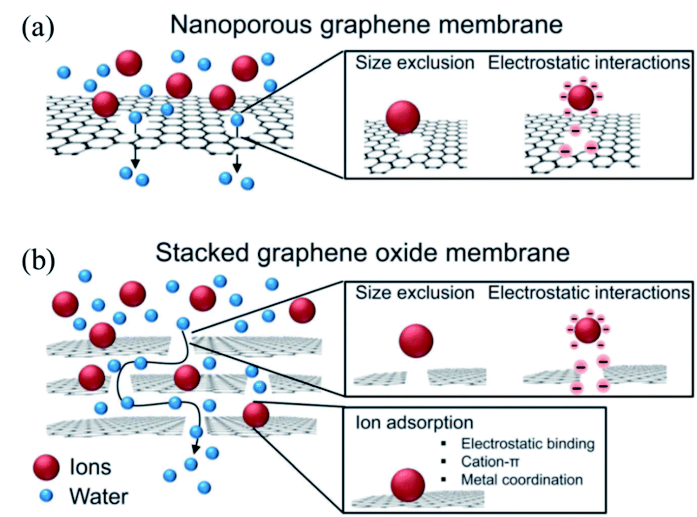 | ||
| Fig. 20 Water purification via ion filtering using nanoporous graphene (a) and stacked graphene oxide (b). Reprinted with permission.33 Copyright 2015, Royal Society of Chemistry. | ||
Along with the porous nature of the material, the interlayer distance, particularly in GO or rGO, can also play a significant role in the water desalination process.28,33,138–140 GO/rGO membranes are found to be stable in water141,142 and have high water permeance properties.143–145 These properties of GO or rGO can be further enhanced or modulated by creating pores in the materials. This is shown in the schematic Fig. 20b below, where stacked graphene oxide (GO) acts as a filter for water molecules.
Solar power-assisted water purification is another advanced and promising field of research for an eco-friendly and sustainable future. 2D nanomaterials are suitable for such applications due to their efficient photothermal, broad band absorption, and photocatalytic transformation, in addition to the larger surface area that they can offer.146,147 A recent study by Yang et al. demonstrated a solar energy convertor for water desalination using a 3D cross-linked polymer-like (porous-graphene) material.148 In a separate work, a membrane of porous graphene and polyimide was prepared with a 3D architecture.149 The membrane with the 3D structure displayed excellent solar absorption capability; on the other hand, the 3D porous network boosts water vapor escape. Ito et al. designed a porous graphene material-based steam generator.150 The generator can convert sunlight into high-energy steam at a promisingly high energy efficiency of 80%.
It is also reported that photocatalytic activity of a photocatalyst material such as TiO2 can be further enhanced if the photocatalyst material is mixed with HG.92 The presence of holes allows light permeation and reactant diffusion, and enhances the photocatalytic properties. While using in combination with ZnO nanoparticles, porous graphene promotes the effective charge separation of electron–hole pairs and increases the photocatalytic performance.151 Similarly, nanocomposites of three-dimensional porous graphene and Co3O4 were used for high-performance photocatalysis.152
The porous form of graphene can also help in the storage of hydrogen.153 It is believed that the hydrogen storage mechanism varies from sample to sample.154 The interaction between hydrogen and carbon materials is governed by van der Waals force. This attractive force could lead to physisorption. If hydrogen comes very close to the carbon atoms, then this could lead to the overlapping of wave functions of carbon atoms with those of the hydrogen electron. This can lead to the chemisorption of hydrogen on the carbon material.
Graphene membranes with nanopores have been applied in the field of gas separation for the filtration of CO2 gas molecules from other gases. This was achieved by tailoring the pores to allow the CO2 molecules to pass while blocking other gases such as NO2.155,156
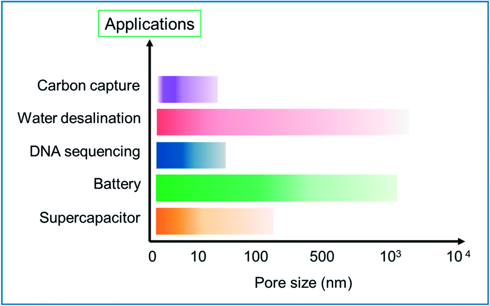
In general, the scale of the pore size could impact on the field of application of the HG. This is visually represented in the bar chart in Fig. 21. The chart is a summary of the different major synthesis methods and tables discussed in this review paper. The intensity in the bars is corresponding to the number of results reported. The chart provides a rough estimation of the scale of pores created for specific applications. In the supercapacitor application, the pore sizes designed are in the range of few nm and mostly <10 nm. Similarly, the pores created for battery application are in the range of a few nm to few hundreds of nm. For DNA sequencing and translocating, pores with a small size in the range of a few nm are needed, which could be precisely fabricated using an energetic electron or ion beam. For water desalination applications, the typical pore size depends on the type of desalination technology the membrane is intended for; e.g., reverse osmosis membranes require pore sizes less than 1 nm for efficient salt removal, whereas nano or microfiltration membranes typically have larger pores. Similarly, for application in carbon capture, the scale of the pores is narrower and can be few nm.
 | ||
| Fig. 21 Bar chart showing the different fields of application vs. the pore size of HG being tested. | ||
In addition to the above-mentioned areas where HG has been successfully used, the unique structural configuration and properties of HG/porous graphene have found various potential applications in areas such as in solar cells,157,158 field-effect transistors (FET),115,159 fuel cells,160 and microwave absorption.161–164 Graphene is a desirable material for gas sensing applications.165–167 By creating pores in the graphene or GO material, the sensing performance can be efficiently enhanced.168,169 There are also other unique applications of HG. For example, a high-efficiency thermocell device was designed by Li et al. that was capable of working at temperatures as low as −40 °C.170 HG was also demonstrated as an efficient planar field emitter.171 The applied field concentrates along the circumference of the holes and provides field emission sites. In an interesting work by Chen et al., an hrGO-based FET type device was made to detect the bacteria.172 The hrGO material with p-type semiconductor properties was used as the transducer element in the FET device. The device could detect E. coli bacteria with a detection limit as low as 803 cfu mL−1. In a separate work, graphene oxide nanomesh (GONM) was synthesized to treat cancer cells.173 GONM was initially developed using photocatalytic degradation and subsequently functionalized by mixing with polyethylene glycol (PEG), arginine-glycine–aspartic acid (RGD)-based peptide and cyanine 7 (Cy7). The composite has strong absorption in the NIR range and thus, when the tumor cells targeted by the composite were irradiated with low power laser, cell ablation occurred. In this way, the cancer cells could be treated successfully. The unique material properties and versatile nature of applications of HG make it a potential field for researchers to investigate and explore further.
Similar to graphene with pores, other 2D materials with pores could be fabricated and used in different fields. For example, 2D materials such as Ti3C2Tx foam with pores could be used as the electromagnetic shielding material.174 In the optoelectronics sector, 2D semiconductors have shown promising results, mainly due to their exhibition of many-body complexes such as exciton, trion, and biexcitor.175 Optical properties along with their device applications of several 2D materials are well-reviewed.176–178 Modulating these properties by engineering the materials could open up new avenues of applications. Similarly, the optoelectronic properties of HG have not been well studied and remain an undiscovered field that needs more attention. MXene is an emerging 2D material and is a promising field for several types of applications.179 The review paper179 discusses various exciting properties of MXene along with several other applications of porous MXenes such as porous MXene with hierarchical structures for enhanced oxygen evolution reaction (OER), 3D interconnected porous frameworks of MXene with a high specific area for energy storage, and EMI applications. The studies suggest that similar to the emerging 2D semiconductor field, HG with tunable properties is a potential and untouched field that needs more research.
5. Conclusions and future outlook
HG is an emerging new material with exciting and unique properties that could find potential applications in different fields including semiconductor industry, water purification, solar cell, fuel cell, DNA sequencing, and energy storage. Several synthesis methods have been developed over the past few years and in this review work, we have summarized the most promising approaches and their technological applications in different fields. The synthesis/fabrication methods are systematically categorized to benefit the readers and help them understand the type of holes/pores generated, various parameters to control the pore size distribution, and their potential applications in different fields. In specific applications, such as DNA sequencing, devices have to be made out of a monolayer or few layers of graphene, for which the synthesis of high-quality graphene is needed. However, for most of the other applications, the bulk material of holey/porous graphene could be prepared at a significantly low cost. Synthesis methods such as annealing or chemical approaches have the potential to produce HG in the bulk form, which could be later used in the field of energy storage, water purification, etc. In these methods, GO or graphitic powder can be used as a starting material. GO has been a common starting material for the synthesis of HG and due to the low production cost of GO; the overall cost of HG synthesis could be a fraction of that of CVD-grown graphene.180–182 In addition, most synthesis methods exploit the presence of structural defects in the graphene layers. Such defects have been reported to facilitate the formation of pores. Accordingly, the precursor for HG or HGO does not need to be the most expensive form of graphene.Despite being a promising emerging versatile material, there are certain aspects of HG that the research community should address before it can be commercially produced for various applications. One of the aspects is the systematic study of the pore production to tailor and generate precise pores by cost-effective methods such as annealing since a well-defined pore distribution is highly desirable in many applications. Understanding the structural degradation of the synthesized HG under certain conditions such as long-term performance in water purification or the change in the inherent optoelectronic property with the environment is also essential. Broader in-depth studies focused on specific applications are thus needed. HG and composites of HG have shown promising results in energy storage applications primarily due to the increased specific surface area. This field can be further developed and thoroughly researched with the combination of porous/HG and nanoparticles with hierarchical sizes (<2 nm to a few μm). The relation between the performance and pore size distribution as well as the nanoparticle size needs to be understood. At last, there are more approaches that are yet to be developed that could produce well-defined holey/porous graphene material, which should be economical, less time consuming, and thus, should have mass-scale production capability.
Data availability
Data will be provided upon request.Conflicts of interest
There are no conflicts to declare.Acknowledgements
The authors thank Abu Dhabi Government's Advanced Technology Research Council (ATRC), which oversees technology research in the emirate.References
- M. Sang, J. Shin, K. Kim and K. J. Yu, Nanomaterials, 2019, 9, 374 CrossRef CAS PubMed.
- D. G. Papageorgiou, I. A. Kinloch and R. J. Young, Prog. Mater. Sci., 2017, 90, 75–127 CrossRef CAS.
- A. K. Geim and K. S. Novoselov, Nat. Mater., 2007, 6, 183–191 CrossRef CAS PubMed.
- L. Lin, H. Peng and Z. Liu, Nat. Mater., 2019, 18, 520–524 CrossRef CAS PubMed.
- C. Dean, A. F. Young, L. Wang, I. Meric, G. H. Lee, K. Watanabe, T. Taniguchi, K. Shepard, P. Kim and J. Hone, Solid State Commun., 2012, 152, 1275–1282 CrossRef CAS.
- M. Yankowitz, Q. Ma, P. Jarillo-Herrero and B. J. LeRoy, Nat. Rev. Phys., 2019, 1, 112–125 CrossRef CAS.
- A. K. Geim and I. V. Grigorieva, Nature, 2013, 499, 419–425 CrossRef CAS PubMed.
- F. Ye, J. Lee and P. X. L. Feng, Nanoscale, 2017, 9, 18208–18215 RSC.
- P. M. Pataniya and C. K. Sumesh, ACS Appl. Nano Mater., 2020, 3, 6935–6944 CrossRef CAS.
- Y. Tao, Z.-Y. Sui and B.-H. Han, J. Mater. Chem. A, 2020, 8, 6125–6143 RSC.
- E. D. Walsh, X. Han, S. D. Lacey, J.-W. Kim, J. W. Connell, L. Hu and Y. Lin, ACS Appl. Mater. Interfaces, 2016, 8, 29478–29485 CrossRef CAS PubMed.
- Z. Xing, J. Tian, Q. Liu, A. M. Asiri, P. Jiang and X. Sun, Nanoscale, 2014, 6, 11659–11663 RSC.
- S. P. Surwade, S. N. Smirnov, I. V. Vlassiouk, R. R. Unocic, G. M. Veith, S. Dai and S. M. Mahurin, Nat. Nanotechnol., 2015, 10, 459–464 CrossRef CAS PubMed.
- A. Boretti, S. Al-Zubaidy, M. Vaclavikova, M. Al-Abri, S. Castelletto and S. Mikhalovsky, npj Clean Water, 2018, 1, 5 CrossRef CAS.
- Z. Fa, IOP Conf. Ser.: Mater. Sci. Eng., 2020, 926, 012011 CAS.
- D. Cohen-Tanugi and J. C. Grossman, Nano Lett., 2012, 12, 3602–3608 CrossRef CAS PubMed.
- R. O. Brennan, J. Chem. Phys., 1952, 20, 40–48 CrossRef CAS.
- T. Gould, K. Simpkins and J. F. Dobson, Phys. Rev. B, 2008, 77, 165134 CrossRef.
- G. L. Klimchitskaya, U. Mohideen and V. M. Mostepanenko, Phys. Rev. A, 2000, 61, 062107 CrossRef.
- L. G. MacDowell, J. Chem. Phys., 2019, 150, 081101 CrossRef PubMed.
- G. L. Klimchitskaya and V. M. Mostepanenko, Phys. Rev. B, 2013, 87, 075439 CrossRef.
- Y. Ding, Y. Wang, S. Shi and W. Tang, J. Phys. Chem. C, 2011, 115, 5334–5343 CrossRef CAS.
- A. Du, Z. Zhu and S. C. Smith, J. Am. Chem. Soc., 2010, 132, 2876–2877 CrossRef CAS PubMed.
- D. Singh, V. Shukla and R. Ahuja, Phys. Rev. B, 2020, 102, 075444 CrossRef CAS.
- P. A. Denis, R. Faccio and F. Iribarne, Comput. Theor. Chem., 2012, 995, 1–7 CrossRef CAS.
- L. Huang, S. Miao, X. Wang and X. Yang, Mol. Simul., 2020, 46, 853–863 CrossRef CAS.
- P. A. Denis and F. Iribarne, J. Phys. Chem. C, 2013, 117, 19048–19055 CrossRef CAS.
- Y. Qian, X. Zhang, C. Liu, C. Zhou and A. Huang, Desalination, 2019, 460, 56–63 CrossRef CAS.
- T. Liu, L. Tian, N. Graham, B. Yang, W. Yu and K. Sun, Environ. Sci. Technol., 2019, 53, 11949–11959 CrossRef CAS PubMed.
- F. Changjing, G. Zhao, H. Zhang and S. Li, Int. J. Electrochem. Sci., 2013, 8, 6269–6280 Search PubMed.
- S. Rao, J. Upadhyay, K. Polychronopoulou, R. Umer and R. Das, J. Compos. Sci., 2018, 2, 25 CrossRef.
- A. Abid, P. Sehrawat, S. S. Islam, P. Mishra and S. Ahmad, Sci. Rep., 2018, 8, 3537 CrossRef PubMed.
- F. Perreault, A. Fonseca de Faria and M. Elimelech, Chem. Soc. Rev., 2015, 44, 5861–5896 RSC.
- B. Lesiak, G. Trykowski, J. Tóth, S. Biniak, L. Kövér, N. Rangam, L. Stobinski and A. Malolepszy, J. Mater. Sci., 2021, 56, 3738–3754 CrossRef CAS.
- V. H. Luan, H. N. Tien, L. T. Hoa, N. T. M. Hien, E.-S. Oh, J. Chung, E. J. Kim, W. M. Choi, B.-S. Kong and S. H. Hur, J. Mater. Chem. A, 2013, 1, 208–211 RSC.
- A. M. Selim, M. A. Wasfey, H. H. Abduallah, M. B. Zahran, W. Khalifa and I. S. El-Mahallawi, 2019 6th International Conference on Advanced Control Circuits and Systems (ACCS) & 2019 5th International Conference on New Paradigms in Electronics & information Technology (PEIT), 2019, pp. 94–98 Search PubMed.
- K. A. Sammed, L. Pan, M. Asif, M. Usman, T. Cong, F. Amjad and M. A. Imran, Sci. Rep., 2020, 10, 2315 CrossRef PubMed.
- X. Chen, Z. Feng, J. Gohil, C. M. Stafford, N. Dai, L. Huang and H. Lin, ACS Appl. Mater. Interfaces, 2020, 12, 1387–1394 CrossRef CAS PubMed.
- M. Yang, Y. Wang, L. Dong, Z. Xu, Y. Liu, N. Hu, E. S.-W. Kong, J. Zhao and C. Peng, Nanoscale Res. Lett., 2019, 14, 218 CrossRef PubMed.
- J. Zhao, Y.-Z. Zhang, F. Zhang, H. Liang, F. Ming, H. N. Alshareef and Z. Gao, Adv. Energy Mater., 2019, 9, 1803215 CrossRef.
- X. Hu, D. Bai, Y. Wu, S. Chen, Y. Ma, Y. Lu, Y. Chao and Y. Bai, Chem. Commun., 2017, 53, 13225–13228 RSC.
- T. Liu, L. Zhang, B. Cheng, X. Hu and J. Yu, Cell Rep. Phys. Sci., 2020, 1, 100215 CrossRef CAS.
- A. C. Lokhande, I. A. Qattan, C. D. Lokhande and S. P. Patole, J. Mater. Chem. A, 2020, 8, 918–977 RSC.
- Y. Lin, Y. Liao, Z. Chen and J. W. Connell, Mater. Res. Lett., 2017, 5, 209–234 CrossRef CAS.
- Y. Zhang, Q. Wan and N. Yang, Small, 2019, 15, 1903780 CrossRef CAS PubMed.
- P. Ramos Ferrer, A. Mace, S. N. Thomas and J.-W. Jeon, Nano Convergence, 2017, 4, 29 CrossRef PubMed.
- J. Rouquerol, D. Avnir, C. W. Fairbridge, D. H. Everett, J. M. Haynes, N. Pernicone, J. D. F. Ramsay, K. S. W. Sing and K. K. Unger, Pure Appl. Chem., 1994, 66, 1739–1758 CAS.
- M. D. Fischbein and M. Drndić, Appl. Phys. Lett., 2008, 93, 113107 CrossRef.
- B. Song, G. F. Schneider, Q. Xu, G. Pandraud, C. Dekker and H. Zandbergen, Nano Lett., 2011, 11, 2247–2250 CrossRef CAS PubMed.
- D. Fox, A. O'Neill, D. Zhou, M. Boese, J. N. Coleman and H. Z. Zhang, Appl. Phys. Lett., 2011, 98, 243117 CrossRef.
- Ç. Ö. Girit, J. C. Meyer, R. Erni, M. D. Rossell, C. Kisielowski, L. Yang, C.-H. Park, M. F. Crommie, M. L. Cohen, S. G. Louie and A. Zettl, Science, 2009, 323, 1705 CrossRef PubMed.
- G. F. Schneider, S. W. Kowalczyk, V. E. Calado, G. Pandraud, H. W. Zandbergen, L. M. K. Vandersypen and C. Dekker, Nano Lett., 2010, 10, 3163–3167 CrossRef CAS PubMed.
- C. J. Russo and J. A. Golovchenko, Proc. Natl. Acad. Sci., 2012, 109, 5953 CrossRef CAS PubMed.
- H. Wang, K. Kurata, T. Fukunaga, H. Takamatsu, X. Zhang, T. Ikuta, K. Takahashi, T. Nishiyama, H. Ago and Y. Takata, Carbon, 2016, 99, 564–570 CrossRef CAS.
- K. Celebi, J. Buchheim, R. M. Wyss, A. Droudian, P. Gasser, I. Shorubalko, J.-I. Kye, C. Lee and H. G. Park, Science, 2014, 344, 289 CrossRef CAS PubMed.
- S. C. O'Hern, M. S. H. Boutilier, J.-C. Idrobo, Y. Song, J. Kong, T. Laoui, M. Atieh and R. Karnik, Nano Lett., 2014, 14, 1234–1241 CrossRef PubMed.
- H. Vázquez, E. H. Åhlgren, O. Ochedowski, A. A. Leino, R. Mirzayev, R. Kozubek, H. Lebius, M. Karlušic, M. Jakšic, A. V. Krasheninnikov, J. Kotakoski, M. Schleberger, K. Nordlund and F. Djurabekova, Carbon, 2017, 114, 511–518 CrossRef.
- D. K. Avasthi, Curr. Sci., 2000, 78, 1297–1303 CAS.
- N. A. Nebogatikova, I. V. Antonova, S. V. Erohin, D. G. Kvashnin, A. Olejniczak, V. A. Volodin, A. V. Skuratov, A. V. Krasheninnikov, P. B. Sorokin and L. A. Chernozatonskii, Nanoscale, 2018, 10, 14499–14509 RSC.
- W. Li, L. Liang, S. Zhao, S. Zhang and J. Xue, J. Appl. Phys., 2013, 114, 234304 CrossRef.
- S. Garaj, S. Liu, J. A. Golovchenko and D. Branton, Proc. Natl. Acad. Sci., 2013, 110, 12192 CrossRef CAS PubMed.
- J. Buchheim, R. M. Wyss, I. Shorubalko and H. G. Park, Nanoscale, 2016, 8, 8345–8354 RSC.
- Y.-Y. Peng, Y.-M. Liu, J.-K. Chang, C.-H. Wu, M.-D. Ger, N.-W. Pu and C.-L. Chang, Carbon, 2015, 81, 347–356 CrossRef CAS.
- C.-H. Wu, N.-W. Pu, Y.-M. Liu, C.-Y. Chen, Y.-Y. Peng, T.-Y. Cheng, M.-H. Lin and M.-D. Ger, J. Taiwan Inst. Chem. Eng., 2017, 80, 511–517 CrossRef CAS.
- F. Su, S. Zheng, F. Liu, X. Zhang, F. Su and Z.-S. Wu, Chin. Chem. Lett., 2021, 32, 914–917 CrossRef CAS.
- C.-H. Yang, P.-L. Huang, X.-F. Luo, C.-H. Wang, C. Li, Y.-H. Wu and J.-K. Chang, ChemSusChem, 2015, 8, 1779–1786 CrossRef CAS PubMed.
- B. Xing, H. Zeng, G. Huang, C. Zhang, R. Yuan, Y. Cao, Z. Chen and J. Yu, J. Alloys Compd., 2019, 779, 202–211 CrossRef CAS.
- D. Zhou, Q.-Y. Cheng and B.-H. Han, Carbon, 2011, 49, 3920–3927 CrossRef CAS.
- X.-F. Luo, C.-H. Yang and J.-K. Chang, J. Mater. Chem. A, 2015, 3, 17282–17289 RSC.
- Y.-R. Huang, C.-L. Chen, N.-W. Pu, C.-H. Wu, Y.-M. Liu, Y.-H. Chen, M.-J. Youh and M.-D. Ger, Crystals, 2020, 10, 1063 CrossRef CAS.
- X. Han, M. R. Funk, F. Shen, Y.-C. Chen, Y. Li, C. J. Campbell, J. Dai, X. Yang, J.-W. Kim, Y. Liao, J. W. Connell, V. Barone, Z. Chen, Y. Lin and L. Hu, ACS Nano, 2014, 8, 8255–8265 CrossRef CAS PubMed.
- Y. Lin, X. Han, C. J. Campbell, J.-W. Kim, B. Zhao, W. Luo, J. Dai, L. Hu and J. W. Connell, Adv. Funct. Mater., 2015, 25, 2920–2927 CrossRef CAS.
- Y. Jin, C. Hu, Q. Dai, Y. Xiao, Y. Lin, J. W. Connell, F. Chen and L. Dai, Adv. Funct. Mater., 2018, 28, 1804630 CrossRef.
- J. Xu, Y. Lin, J. W. Connell and L. Dai, Small, 2015, 11, 6179–6185 CrossRef CAS PubMed.
- Y. Chen, Y. Wang, S. Zhu, K. Fu, X. Han, Y. Wang, B. Zhao, T. Li, B. Liu, Y. Li, J. Dai, H. Xie, T. Li, J. W. Connell, Y. Lin and L. Hu, Mater. Today, 2019, 24, 26–32 CrossRef CAS.
- F. Xiao, X. Chen, J. Zhang, C. Huang, T. Hu, B. Hong and J. Xu, J. Energy Chem., 2020, 48, 122–127 CrossRef.
- Y. Lin, K. A. Watson, J.-W. Kim, D. W. Baggett, D. C. Working and J. W. Connell, Nanoscale, 2013, 5, 7814–7824 RSC.
- E. Alsharaeh, F. Ahmed, Y. Aldawsari, M. Khasawneh, H. Abuhimd and M. Alshahrani, Sci. Rep., 2016, 6, 29854 CrossRef CAS PubMed.
- W. Seo, D. L. White and A. Star, Chem.–Eur. J., 2017, 23, 5652–5657 CrossRef CAS PubMed.
- J. Wang, T. Park, J. W. Yi, B. Ding, J. Henzie, Z. Chang, H. Dou, X. Zhang and Y. Yamauchi, Nanoscale Horiz., 2019, 4, 526–530 RSC.
- Z. Du, W. Ai, C. Sun, C. Zou, J. Zhao, Y. Chen, X. Dong, J. Liu, G. Sun, T. Yu and W. Huang, ACS Appl. Mater. Interfaces, 2016, 8, 33712–33722 CrossRef CAS PubMed.
- D. Dutta, J.-Y. Jiang, A. Jamaluddin, S.-M. He, Y.-H. Hung, F. Chen, J.-K. Chang and C.-Y. Su, ACS Appl. Mater. Interfaces, 2019, 11, 36560–36570 CrossRef CAS PubMed.
- X. Zhao, C. M. Hayner, M. C. Kung and H. H. Kung, ACS Nano, 2011, 5, 8739–8749 CrossRef CAS PubMed.
- X. Wang, L. Jiao, K. Sheng, C. Li, L. Dai and G. Shi, Sci. Rep., 2013, 3, 1996 CrossRef PubMed.
- J.-H. Chang, Y.-H. Hung, X.-F. Luo, C.-H. Huang, S. Jung, J.-K. Chang, J. Kong and C.-Y. Su, RSC Adv., 2016, 6, 8384–8394 RSC.
- S. Chowdhury and R. Balasubramanian, Sci. Rep., 2016, 6, 21537 CrossRef CAS PubMed.
- Y. Xu, C.-Y. Chen, Z. Zhao, Z. Lin, C. Lee, X. Xu, C. Wang, Y. Huang, M. I. Shakir and X. Duan, Nano Lett., 2015, 15, 4605–4610 CrossRef CAS PubMed.
- Y. Xu, Z. Lin, X. Zhong, X. Huang, N. O. Weiss, Y. Huang and X. Duan, Nat. Commun., 2014, 5, 4554 CrossRef CAS PubMed.
- J. Lv and T. Liang, Chem. Phys. Lett., 2016, 659, 61–65 CrossRef CAS.
- W. Kong, X. Duan, Y. Ge, H. Liu, J. Hu and X. Duan, Nano Res., 2016, 9, 2458–2466 CrossRef CAS.
- T. Palaniselvam, M. O. Valappil, R. Illathvalappil and S. Kurungot, Energy Environ. Sci., 2014, 7, 1059–1067 RSC.
- C. Xu, X. He, C. Wang, X. Chen, R. Yuan and W. Dai, RSC Adv., 2016, 6, 84068–84073 RSC.
- D. Wang, R. Dai, X. Zhang, L. Liu, H. Zhuang, Y. Lu, Y. Wang, Y. Liao and Q. Nian, Carbon, 2020, 161, 880–891 CrossRef CAS.
- D. C. Marcano, D. V. Kosynkin, J. M. Berlin, A. Sinitskii, Z. Sun, A. Slesarev, L. B. Alemany, W. Lu and J. M. Tour, ACS Nano, 2010, 4, 4806–4814 CrossRef CAS PubMed.
- M. A. Lillo-Ródenas, D. Cazorla-Amorós and A. Linares-Solano, Carbon, 2003, 41, 267–275 CrossRef.
- Y. Zhu, S. Murali, M. D. Stoller, K. J. Ganesh, W. Cai, P. J. Ferreira, A. Pirkle, R. M. Wallace, K. A. Cychosz, M. Thommes, D. Su, E. A. Stach and R. S. Ruoff, Science, 2011, 332, 1537 CrossRef CAS PubMed.
- L. Chunlan, X. Shaoping, G. Yixiong, L. Shuqin and L. Changhou, Carbon, 2005, 43, 2295–2301 CrossRef.
- L. Xu, W. Lv, K. Shi, S. Xiao, C. You, Y.-B. He, F. Kang and Q.-H. Yang, Carbon, 2019, 149, 257–262 CrossRef CAS.
- K. Xia, Q. Li, L. Zheng, K. You, X. Tian, B. Han, Q. Gao, Z. Huang, G. Chen and C. Zhou, Microporous Mesoporous Mater., 2017, 237, 228–236 CrossRef CAS.
- C. Zheng, X. F. Zhou, H. L. Cao, G. H. Wang and Z. P. Liu, J. Mater. Chem. A, 2015, 3, 9543–9549 RSC.
- I. A. Baburin, A. Klechikov, G. Mercier, A. Talyzin and G. Seifert, Int. J. Hydrogen Energy, 2015, 40, 6594–6599 CrossRef CAS.
- S. Wu, K. S. Hui, K. N. Hui, J. M. Yun and K. H. Kim, Chem. Eng. J., 2017, 317, 461–470 CrossRef CAS.
- Z. Jiang, B. Pei and A. Manthiram, J. Mater. Chem. A, 2013, 1, 7775–7781 RSC.
- Z. Zhang, T. Cao, S. Liu, X. Duan, L.-M. Liu, S. Wang and Y. Liu, Part. Part. Syst. Charact., 2017, 34, 1600207 CrossRef.
- G. Ning, Z. Fan, G. Wang, J. Gao, W. Qian and F. Wei, Chem. Commun., 2011, 47, 5976–5978 RSC.
- G. Ning, C. Xu, L. Hao, O. Kazakova, Z. Fan, H. Wang, K. Wang, J. Gao, W. Qian and F. Wei, Carbon, 2013, 51, 390–396 CrossRef CAS.
- A. Sinitskii and J. M. Tour, J. Am. Chem. Soc., 2010, 132, 14730–14732 CrossRef CAS PubMed.
- M. Wang, L. Fu, L. Gan, C. Zhang, M. Rümmeli, A. Bachmatiuk, K. Huang, Y. Fang and Z. Liu, Sci. Rep., 2013, 3, 1238 CrossRef PubMed.
- J.-L. Shi, H.-J. Peng, L. Zhu, W. Zhu and Q. Zhang, Carbon, 2015, 92, 96–105 CrossRef CAS.
- C. Tang, B.-Q. Li, Q. Zhang, L. Zhu, H.-F. Wang, J.-L. Shi and F. Wei, Adv. Funct. Mater., 2016, 26, 577–585 CrossRef CAS.
- R. P. Panmand, P. Patil, Y. Sethi, S. R. Kadam, M. V. Kulkarni, S. W. Gosavi, N. R. Munirathnam and B. B. Kale, Nanoscale, 2017, 9, 4801–4809 RSC.
- H. Zhu, X. Wang, F. Yang and X. Yang, Adv. Mater., 2011, 23, 2745–2748 CrossRef CAS PubMed.
- Y. Wang, T. Song, P. Zhang, T. Huang, T. Wang, T. Wang and H. Zeng, ACS Sustainable Chem. Eng., 2018, 6, 11536–11546 CrossRef CAS.
- A.-K. Lu, H.-Y. Li and Y. Yu, J. Mater. Chem. A, 2019, 7, 7852–7858 RSC.
- X. Liang, Y.-S. Jung, S. Wu, A. Ismach, D. L. Olynick, S. Cabrini and J. Bokor, Nano Lett., 2010, 10, 2454–2460 CrossRef CAS PubMed.
- H. Yang, C. Zhang, Q. Meng, B. Cao and G. Tian, J. Power Sources, 2019, 431, 114–124 CrossRef CAS.
- F. Wang, X. Mei, K. Wang, X. Dong, M. Gao, Z. Zhai, J. Lv, C. Zhu, W. Duan and W. Wang, J. Mater. Sci., 2019, 54, 5658–5670 CrossRef CAS.
- Z. Li, X. Zhang, H. Tan, W. Qi, L. Wang, M. C. Ali, H. Zhang, J. Chen, P. Hu, C. Fan and H. Qiu, Adv. Funct. Mater., 2018, 28, 1805026 CrossRef.
- C. Moreno, M. Vilas-Varela, B. Kretz, A. Garcia-Lekue, M. V. Costache, M. Paradinas, M. Panighel, G. Ceballos, S. O. Valenzuela, D. Peña and A. Mugarza, Science, 2018, 360, 199 CrossRef CAS PubMed.
- A. Al-Hagri, R. Li, N. S. Rajput, J.-Y. Lu, S. Cong, K. Sloyan, M. A. Almahri, S. R. Tamalampudi, M. Chiesa and A. Al Ghaferi, Carbon, 2019, 155, 320–325 CrossRef CAS.
- X. J. Lee, B. Y. Z. Hiew, K. C. Lai, L. Y. Lee, S. Gan, S. Thangalazhy-Gopakumar and S. Rigby, J. Taiwan Inst. Chem. Eng., 2019, 98, 163–180 CrossRef CAS.
- C. Zhu, Z. Hui, H. Pan, S. Zhu, Q. Zhang, J. Mao, Z. Guo, Y. Li, M. Imtiaz and Z. Chen, J. Mater. Chem. A, 2019, 7, 4788–4796 RSC.
- Y. Lin, B. Moitoso, C. Martinez-Martinez, E. D. Walsh, S. D. Lacey, J.-W. Kim, L. Dai, L. Hu and J. W. Connell, Nano Lett., 2017, 17, 3252–3260 CrossRef CAS PubMed.
- J. Yang, X. Shan, Z. Guo, L. Duan, X. Zhang and W. Lü, J. Electroanal. Chem., 2020, 876, 114728 CrossRef CAS.
- J. H. Jeong, G.-W. Lee, Y. H. Kim, Y. J. Choi, K. C. Roh and K.-B. Kim, Chem. Eng. J., 2019, 378, 122126 CrossRef CAS.
- D. Yang, B. Xu, Q. Zhao and X. S. Zhao, J. Mater. Chem. A, 2019, 7, 363–371 RSC.
- Y. Chen, Y. Li, F. Yao, C. Peng, C. Cao, Y. Feng and W. Feng, Sustainable Energy Fuels, 2019, 3, 2237–2245 RSC.
- D. B. Wells, M. Belkin, J. Comer and A. Aksimentiev, Nano Lett., 2012, 12, 4117–4123 CrossRef CAS PubMed.
- Y.-s. Yu, X. Lu, H.-m. Ding and Y.-q. Ma, Phys. Chem. Chem. Phys., 2018, 20, 9063–9069 RSC.
- A. Wasfi, F. Awwad and A. I. Ayesh, Biosens. Bioelectron., 2018, 119, 191–203 CrossRef CAS PubMed.
- S. J. Heerema and C. Dekker, Nat. Nanotechnol., 2016, 11, 127–136 CrossRef CAS PubMed.
- H. W. C. Postma, Nano Lett., 2010, 10, 420–425 CrossRef CAS PubMed.
- S. Garaj, W. Hubbard, A. Reina, J. Kong, D. Branton and J. A. Golovchenko, Nature, 2010, 467, 190–193 CrossRef CAS PubMed.
- C. A. Merchant, K. Healy, M. Wanunu, V. Ray, N. Peterman, J. Bartel, M. D. Fischbein, K. Venta, Z. Luo, A. T. C. Johnson and M. Drndić, Nano Lett., 2010, 10, 2915–2921 CrossRef CAS PubMed.
- J. Lee, Z. Yang, W. Zhou, S. J. Pennycook, S. T. Pantelides and M. F. Chisholm, Proc. Natl. Acad. Sci., 2014, 111, 7522 CrossRef CAS PubMed.
- C. Buelke, A. Alshami, J. Casler, J. Lewis, M. Al-Sayaghi and M. A. Hickner, Desalination, 2018, 448, 113–132 CrossRef CAS.
- C. Shao, Y. Zhao and L. Qu, ChemNanoMat, 2020, 6, 1028–1048 CrossRef CAS.
- X. Li, B. Zhu and J. Zhu, Carbon, 2019, 146, 320–328 CrossRef CAS.
- M. Zahed, P. S. Parsamehr, M. A. Tofighy and T. Mohammadi, Chem. Eng. Res. Des., 2018, 138, 358–365 CrossRef CAS.
- H. M. Hegab and L. Zou, J. Membr. Sci., 2015, 484, 95–106 CrossRef CAS.
- C.-N. Yeh, K. Raidongia, J. Shao, Q.-H. Yang and J. Huang, Nat. Chem., 2015, 7, 166–170 CrossRef CAS PubMed.
- K. Hatakeyama, K. Awaya, M. Koinuma, Y. Shimizu, Y. Hakuta and Y. Matsumoto, Soft Matter, 2017, 13, 8353–8356 RSC.
- F. Dai, R. Yu, R. Yi, J. Lan, R. Yang, Z. Wang, J. Chen and L. Chen, Chem. Commun., 2020, 56, 15068–15071 RSC.
- Y. Shin, W. Liu, B. Schwenzer, S. Manandhar, D. Chase-Woods, M. H. Engelhard, R. Devanathan, L. S. Fifield, W. D. Bennett, B. Ginovska and D. W. Gotthold, Carbon, 2016, 106, 164–170 CrossRef CAS.
- N. Wei, X. Peng and Z. Xu, ACS Appl. Mater. Interfaces, 2014, 6, 5877–5883 CrossRef CAS PubMed.
- Z. Xie, Y. Duo, Z. Lin, T. Fan, C. Xing, L. Yu, R. Wang, M. Qiu, Y. Zhang, Y. Zhao, X. Yan and H. Zhang, Adv. Sci., 2020, 7, 1902236 CrossRef CAS PubMed.
- Z. Xie, Y.-P. Peng, L. Yu, C. Xing, M. Qiu, J. Hu and H. Zhang, Sol. RRL, 2020, 4, 1900400 CrossRef.
- Y. Yang, R. Zhao, T. Zhang, K. Zhao, P. Xiao, Y. Ma, P. M. Ajayan, G. Shi and Y. Chen, ACS Nano, 2018, 12, 829–835 CrossRef CAS PubMed.
- Z. Chen, Q. Li and X. Chen, ACS Sustainable Chem. Eng., 2020, 8, 13850–13858 CrossRef CAS.
- Y. Ito, Y. Tanabe, J. Han, T. Fujita, K. Tanigaki and M. Chen, Adv. Mater., 2015, 27, 4302–4307 CrossRef CAS PubMed.
- L. Wang, Z. Li, J. Chen, Y. Huang, H. Zhang and H. Qiu, Environ. Pollut., 2019, 249, 801–811 CrossRef CAS PubMed.
- Z. Bin and L. Hui, Appl. Surf. Sci., 2015, 357, 439–444 CrossRef CAS.
- R. Nagar, B. P. Vinayan, S. S. Samantaray and S. Ramaprabhu, J. Mater. Chem. A, 2017, 5, 22897–22912 RSC.
- H. Tachikawa and T. Iyama, J. Phys. Chem. C, 2019, 123, 8709–8716 CrossRef CAS.
- S. Huang, S. Li, L. F. Villalobos, M. Dakhchoune, M. Micari, D. J. Babu, M. T. Vahdat, M. Mensi, E. Oveisi and K. V. Agrawal, Sci. Adv., 2021, 7, eabf0116 CrossRef CAS PubMed.
- G. He, S. Huang, L. F. Villalobos, J. Zhao, M. Mensi, E. Oveisi, M. Rezaei and K. V. Agrawal, Energy Environ. Sci., 2019, 12, 3305–3312 RSC.
- C. Chakravarty, B. Mandal and P. Sarkar, J. Phys. Chem. C, 2018, 122, 15835–15842 CrossRef CAS.
- Z. Gao, L. Wang, J. Chang, X. Liu, D. Wu, F. Xu, Y. Guo and K. Jiang, Electrochim. Acta, 2016, 188, 441–449 CrossRef CAS.
- J. Bai, X. Zhong, S. Jiang, Y. Huang and X. Duan, Nat. Nanotechnol., 2010, 5, 190–194 CrossRef CAS PubMed.
- Z. Jiang, Y. Shi, Z.-J. Jiang, X. Tian, L. Luo and W. Chen, J. Mater. Chem. A, 2014, 2, 6494–6503 RSC.
- C.-Y. Chen, N.-W. Pu, Y.-M. Liu, L.-H. Chen, C.-H. Wu, T.-Y. Cheng, M.-H. Lin, M.-D. Ger, Y.-J. Gong, Y.-Y. Peng, P. M. Grubb and R. T. Chen, Composites, Part B, 2018, 135, 119–128 CrossRef CAS.
- Q. Li, X. Tian, W. Yang, L. Hou, Y. Li, B. Jiang, X. Wang and Y. Li, Appl. Surf. Sci., 2020, 530, 147298 CrossRef CAS.
- Y. Zheng, X. Wang, S. Wei, B. Zhang, M. Yu, W. Zhao and J. Liu, Composites, Part A, 2017, 95, 237–247 CrossRef CAS.
- C. Chen, J. Xi, E. Zhou, L. Peng, Z. Chen and C. Gao, Nano-Micro Lett., 2017, 10, 26 CrossRef PubMed.
- G. Deokar, J. Casanova-Cháfer, N. S. Rajput, C. Aubry, E. Llobet, M. Jouiad and P. M. F. J. Costa, Sens. Actuators, B, 2020, 305, 127458 CrossRef CAS.
- T. Wang, D. Huang, Z. Yang, S. Xu, G. He, X. Li, N. Hu, G. Yin, D. He and L. Zhang, Nano-Micro Lett., 2016, 8, 95–119 CrossRef PubMed.
- S. Rumyantsev, G. Liu, M. S. Shur, R. A. Potyrailo and A. A. Balandin, Nano Lett., 2012, 12, 2294–2298 CrossRef CAS PubMed.
- Y. Wang, M. Yang, W. Liu, L. Dong, D. Chen and C. Peng, J. Mater. Chem. C, 2019, 7, 9248–9256 RSC.
- D. H. Wang, Y. Hu, J. J. Zhao, L. L. Zeng, X. M. Tao and W. Chen, J. Mater. Chem. A, 2014, 2, 17415–17420 RSC.
- G. Li, D. Dong, G. Hong, L. Yan, X. Zhang and W. Song, Adv. Mater., 2019, 31, 1901403 CrossRef PubMed.
- J. S. Lee, D. K. Seo, T. Kim and Y. H. Kim, J. Mater. Chem. C, 2019, 7, 1131–1137 RSC.
- Y. Chen, Z. P. Michael, G. P. Kotchey, Y. Zhao and A. Star, ACS Appl. Mater. Interfaces, 2014, 6, 3805–3810 CrossRef CAS PubMed.
- O. Akhavan and E. Ghaderi, Small, 2013, 9, 3593–3601 CrossRef CAS PubMed.
- K. Khan, A. K. Tareen, M. Aslam, R. Wang, Y. Zhang, A. Mahmood, Z. Ouyang, H. Zhang and Z. Guo, J. Mater. Chem. C, 2020, 8, 387–440 RSC.
- J. Pei, J. Yang, T. Yildirim, H. Zhang and Y. Lu, Adv. Mater., 2019, 31, 1706945 CrossRef PubMed.
- M. Zhang, Q. Wu, F. Zhang, L. Chen, X. Jin, Y. Hu, Z. Zheng and H. Zhang, Adv. Opt. Mater., 2019, 7, 1800224 CrossRef.
- X. Qi, Y. Zhang, Q. Ou, S. T. Ha, C.-W. Qiu, H. Zhang, Y.-B. Cheng, Q. Xiong and Q. Bao, Small, 2018, 14, 1800682 CrossRef PubMed.
- B. Guo, Q.-l. Xiao, S.-h. Wang and H. Zhang, Laser Photonics Rev., 2019, 13, 1800327 CrossRef CAS.
- X. Jiang, A. V. Kuklin, A. Baev, Y. Ge, H. Ågren, H. Zhang and P. N. Prasad, Phys. Rep., 2020, 848, 1–58 CrossRef CAS.
- E. S. Polsen, D. Q. McNerny, B. Viswanath, S. W. Pattinson and A. John Hart, Sci. Rep., 2015, 5, 10257 CrossRef PubMed.
- A. Alnuaimi, I. Almansouri, I. Saadat and A. Nayfeh, RSC Adv., 2017, 7, 51951–51957 RSC.
- Y. Zhang, L. Zhang and C. Zhou, Acc. Chem. Res., 2013, 46, 2329–2339 CrossRef CAS PubMed.
| This journal is © The Royal Society of Chemistry 2021 |