
 Open Access Article
 This Open Access Article is licensed under a Creative Commons Attribution-Non Commercial 3.0 Unported Licence
Graphene reinforced carbon nanofiber engineering enhances Li storage performances of germanium oxide†
Xu Zhangab,
Wei Wei *b,
Kefeng Wangb,
Guoqing Xiaoa and
Maotian Xub
*b,
Kefeng Wangb,
Guoqing Xiaoa and
Maotian Xub
aCollege of Materials Science and Engineering, Xi'an University of Architecture and Technology, Xi'an 710055, P. R. China
bSchool of Chemistry and Chemical Engineering, Henan Engineering Center of New Energy Battery Materials, Henan Key Laboratory of Bimolecular Reorganization and Sensing, Shangqiu Normal University, Shangqiu 476000, P. R. China. E-mail: weiweizzuli@163.com
First published on 17th March 2020
Abstract
The rational design of electrode materials with high power and energy densities, good operational safety, and long cycle life remains a great challenge for developing advanced battery systems. As a promising electrode material for rechargeable batteries, germanium oxide (GeO2) shows high capacity, but suffers from rapid capacity fading caused by its large volume variation during charge/discharge processes and poor rate performance owing to low intrinsic electronic conductivity. In this study, a novel one-dimensional (1D) carbon/graphene-nanocable–GeO2 nanocomposite (denoted as GeO2/nanocable) is rationally designed and prepared via a facile electrospinning method. Specifically, amorphous carbon and graphene spontaneously construct a nanocable structure, in which graphene acts as the “core” and amorphous carbon as the “shell”, and GeO2 nanoparticles are encapsulated in the nanocable. The graphene “core” promises good electrical conductivity while the amorphous carbon “shell” guarantees fast Li ions diffusion. When tested as an anode material for rechargeable lithium ion batteries, the GeO2/nanocable exhibits remarkable Li storage performance, including high reversible capacity (900 mA h g−1), high capacity retention (91% after 100 cycles), and good rate performance (595 mA h g−1 at 5000 mA g−1).
Lithium ion batteries (LIBs) require longer cycle lifetimes, and higher energy density and rate capability in order to satisfy the increasing popularity of electric vehicles (EVs) and hybrid vehicles (HEVs). Nevertheless, the current commercial LIBs using graphite anode materials are unable to meet this ever-growing demand because of their relatively low capacity (372 mA h g−1) and safety issues due to their low Li intercalation potential.1–7
GeO2 is considered as a good alternative for graphite as an anode material for LIBs because of its many advantages, including a high theoretical capacity of 1125 mA h g−1, low operating voltage and rapid Li+ diffusion rate.8–15 In practical use, GeO2 anodes suffer from fast capacity degradation and poor rate performance caused by their large volume variations during lithiation/delithiation cycles and low intrinsic electronic conductivity.6,9,11,13,16–19 The hybridization of GeO2 with conductive buffer materials such as graphene, amorphous carbon, and carbon nanotubes are effective strategies to address these shortcomings.5,6,10,20–26 In particular, electrospinning methods that tailor GeO2 anode materials into one-dimensional (1D) carbon nanofibers have attracted the attention of many researchers, because carbon nanofibers with short Li ion diffusion pathways are recognized as good architectures for energy storage applications.27–30 However, the electrochemical performances of these GeO2/carbon nanofibers are still unsatisfied because: (i) carbon nanofibers typically could not withstand the large volume change of GeO2 due to their structural fragility,27 thus lead to the poor cycling performance; (ii) carbon nanofibers usually exhibit relative low electronic conductivity compared to that of graphitized carbon,30 therefore the rate performance of these electrodes is still not satisfactory.
In order to overcome the above mentioned two drawbacks that widely existed in carbon nanofibers, in this work, we tailored graphene in the internal structure of carbon nanofibers to form a nanocable structure via a facile electrospinning method. Benefitting from the favorable mechanical properties, and electronic conductivity of graphene, the as-prepared carbon/graphene nanocable successfully mitigates the drawbacks of carbon nanofiber electrodes. As illustrated in Scheme 1, after the electrospinning and the following calcination processes, a ternary nanocomposite–amorphous carbon/graphene-nanocable-encapsulated GeO2 (denoted as GeO2/nanocable) was obtained. In this unique nanocable architecture, graphene acts as the “core” and amorphous carbon as the “shell”, and simultaneously GeO2 was also encapsulated into the “nanocable”. When tested as an anode material for LIBs, GeO2/nanocable exhibits enhanced cycling and rate performances compared to those of GeO2/carbon nanofibers (denoted as GeO2/CNF, prepared with the absence of graphene) electrodes.
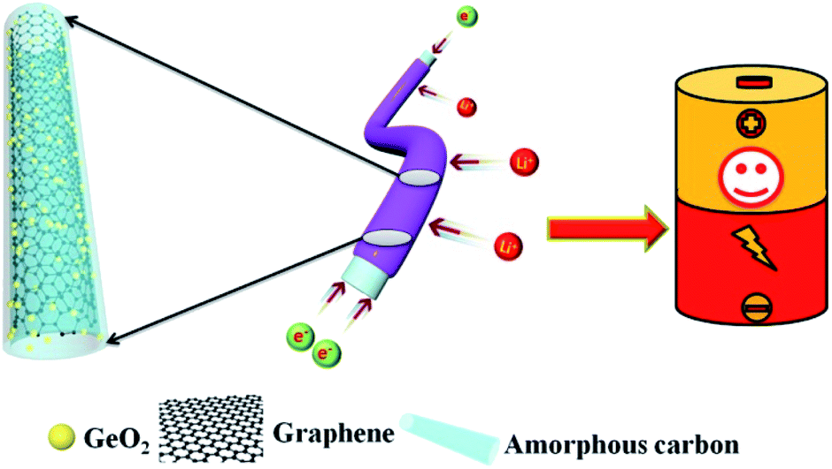 | ||
| Scheme 1 Schematic illustration of GeO2/nanocable. | ||
Scanning electron microscopy (SEM) images show as-prepared products possess a 1D fiber-like morphology with a typical length on the order of 10–100 μm and an average diameter of ∼300 nm (Fig. 1a and b). The microstructure of the GeO2/nanocable was further investigated by transmission electron microscopy (TEM) (Fig. 1c–e) accompanied by selective area electron diffraction (SAED). As shown in Fig. 1c, the graphene “core” was clearly embedded within an amorphous carbon “shell”, judging by the distinct contrasts in the TEM images. The “shell” has a thickness of ∼100 nm while the “core” has a diameter of approximately 200 nm. Graphene enhanced the flexibility of the GeO2/nanocable. As depicts in Fig. S1,† after bending, the structure of GeO2/nanocable could remain intact while the GeO2/CNF collapsed. The formation mechanism of the GeO2/nanocable prepared by a single-hole needle should be the conductivity difference between graphene and the electrospinning solution (PAN dissolved in DMF). Driven by a high voltage electrostatic force, graphene nanosheets with good electrical conductivity may join together to form the nanocable's “core”, and the corresponding PAN solution forms the amorphous carbon “shell”. As shown in Fig. 1d and e, higher-magnification images show that many nanoparticles of diameter < 20 nm were attached to the “core”. The inset of Fig. 1d shows the SAED rings of GeO2, where the inner and outer diffraction rings correspond to the diffractions of the (100) and (101) planes, respectively.31 Therefore, the above nanoparticles may be reasonably attributed to GeO2 primary nanoparticles. Fig. 1f shows the dark field scanning transmission electron microscopy (STEM) image of GeO2/nanocable, where the bright contrast further confirms the nanocable structure of the product. Energy-dispersive spectroscopy (EDS) elemental mapping analysis was employed to investigate the elemental distribution of the GeO2/nanocable. As shown in Fig. 1g–i, the C, O, and Ge elemental maps match well with the STEM image (Fig. 1f). In Fig. 1g, as is consistent with the TEM image, the C elemental map is consisted of light red “shell” and dark red “core”. Combined with the above TEM analysis, the light red “shell” is recognized as amorphous carbon, because the texture of the amorphous carbon is the same as that obtained without graphene (as depicted in Fig. S2†). The dark red “core” is supposed as graphene based on the fact that GO is the only possible carbon source except PAN. From Fig. 1h–i, Ge and O are not uniformly distributed over the entire area of the nanocable but are concentrated in the “core” area. Because when the GO solution was mixed with Ge4+, Ge4+ would be selectively bonded with the oxygenated groups by electrostatic forces due to GO nanosheets contained epoxyl and hydroxyl groups on the basal planes and carboxylic acid groups.32 This is another evidence that support graphene is the “core” of the nanocable.
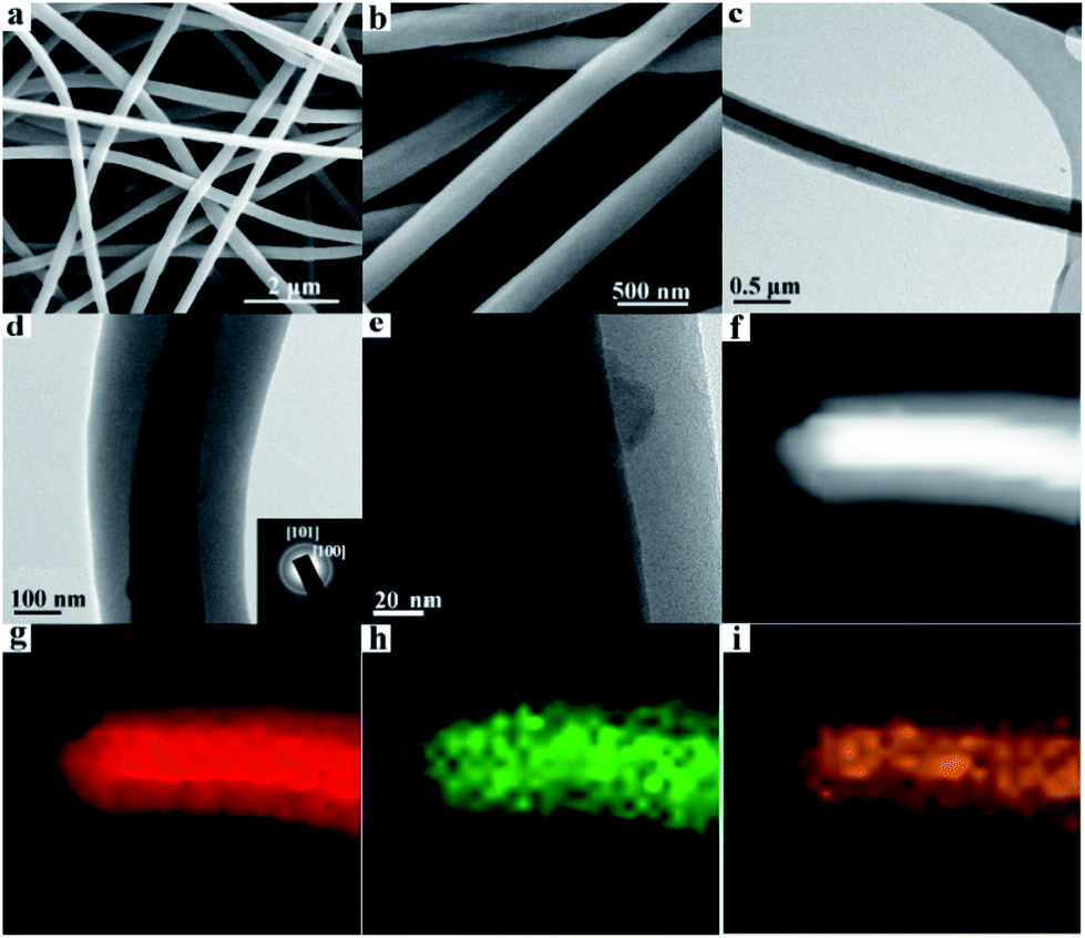 | ||
| Fig. 1 (a and b) SEM images of GeO2/nanocable at low and high magnifications. (c and d) TEM and (e) HRTEM images of GeO2/nanocable, inset of (d) is the corresponding SAED patterns; (f) dark field STEM image and (g–i) EDS-elemental mapping images of a single GeO2/nanocable (images g, h and i represent C, O and Ge elements, respectively). | ||
X-ray photoelectron spectroscopy (XPS) curves of the GeO2/nanocable shown in Fig. 2a indicate the existence of Ge, C, and O elements. The corresponding high-resolution spectrum shows that there is a sharp XPS peak of Ge 3d at a binding energy at 32.8 eV, confirming the presence of Ge4+ in the GeO2/nanocable (Fig. 2b).11,33 Moreover, a high resolution O 1s peak is displayed in Fig. 2c at 531.8 eV, suggesting that oxygen exists in the O2− oxidation state.34,35 The high-resolution C 1s spectrum shows one primary and one shoulder peak centered at 284.7 and 286.7 eV corresponding to C–C and C–N, respectively (Fig. 2d).36
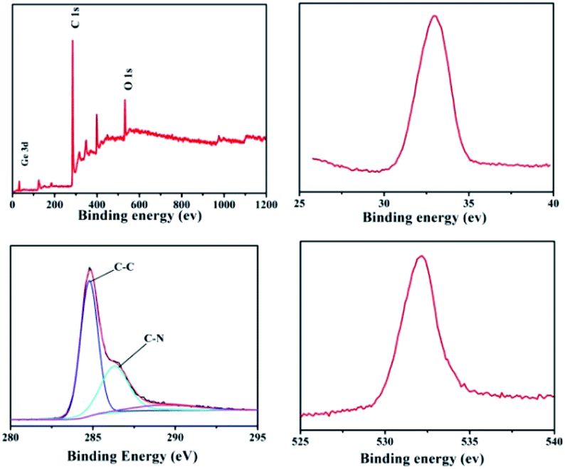 | ||
| Fig. 2 XPS spectra of GeO2/nanocable: (a) the full XPS spectrum of the GeO2/nanocable; (b–d) high-resolution spectra Ge 3d, C 1s and O 1s, respectively. | ||
Fig. 3a shows the X-ray diffraction (XRD) patterns of the GeO2/nanocable. The sharp diffraction peaks centered at 20.5°, 26.3°, and 38.2° corresponded to the (100), (101), and (102) planes of the crystalline GeO2, respectively, thereby confirming the presence of GeO2.37 No carbon and graphene-related peaks were observed because of their relatively low crystallinity compared with that of GeO2.12 Fig. 3b shows the Raman spectra of commercial GeO2 and GeO2/nanocable. The sharp peak at 443 cm−1 corresponds to the characteristic peak of GeO2 (red). The absence of GeO2 peak in GeO2/nanocable (green) implies most of GeO2 was beneath the amorphous carbon “shell” and its content in the “shell” was very low, this result is consistent with the above EDS mapping analysis. A 2D band, which is the characteristic band of graphene can be observed at 2600–3000 cm−1 in the Raman spectra of GeO2/nanocable further confirms the existence of graphene.38 Two sharp peaks at 1332 and 1590 cm−1 are present in the GeO2/nanocable spectrum, which could be assigned to the defect (D) and graphitized (G) bands of carbon, respectively.39 The intensity ratio of the D band is obviously higher than that of the G band, which indicates that higher amounts of disordered carbon were formed with numerous defects in the amorphous carbon layer (Raman spectra of nanomaterials primarily yield surface information). Amorphous carbon has two effects on the rate performance of LIBs. On the one hand, disordered carbon would enhance the Li ion diffusion kinetics, thus improving the high-rate performance during charge/discharge cycles of the LIBs.40,41 On the other hand, excessive amorphous carbon (or thick coating layer) would reduce the electronic conductivity of the electrode, which is harmful to its rate performance.42 In the GeO2/nanocable, the graphene “core” promises the good electrical conductivity while the amorphous carbon “shell” guarantees the fast Li ions diffusion, thus the high power density of the anode material could be anticipated.
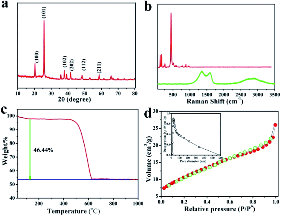 | ||
| Fig. 3 (a) XRD pattern of GeO2/nanocable, (b) Raman spectra of GeO2/nanocable (green line) and commercial GeO2 powder (red line), (c) TG curve of GeO2/nanocable in oxygen atmosphere, (d) nitrogen adsorption and desorption isotherms of GeO2/nanocable, inset image is the corresponding pore size distribution plots. | ||
The GeO2 content in the GeO2/nanocable was determined by thermal gravimetric analysis (TGA). In the GeO2/nanocable, the weight ratio of GeO2 is 53.56 wt%, and the weight ratio of graphene and amorphous carbon is 46.44 wt% based on the weight loss on carbon combustion and the fact that GeO2 is stable in air. The weight loss that commences at 500–600 °C could be attributed to the graphene and the amorphous carbon combustion reaction. The specific surface area of the GeO2/nanocable, which is calculated using Brunauer–Emmett–Teller (BET) measurements, is 28.3 m2 g−1. The nitrogen adsorption–desorption isotherm exhibits a typical IV-type isotherm with an H3 type hysteresis loop (Fig. 3d).12 These surface area values indicate that the GeO2/nanocable possesses a porous nanostructure, which may be caused by the amorphous carbon layer. According to the above structural characterization, we believe that the rationally designed GeO2/nanocable could be presented an ideal anode material for high-performance LIBs.
To systematically study the electrochemical performance of the GeO2/nanocable, various electrochemical tests including cyclic voltammetry (CV), electrochemical impedance spectroscopy (EIS) and galvanostatic charge/discharge were performed. GeO2/CNF was also tested for comparison. Initially, the Li storage mechanism of the GeO2/nanocable was investigated by using CV and the corresponding CV curves are shown in Fig. 4a. The sample was tested at a scan rate of 0.2 mV s−1 from 0.0 to 3.0 V vs. Li+/Li. During the first cathodic scan, the peak at around 0.65 V arose from the decomposition of the electrolyte, the irreversible reaction between electrode and electrolyte to form a stable solid electrolyte interface (SEI) layer, and the irreversible reaction of Li and GeO2 to form Li2O (GeO2 + 4Li+ → Ge + 2Li2O).8,14,43 The sharp cathodic peak below 0.30 V corresponded to a series of LixGe phases.13,43 During the anodic scan, the peak at around 0.35 V was caused by the dealloying reaction of LixGe alloys.20,44,45 The broad peak located at approximately 1.15 V arose from the reoxidation of Ge to GeO2, thus result in the partial reversibility of the GeO2 conversion reaction.14,15 After the first cycle, the CV curves of the GeO2/nanocable overlapped well, suggesting good stability and reversibility of the GeO2/nanocable electrode for Li ions insertion and extraction.
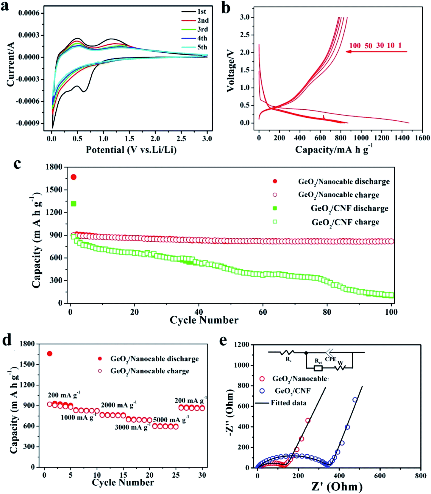 | ||
| Fig. 4 (a) CV curves of the GeO2/nanocable in the voltage window 0.0–3.0 V at a scan rate of 0.1 mV s−1. (b) Charge–discharge curves of GeO2/nanocable at the 1st, 10th, 30th, 50th and 100th cycles (current: 200 mA g−1). (c) Comparison of the cycling performance of GeO2/nanocable and GeO2/CNF 200 mA g−1. (d) Rate performance the GeO2/nanocable at different current densities. (e) EIS spectra of GeO2/nanocable and GeO2/CNF electrodes. | ||
The galvanostatic charge–discharge profiles of the GeO2/nanocable electrodes were recorded in the voltage window of 0.0–3.0 V versus Li/Li+ at a current rate of 200 mA h g−1 over 100 cycles (Fig. 4b). In the first discharge profile, a voltage plateau at approximately 0.4 V and a subsequent long continuous voltage drop down to 0.0 V could be observed, which match well with the CV data and are indicative of Li-alloying reactions. The GeO2/nanocable electrode displays an initial discharge/charge capacity of 1470/900 mA h g−1; the high initial irreversible capacity is related to the formation of the SEI layer, electrolyte decomposition and the irreversible reaction of GeO2 with Li. After the first cycle, the reversibility of the GeO2/nanocable significantly improved and the coulombic efficiency increased up to 97% after the second cycle. Fig. 4c compares the cycling performance of the GeO2/nanocable and the GeO2/CNF electrodes at a current density of 200 mA h g−1. For the GeO2/nanocable electrode, the capacity stabilized at above 819 mA h g−1 after 100 cycles. The capacity loss between the 1st and 100th cycles was only 9%, thus showing the superior cyclability of GeO2/nanocable (calculated based on the reversible charge capacities). In contrast, the declining capacity plots of the GeO2/CNF electrode indicates its poor cycling performance. In fact, the GeO2/CNF electrode showed a capacity retention of only 12.5% with a final reversible capacity of 110 mA h g−1. The excellent structural strength and flexibility of graphene led to good cycling stability of the GeO2/nanocable electrode, and this assumption could be further verified by the SEM images that obtained at the end of cycles (see ESI, Fig. S3†). Fig. S3† compares the SEM images of both electrodes after 100 cycles. From these images, it is clear that most of the GeO2/nanocables maintain their original 1D structures, while GeO2/CNF shows obvious fracture phenomena.
As shown in Fig. 4d, the rate capacities of GeO2/nanocable electrodes were also tested. The performed current increased over every 5 cycles in step from 200 mA h g−1 to 5000 mA h g−1 and back to 200 mA h g−1 at the last 5 cycles. At the currents of 200, 1000, 2000, 3000 and 5000 mA h g−1, the corresponding reversible charge capacities were approximately 890, 825, 760, 690 and 595 mA h g−1, respectively. When the specific current was returned back to 200 mA h g−1, the capacity rose to 865 mA h g−1, which is very close to the initial charge capacity. These results demonstrate that the GeO2/nanocable electrode exhibits good tolerance to variable charge/discharge currents, which is an important characteristic required for high-power applications. Since the rate capability is dominated by the kinetics of lithium-ion diffusion and electronic conductivity, the better electrochemical performance of the GeO2/nanocable electrode was further verified using EIS measurements with a GeO2/CNF electrode for comparison. As shown in Fig. 4e, the EIS plots consisted of a semicircle at medium to high frequency and a straight line at low frequency. The inset of Fig. 4e shows the Randles equivalent electrical circuit model of both electrodes, it can be observed that the experimental data could be well fitted using the equivalent circuit model. As is shown, the GeO2/nanocable electrode shows a considerably lower charge-transfer resistance (135 Ω) compared to that of the GeO2/CNF electrode (331 Ω) (Fig. 4e and ESI Table S1†), indicating a faster charge-transfer reaction for the GeO2/nanocable anode.46 This would lead to a good rate capability of the GeO2/nanocable electrode.
Conclusions
A novel GeO2/nanocable electrode material was successfully synthesized by a facile electrospinning method, in which graphene act as the “core” and amorphous carbon as the “shell”, and GeO2 nanoparticles were encapsulated in the nanocable. As anode material for LIBs, the graphene “core” promises the good electrical conductivity while the amorphous carbon “shell” guarantees the fast Li ions diffusion. The graphene “core” could effectively alleviate volume expansion, and maintain structural stability of the GeO2/nanocable electrodes. Therefore, the GeO2/nanocable exhibited satisfactory Li storage performance including high reversible capacity (900 mA h g−1), excellent cycling performance (91% after 100 cycles) and rate performance (595 mA h g−1 at 5000 mA g−1). Our work demonstrates a successful case for the preparation of GeO2/nanocable anode materials for advanced LIBs, and the proposed preparation strategy could be extended to boost other metal or oxide anodes.Conflicts of interest
The authors declare no competing financial interest.Acknowledgements
This study was supported by The National Science Foundation of China (U1804138), the Science Foundation of Henan province (162300410209), and the Special Key Research Program of Henan Province (182102210488).Notes and references
- Z. Zhu, Y. Tang, Z. Lv, J. Wei, Y. Zhang, R. Wang, W. Zhang, H. Xia, M. Ge and X. Chen, Angew. Chem., Int. Ed., 2018, 57, 3656–3660 CrossRef CAS PubMed.
- G. Cui, L. Gu, L. Zhi, N. Kaskhedikar, P. A. van Aken, K. Müllen and J. Maier, Adv. Mater., 2008, 20, 3079–3083 CrossRef CAS.
- W. Wei, Z. Wang, Z. Liu, Y. Liu, L. He, D. Chen, A. Umar, L. Guo and J. Li, J. Power Sources, 2013, 238, 376–387 CrossRef CAS.
- Z. Wen, Q. Wang, Q. Zhang and J. Li, Adv. Funct. Mater., 2007, 17, 2772–2778 CrossRef CAS.
- H. Wang, H. Feng and J. Li, Small, 2014, 10, 2165–2181 CrossRef CAS PubMed.
- D. Lv, M. L. Gordin, R. Yi, T. Xu, J. Song, Y.-B. Jiang, D. Choi and D. Wang, Adv. Funct. Mater., 2014, 24, 1059–1066 CrossRef CAS.
- Y. Tang, Y. Zhang, W. Li, B. Ma and X. Chen, Chem. Soc. Rev., 2015, 44, 5926–5940 RSC.
- J. s. S. Peña, I. Sandu, O. Joubert, F. S. n. Pascual, C. O. Areán and T. Brousse, Electrochem. Solid-State Lett., 2004, 7, A278 CrossRef.
- A. Jahel, A. Darwiche, C. Matei Ghimbeu, C. Vix-Guterl and L. Monconduit, J. Power Sources, 2014, 269, 755–759 CrossRef CAS.
- W. Wei and L. Guo, Part. Part. Syst. Charact., 2013, 30, 658–661 CrossRef CAS.
- W. Wei, F. Jia, P. Qu, Z. Huang, H. Wang and L. Guo, Nanoscale, 2017, 9, 3961–3968 RSC.
- H. Jia, R. Kloepsch, X. He, J. P. Badillo, M. Winter and T. Placke, J. Mater. Chem. A, 2014, 2, 17545–17550 RSC.
- D. T. Ngo, R. S. Kalubarme, H. T. Le, C. N. Park and C. J. Park, Nanoscale, 2015, 7, 2552–2560 RSC.
- S. Yan, H. Song, S. Lin, H. Wu, Y. Shi and J. Yao, Adv. Funct. Mater., 2019, 29, 1807946 CrossRef.
- S. Zhang, Y. Zheng, X. Huang, J. Hong, B. Cao, J. Hao, Q. Fan, T. Zhou and Z. Guo, Adv. Energy Mater., 2019, 9, 1900081 CrossRef.
- W. Wei, J. Xu, M. Xu, S. Zhang and L. Guo, Sci. China: Chem., 2018, 61, 515–525 CrossRef CAS.
- X. Zhong, H. Huan, X. Liu and Y. Yu, Nano Res., 2018, 11, 3702–3709 CrossRef CAS.
- Y. Chen, C. Yan and O. G. Schmidt, Adv. Energy Mater., 2013, 3, 1269–1274 CrossRef CAS.
- D. Liu, Z. J. Liu, X. Li, W. Xie, Q. Wang, Q. Liu, Y. Fu and D. He, Small, 2017, 13, 1702000 CrossRef PubMed.
- S. H. Choi, K. Y. Jung and Y. C. Kang, ACS Appl. Mater. Interfaces, 2015, 7, 13952–13959 CrossRef CAS PubMed.
- X. Wei, W. Li, L. Zeng and Y. Yu, Part. Part. Syst. Charact., 2016, 33, 524–530 CrossRef CAS.
- F. Jia, L. Song, W. Wei, P. Qu and M. Xu, New J. Chem., 2015, 39, 689–695 RSC.
- J. Hu, C. Ouyang, S. A. Yang and H. Y. Yang, Nanoscale Horiz., 2019, 4, 457–463 RSC.
- D. J. Xue, S. Xin, Y. Yan, K. C. Jiang, Y. X. Yin, Y. G. Guo and L. J. Wan, J. Am. Chem. Soc., 2012, 134, 2512–2515 CrossRef CAS PubMed.
- S. Heuser, N. Yang, F. Hof, A. Schulte, H. Schonherr and X. Jiang, Small, 2018, 14, e1801857 CrossRef PubMed.
- Y. Zhang, P. Yan, Q. Wan and N. Yang, Carbon, 2018, 134, 540–547 CrossRef CAS.
- X. Ma, Y. Zhou, M. Chen and L. Wu, Small, 2017, 13, 1700403 CrossRef PubMed.
- W. Li, Z. Yang, J. Cheng, X. Zhong, L. Gu and Y. Yu, Nanoscale, 2014, 6, 4532–4537 RSC.
- Y. W. Lee, D. M. Kim, S. J. Kim, M. C. Kim, H. S. Choe, K. H. Lee, J. I. Sohn, S. N. Cha, J. M. Kim and K. W. Park, ACS Appl. Mater. Interfaces, 2016, 8, 7022–7029 CrossRef CAS PubMed.
- F. Pantò, Y. Fan, S. Stelitano, E. Fazio, S. Patanè, P. Frontera, P. Antonucci, N. Pinna and S. Santangelo, Adv. Funct. Mater., 2018, 28, 1800938 CrossRef.
- H. Qiu, L. Zeng, T. Lan, X. Ding and M. Wei, J. Mater. Chem. A, 2015, 3, 1619–1623 RSC.
- S. Stankovich, D. A. Dikin, G. H. B. Dommett, K. M. Kohlhaas, E. J. Zimney, E. A. Stach, R. D. Piner, S. T. Nguyen and R. S. Ruoff, Nature, 2006, 442, 282–286 CrossRef CAS PubMed.
- K. Prabhakaran, F. Maeda, Y. Watanabe and T. Ogino, Appl. Phys. Lett., 2000, 76, 2244–2246 CrossRef CAS.
- M. Oku, K. Wagatsuma and S. Kohiki, Phys. Chem. Chem. Phys., 1999, 1, 5327–5331 RSC.
- N. Shi, X. Li, T. Fan, H. Zhou, J. Ding, D. Zhang and H. Zhu, Energy Environ. Sci., 2011, 4, 172–180 RSC.
- X. Li, H. Wang, J. T. Robinson, H. Sanchez, G. Diankov and H. Dai, J. Am. Chem. Soc., 2009, 131, 15939–15944 CrossRef CAS PubMed.
- S. Sarkar, R. Borah, A. L. Santhosha, R. Dhanya, C. Narayana, A. J. Bhattacharyya and S. C. Peter, J. Power Sources, 2016, 306, 791–800 CrossRef CAS.
- J. Liang, W. Wei, D. Zhong, Q. Yang, L. Li and L. Guo, ACS Appl. Mater. Interfaces, 2012, 4, 454–459 CrossRef CAS PubMed.
- S. Fang, L. Shen, H. Zheng and X. Zhang, J. Mater. Chem. A, 2015, 3, 1498–1503 RSC.
- A. D. Roberts, X. Li and H. Zhang, Chem. Soc. Rev., 2014, 43, 4341–4356 RSC.
- M. Li, D. Zhou, W.-L. Song, X. Li and L.-Z. Fan, J. Mater. Chem. A, 2015, 3, 19907–19912 RSC.
- L. Liu, T. Song, H. Han, H. Park, J. Xiang, Z. Liu, Y. Feng and U. Paik, J. Mater. Chem. A, 2015, 3, 17713–17720 RSC.
- D. T. Ngo, H. T. T. Le, R. S. Kalubarme, J.-Y. Lee, C.-N. Park and C.-J. Park, J. Mater. Chem. A, 2015, 3, 21722–21732 RSC.
- R. Xu, S. Wu, Y. Du and Z. Zhang, Chem. Eng. J., 2016, 296, 349–355 CrossRef CAS.
- N. Sun, C.-l. Peng, J.-c. Zheng, Z.-j. He, H. Tong, L.-b. Tang, C.-s. An and B. Xiao, Powder Technol., 2018, 338, 211–219 CrossRef CAS.
- L. Zhao, H. Chen, Y. Wang, H. Che, P. Gunawan, Z. Zhong, H. Li and F. Su, Chem. Mater., 2012, 24, 1136–1142 CrossRef CAS.
Footnote |
| † Electronic supplementary information (ESI) available: Experimental section, flexibility comparison between GeO2@nanocable and GeO2@CNF, TEM image of the prepared GeO2@CNF sample, SEM images of GeO2@nanocable & GeO2@CNF electrodes after cycling, and Nyquist parameters of GeO2@nanocable and GeO2@CNF. See DOI: 10.1039/d0ra00720j |
| This journal is © The Royal Society of Chemistry 2020 |