
 Open Access Article
 This Open Access Article is licensed under a
 Creative Commons Attribution 3.0 Unported Licence
Modular construction of size-selected multiple-core Pt–TiO2 nanoclusters for electro-catalysis
Caroline E.
Blackmore
ab,
Neil V.
Rees
b and
Richard E.
Palmer
*a
aNanoscale Physics Research Laboratory, School of Physics and Astronomy, University of Birmingham, Birmingham, B15 2TT, UK. E-mail: R.E.Palmer@bham.ac.uk
bSchool of Chemical Engineering, University of Birmingham, Birmingham, B15 2TT, UK
First published on 4th March 2015
Abstract
Size-selected binary platinum–titanium dioxide (Pt–TiO2) clusters have been generated using a magnetron sputtering gas condensation cluster source and imaged using a Scanning Transmission Electron Microscope (STEM) in High Angle Annular Dark Field (HAADF) mode. The core–shell clusters exhibit a Pt core of preferred size 30 ± 6 atoms (1 nm), embedded in an oxidised Ti shell, independent of the overall cluster size (varied between 2 nm and 5 nm). Smaller clusters, with mass ≤50![[thin space (1/6-em)]](https://www.rsc.org/images/entities/char_2009.gif) 000 Daltons, show a single Pt core while larger clusters, ≥55000 Daltons, feature multiple Pt cores, either isolated or aggregated within the TiO2 shell. These clusters may have applications in solar hydrogen production; preliminary work indicates catalytic active in the hydrogen evolution reaction.
000 Daltons, show a single Pt core while larger clusters, ≥55000 Daltons, feature multiple Pt cores, either isolated or aggregated within the TiO2 shell. These clusters may have applications in solar hydrogen production; preliminary work indicates catalytic active in the hydrogen evolution reaction.
Introduction
Platinum nanoparticles play a significant role in catalysis, particularly within the energy sector where there is an expanding need for green technology.1 Fuel cells offer a method of environmentally friendly transportation, but their scope is limited by the cost and scarcity of the platinum upon which they depend.2–5 Through nano-structuring and partial replacement of platinum, the economics of fuel cells (and of the production of hydrogen) can potentially be improved.6 The exploitation of nano-alloy clusters7 is one possible route towards less Pt-rich catalysts.Platinum–titanium (Pt–Ti) nanoparticles have been predicted theoretically to offer better reaction kinetics and lower poisoning levels than pure platinum nanoparticles within Polymer Electrolyte Membrane (PEM) fuel cells.8,9 The target is a core of Ti atoms within a shell, one to two atoms thick, of Pt atoms. By contrast, for solar hydrogen production (water splitting) TiO2 shell nanoparticles may be preferred.10,11 Chemical synthesis of Pt–TiO2 core–shell clusters has been reported.12–14 Amongst research into TiO2 photo catalysis,15,16ref. 17 shows that the addition of Pt improves the efficiency of visible light absorption, thus improving the water splitting capacity.
The aim of this work is to research the multi-core structure of Pt core–TiO2 shell clusters, which, ultimately may have applications within solar hydrogen production. Within this paper we report the production of size-selected Pt core–TiO2 shell clusters by gas-phase cluster beam methods. This proof of concept work focuses on fine mass control of the clusters, producing enough clusters for electrochemical characterization. The clusters are deposited and imaged on holey carbon supports by aberration-corrected STEM in HAADF mode, established as a powerful probe of the atomic structure of size-selected clusters.18–22 Small clusters display a single Pt core, whilst larger clusters exhibit multiple Pt cores; in both cases the shell is TiO2. Multiple core nanoclusters have previously been produced via chemical synthesis23–25 and, recently, by magnetron sputtering-based techniques.26 These have been predominantly targeted towards biomedical applications, exploiting their magnetic properties. We identify a preferred core size of 30 ± 6 Pt atoms, which seems to represent a critical nucleus for the condensation of Ti atoms in the source. Larger clusters are generated by the modular assembly of this ‘simple’ core–shell cluster by gas-phase aggregation.
Experimental methods
Pt–Ti clusters were produced with a magnetron sputtering gas condensation cluster beam source27,28 prior to size selection with a lateral time-of-flight mass selector.29 Argon gas is used to create an DC plasma that sputters Pt and Ti atoms from a binary target (99.95% pure), which has a mass ratio of 25% Pt to 75% Ti (approximately 1 in 13 atoms are Pt). The atoms are condensed into clusters in a mixture of argon and helium gas, cooled by liquid nitrogen prior to size selection and deposited on to a holey carbon TEM film supported on copper grids at cluster ion impact energy of 500 eV. Previous work by Yin et al.30,31 showed the formation of both gold core–copper shell and copper core–gold shell nano-clusters was possible through the tuning of the cluster source parameters. However in our case only Pt core–Ti shell clusters have been successfully produced to date. The cluster masses chosen ranged from 20000 Daltons (Da) to 120000 Da, thus total diameters ranged between approximately 2 nm and 5 nm. The cluster shell oxidises from Ti to TiO2 (see below) while being transferred, in air, from the cluster source to STEM.
To analyse the STEM images a macro was written in FIJI. The macro works by taking the value of each pixel and averaging it with the value of its nearest four neighbours. Regarding the background the median value from the image is taken as a good estimation of the background intensity, thus the criteria for thresholding is a comparison of this median and the corrected pixel value. This method reduces the amount of single pixel noise (which is the same intensity as the Pt atoms) filtered as Pt. The FIJI built in analyse particles function is then used to identify and number these areas as cores.
STEM results and analysis
The imaging of the clusters has been performed using a 200 kV JEOL 2100F STEM equipped with a spherical aberration (Cs) corrector (CEOS). Fig. 1 shows Pt–TiO2 nanoclusters of four different masses at two different magnification levels. Correlation of the selected cluster masses with the measured volumes of the cluster shells confirms the stoichiometry of the shell is TiO2. The largest clusters of mass 120 kDa, (Fig. 1A and E), show multiple cores of Pt (yellow) within a shell of TiO2 (pink) on a carbon only background (purple). By contrast the smallest clusters of mass 30 kDa, (Fig. 1D and H), show a single Pt core with a shell of TiO2. The intermediate sizes show that the number of cores increases as the overall size of the clusters increase. For 60 kDa the clusters typically exhibit either, a single large core or two smaller cores.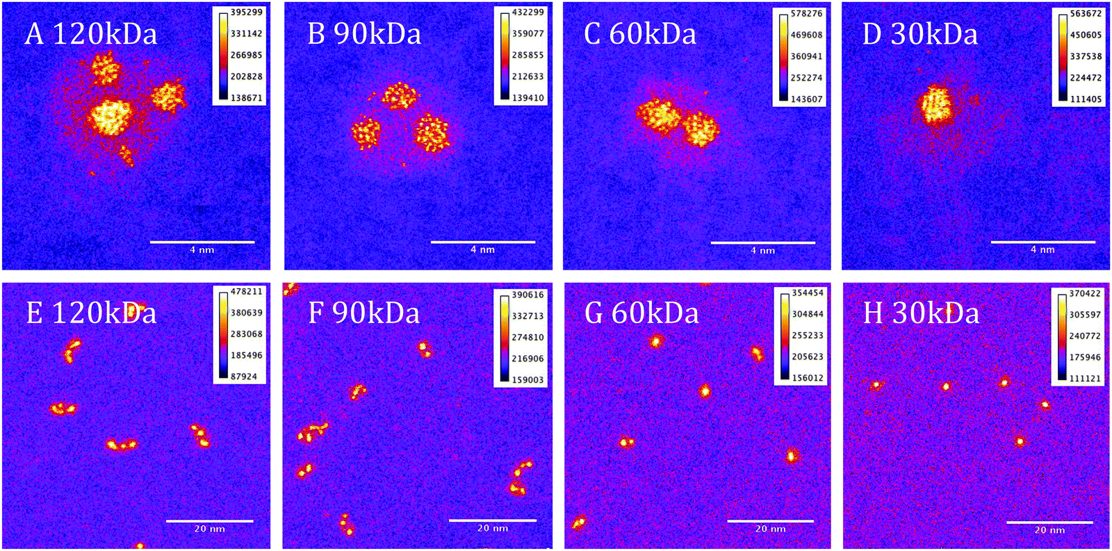 | ||
| Fig. 1 STEM images of Pt–TiO2 clusters. Larger clusters (A and E) are formed of multiple Pt (yellow) cores within a TiO2 (pink) shell on a carbon (purple) substrate. Small clusters (D and H) show a single Pt core within a TiO2 shell. | ||
The growth mode of the clusters, as deduced from the STEM data, is initial Pt condensation followed by Ti condensation onto the Pt cores. The multiple core structure of the clusters shows that smaller clusters of Pt–Ti, of mass ∼30 kDa are aggregating in the source to form the larger clusters, i.e., what we have is a kind of modular construction. From the images it can be seen that some of the Pt cores in the larger clusters have a similar size to those in the small “building block” clusters. Larger cores, we also observed, are presumably formed by aggregation of the cores during the coalescence of the “modules”.
To illustrate our method of quantitative analysis of the STEM images Fig. 2A and C show one nanocluster (60 kDa) before and after thresholding, as described earlier. Discarding particles less than 0.25 nm in diameter as noise and single atoms, the area within the particle identified in Fig. 2C is used to calculate the radius of an equivalent circle, and thence the volume of a Pt sphere. Using the bulk density of Pt, the sphere's volume is then converted to the number of Pt atoms in each core. From Fig. 2B and D it can be seen that for a two-cored cluster our macro identifies two particles as expected, and outputs the Pt core nuclearity for each. This analysis has been performed on a minimum of 50 clusters for each mass of cluster deposited.
 | ||
| Fig. 2 Images of 60 kDa clusters before and after thresholding. | ||
The method of analysis employed is very reproducible and fast, but of course errors can be introduced. The automatic thresholding can lead to some Pt atoms being missed or TiO2 atoms being included within the threshold. To minimise such errors we checked all images manually, adjusting as necessary. Assuming that the cores are spherical leads to an error that cannot be corrected for. Using the bulk density of Pt to calculate the number of Pt atoms within the calculated volume will also lead to an error, as the atomic structure of the embedded is not resolved sufficiently to correct for the bond lengths. To reflect the accumulated errors, the histogram bar widths in Fig. 3–5 have been chosen to be 12 atoms so that the number of Pt atoms is quoted as the centre of the bar ±6 atoms. Thus the relationships between the number of Pt atoms in different cores are sound, but the precision in the absolute numbers of Pt atoms might be improved according to the analysis method deployed.
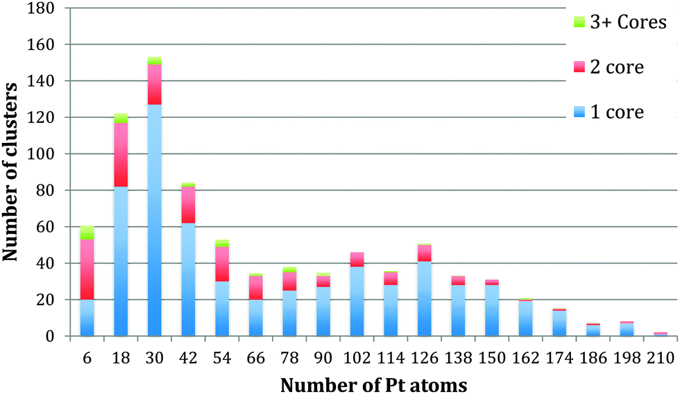 | ||
| Fig. 3 Histogram to display the number of cores within each cluster with relation to each core size. | ||
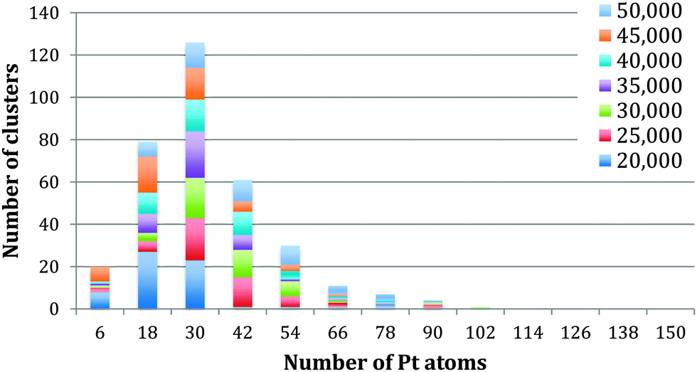 | ||
| Fig. 4 Analysis of the number of Pt atoms within the single cored clusters between 20 kDa and 50 kDa. | ||
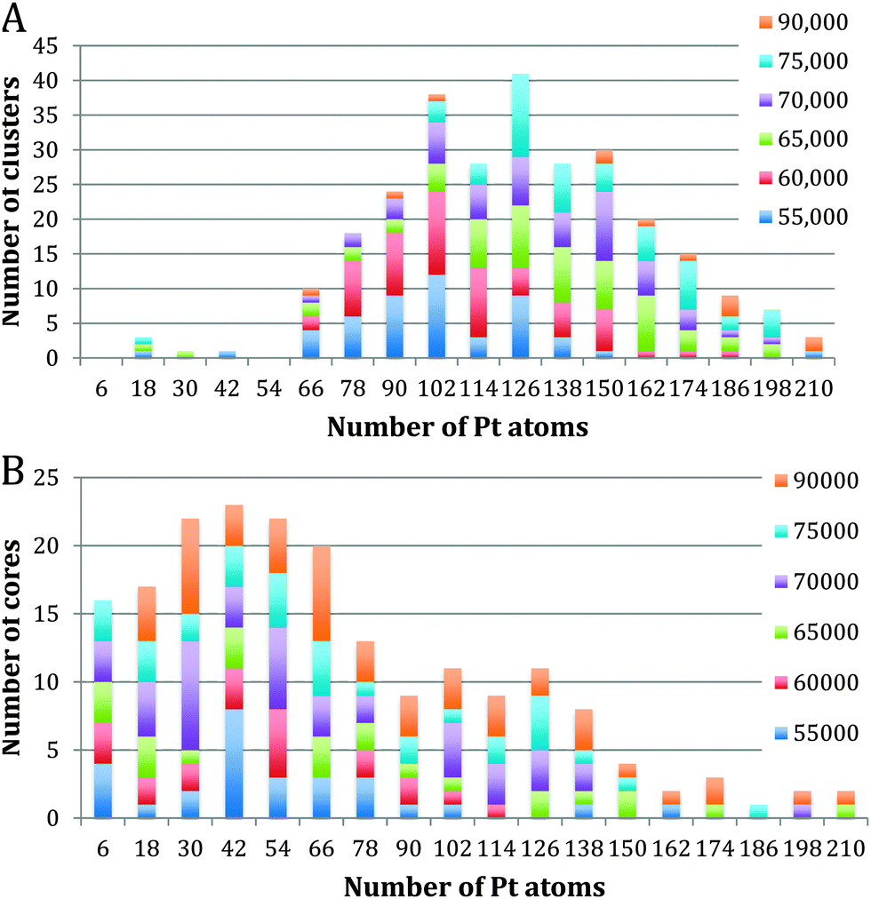 | ||
| Fig. 5 Analysis of single vs. dual core clusters: (A) shows the number of Pt atoms within the single cored clusters between 55 kDa and 90 kDa, and (B) the number of Pt atoms within two cored clusters. | ||
Repeated imaging with STEM of clusters has shown the clusters to be stable over a period of months.
Discussion and STEM results
Fig. 3 shows the size distribution of the Pt cores integrated over all Pt–Ti core–shell clusters studied, ranging from 20 kDa up to 75 kDa (5 kDa step size). The core size is given as the number of Pt atoms in the core and the colour code denotes clusters containing one, two or three and more cores. It can be seen that the majority of clusters have a single core, although the fraction of multiple-core clusters is greater for smaller core sizes. Notably there is a distinctive peak in Pt core size centred at 30 ± 6 Pt atoms, with a second broad peak between 102 and 126 Pt atoms. The peak centred at 30 ± 6 atoms corresponds to the small cores seen in the STEM images. The second broad peak is attributed to multiple small cores fusing together during the aggregation of single core clusters during cluster growth. Together they give the graph a characteristic bimodal distribution.To further investigate the phenomenon of a preferred Pt core size, Fig. 4 shows the size distribution of the Pt cores from clusters with only one core and overall cluster mass less than 50 kDa. 92% of the clusters up to 50 kDa were found to have single cores. These are the “modules” from which we believe larger clusters are assembled in the gas condensation growth process. The figure shows a single peak at 30 ± 6 Pt atoms for the nuclearity of the core. Within this range of cluster mass there is no change in average core size as the deposited cluster size varies. Instead the data support the idea that a preferred size of Pt core functions as a critical nucleus upon which Ti atoms are condensed. Theoretical work on the structure of small Pt particles predicts that for Pt clusters between 24 and 38 atoms, cubic isomers have the lowest energy, with 27 atoms being especially stable.32
Fig. 5A and B show Pt core-size for Pt–Ti clusters of mass larger than 55 kDa. They have been split into single core and two core plots. 64% of the clusters above 55 kDa have a single core, while 25% have two cores. The remaining 11% contain 3 or more cores. The single core graph shows a peak at 126 ± 6 Pt atoms, with very few cores containing less than 60 Pt atoms. This observation is again consistent with the picture in which single cores of a size ∼30 Pt atoms coalesce during cluster aggregation during the growth process. This interpretation is confirmed by looking at the double core data, Fig. 5B which does show a peak near 30 Pt atoms, specifically, at 42 ± 6 Pt atoms; we believe these are the cores that have not coalesced during cluster aggregation.
It is tempting to speculate that the probability that two Pt cores, in two Pt–Ti core–shell clusters which aggregate during gas phase growth, coalesce into a single larger core may depend on the relative location of the Pt cores with respect to the edge of the cluster, as well as the relative orientation of the clusters upon collision. Our data suggests that the Pt cores are often found off-centre, i.e. towards the cluster edge (e.g.Fig. 1D) but this notion needs further experimentation and analysis. Eccentric cluster cores in core–shell systems were recently predicted.33
Electrochemical results
Electrochemistry experiments were conducted using a 3 electrode arrangement with a glassy carbon (GC) working electrode, a saturated Ag/AgCl reference electrode and a bright Pt mesh counter electrode. The GC electrode was used as a substrate electrode on which to support the clusters for testing and provide a comparison for any catalytic behaviour. Potential control was via an Autolab 128N potentiostat (Metrohm, Utrecht, NL) running Nova proprietary software (version 6.1). The test solution contained 2.0 mM perchloric acid and 0.10 M sodium perchlorate (both from Sigma Aldrich) dissolved in ultrapure water of resistivity not less than 18.2 MΩ cm (Millipore).Control experiments were performed by recording cyclic voltammograms at a voltage scan rate of 25 mV s−1 using first, the bare GC electrode, and secondly the GC electrode modified with TiO2 clusters. For this work the clusters of Pt–TiO2 and pure TiO2 were soft landed on to the GC electrode. These TiO2 clusters were produced in the same manner and mass range as the Pt–TiO2 clusters. Fig. 6 clearly shows that there is no perceptible change in the position of the reduction peak, confirming that TiO2 does not behave catalytically compared to bare GC.
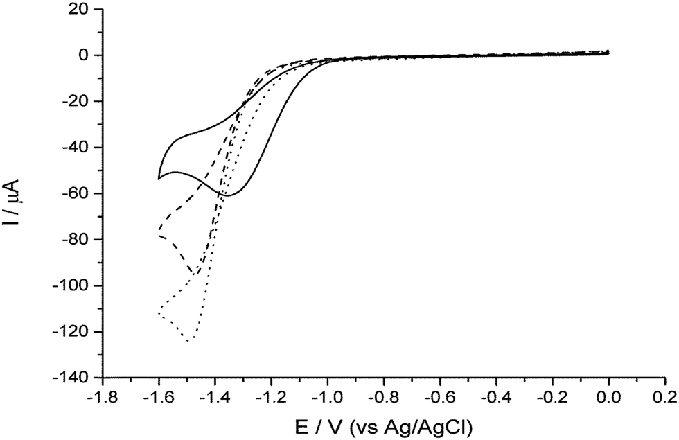 | ||
| Fig. 6 Cyclic voltammograms recorded at 25 mV s−1 (details given in text) for a solution of 2 mM HClO4 in 0.1 M NaClO4 at the following electrodes: bare GC (⋯); GC modified with ca. 5% coverage of TiO2 clusters (– – –), and GC modified with ca. 5% coverage of 2 nm PtTiO2 clusters (—). | ||
Next, experiments were conducted with the Pt–TiO2 clusters deposited onto the GC electrode. Fig. 6 shows a clear shift to lower overpotentials of both the onset of the reduction wave and the peak. In this case, we are justified in interpreting this shift as an indication of improved catalytic ability due to the low electrode coverage (ca. 5%), precluding the likelihood of the mixed mass transport regimes observed in multilayer deposit systems which also causes shifts in the wave to lower overpotentials.34
Work is currently in progress to unambiguously elucidate the kinetic parameters, since initial modelling suggests that the deposit may not be purely Case IV but is equally likely to be Case II or III,35 which is consistent with the approximate coverage of the GC substrate electrode. We note the lower magnitude of current compared to the GC control experiment is consistent with Case II or III behaviour.
Using a very approximate Case IV assumption, modelling indicates that the presence of the Pt within the Pt–TiO2 cluster has an accelerative effect on the kinetics of ca. 2 orders of magnitude. Detailed studies involving variation of coverage and simulating a Case III model are expected to confirm the rate constant and transfer coefficient.
Conclusions
We have demonstrated experimentally the production of size-selected Pt–TiO2 core–shell clusters, in which a preferred Pt core size of 30 ± 6 atoms (1 nm) is obtained. Smaller clusters, ∼2 nm, typically exhibit one core; larger clusters, ∼5 nm, feature multiple cores of the preferred size or cores which are (probably) aggregations thereof. It appears that once the Pt cores grow to the preferred size the Ti atoms condense onto the surface in an avalanche fashion forming a complete (or possibly partial) shell. We speculate that the structure and symmetry of the Ti shell regulates the coalescence of the Pt cores in the ensuing cluster–cluster collisions during gas phase growth, a modular constructive process. First electrochemistry results show promise that the clusters are electrocatalytically active.Acknowledgements
We thank EPSRC and the Centre for Hydrogen & Fuel Cell Research for financial support. The STEM instrument employed in this research was obtained through Birmingham Science City project “Creating and Characterising Next Generation Advanced Materials”, supported by Advantage West Midlands (AWM) and is part funded through the European Regional Development Fund (ERDF).References
- A. Chen and P. Holt-Hindle, Chem. Rev., 2010, 110, 3767–3804 CrossRef CAS PubMed.
- Y. Bing, H. Liu, L. Zhang, D. Ghosh and J. Zhang, Chem. Soc. Rev., 2010, 39, 2184–2202 RSC.
- K. Sasaki, H. Naohara, Y. Cai, Y. M. Choi, P. Liu, M. B. Vukmirovic, J. X. Wang and R. Adzic, Angew. Chem., 2010, 49, 8602–8607 CrossRef CAS PubMed.
- S. Litster and G. McLean, J. Power Sources, 2004, 130, 61–76 CrossRef CAS PubMed.
- B. C. Steele and A. Heinzel, Nature, 2001, 414, 345–352 CrossRef CAS PubMed.
- M. T. M. Koper, Nanoscale, 2011, 3, 2054–2073 RSC.
- R. Ferrando, J. Jellinek and R. L. Johnston, Chem. Rev., 2008, 108, 845–910 CrossRef CAS PubMed.
- P. C. Jennings, B. G. Pollet and R. L. Johnston, J. Phys. Chem. C, 2012, 116, 15241–15250 CAS.
- P. C. Jennings, B. G. Pollet and R. L. Johnston, Phys. Chem. Chem. Phys., 2012, 14, 3134 RSC.
- M. Ni, M. K. H. Leung, D. Y. C. Leung and K. Sumathy, Renewable Sustainable Energy Rev., 2007, 11, 401–425 CrossRef CAS PubMed.
- S. Srivastava, J. P. Thomas, Md. A. Rahman, M. Abd-Ellah, M. Mahapatra, D. Pradhan, N. F. Heinig and K. T. Leung, ACS Nano, 2014, 8, 11891–11898 CrossRef CAS PubMed.
- F. Matsumoto, H. Abe and S. Kinosada, J. Electrochem. Soc., 2008, 5452 Search PubMed.
- Y. Sun, J. Lu and L. Zhuang, J. Electroanal. Chem., 2013, 688, 189–195 CrossRef CAS PubMed.
- H. Abe, F. Matsumoto, L. R. Alden, S. C. Warren, H. D. Abruña and F. J. DiSalvo, J. Am. Chem. Soc., 2008, 130, 5452–5458 CrossRef CAS PubMed.
- S. K. Mohapatra and M. Misra, J. Phys. Chem. C, 2007, 111, 8677–8685 CAS.
- K. Huang, K. Sasaki, R. Adzic and Y. Xing, J. Mater. Chem., 2012, 22, 16824 RSC.
- Z. W. Wang and R. E. Palmer, Phys. Rev. Lett., 2012, 108, 245502 CrossRef CAS.
- F. B. Li and X. Z. Li, Chemosphere, 2002, 48, 1103–1111 CrossRef CAS.
- S. Bals, S. Van Aert, C. P. Romero, K. Lauwaet, M. J. Van Bael, B. Schoeters, B. Partoens, E. Yücelen, P. Lievens and G. Van Tendeloo, Nat. Commun., 2012, 3, 897 CrossRef CAS PubMed.
- Z. W. Wang and R. E. Palmer, Nano Lett., 2012, 12, 91–95 CrossRef CAS PubMed.
- S. R. Plant, L. Cao and R. E. Palmer, J. Am. Chem. Soc., 2014, 136, 7559–7562 CrossRef CAS PubMed.
- M. J. Cuddy, K. P. Arkill, Z. W. Wang, H. Komsa, A. V. Krasheninnikov and R. E. Palmer, Nanoscale, 2014, 6, 12463–12469 RSC.
- T. Yoon, H. Lee, H. Shao, S. A. Hilderbrand and R. Weissleder, Adv. Mater., 2011, 23, 4793–47937 CrossRef CAS PubMed.
- P. Hugounenq, D. Alloyeau, S. P. Clarke, M. Le, R. Bazzi, D. F. Brougham, C. Wilhelm and F. Gazeau, ACS Nano, 2012, 6, 10935–10949 Search PubMed.
- L. Gutiérrez, R. Costo, C. Grüttner, F. Westphal, N. Gehrke, D. Heinke, A. Fornara, Q. Pankhurst, C. Johansson, S. Veintemillas-Verdaguer and M. P. Morales, Dalton Trans., 2015, 44, 2943–2952 RSC.
- M. Benelmekki, M. Bohra, J. H. Kim, R. E. Diaz, J. Vernieres, P. Grammatikopoulos and M. Sowwan, Nanoscale, 2014, 6, 3532–3535 RSC.
- S. Pratontep, S. J. Carroll, C. Xirouchaki, M. Streun and R. E. Palmer, Rev. Sci. Instrum., 2005, 76, 1–8 CrossRef PubMed.
- M. Goldby, B. von Issendorff, L. Kuipers and R. E. Palmer, Rev. Sci. Instrum., 1997, 68, 3327 CrossRef PubMed.
- B. von Issendorff and R. E. Palmer, Rev. Sci. Instrum., 1999, 70, 4497–4500 CrossRef CAS PubMed.
- F. Yin, Z. W. Wang and R. E. Palmer, J. Am. Chem. Soc., 2011, 133, 10325–10327 CrossRef CAS PubMed.
- F. Yin, Z. W. Wang and R. E. Palmer, J. Exp. Nanosci., 2012, 7, 703–710 CrossRef CAS PubMed.
- V. Kumar and Y. Kawazoe, Phys. Rev. B: Condens. Matter Mater. Phys., 2008, 77, 205418 CrossRef.
- D. Bochicchio and R. Ferrando, Phys. Rev. B: Condens. Matter Mater. Phys., 2013, 87, 165435 CrossRef.
- M. J. Sims, N. V. Rees, E. J. F. Dickinson and R. G. Compton, Sens. Actuators, B, 2010, 144, 153–158 CrossRef CAS PubMed.
- T. J. Davies and R. G. Compton, J. Electroanal. Chem., 2005, 585, 63–82 CrossRef CAS PubMed.
| This journal is © the Owner Societies 2015 |