 Open Access Article
Creative Commons Attribution 3.0 Unported Licence
Highly rough copper current collector: improving adhesion property between a silicon electrode and current collector for flexible lithium-ion batteries†
Hyunkyu Jeon‡
a,
Inseong Cho‡a,
Hearin Joa,
Kyuman Kima,
Myung-Hyun Ryou *a and
Yong Min Lee
 *b
*b
aDepartment of Chemical & Biological Engineering, Hanbat National University, Daejeon 34158, Republic of Korea. E-mail: mhryou@hanbat.ac.kr; Fax: +82-42-821-1534; Tel: +82-42-821-1534
bDepartment of Energy Systems Engineering, Daegu Gyeongbuk Institute of Science and Technology (DGIST), Daegu 42988, Republic of Korea. E-mail: yongmin.lee@dgist.ac.kr; Fax: +82-53-785-6409; Tel: +82-53-785-6425
First published on 19th July 2017
Abstract
Two types of Cu foil, conventional flat Cu foil and rough Cu foil, are used to fabricate silicon (Si) electrodes for flexible and high-energy-density lithium-ion batteries (LIBs). Confocal microscopy and cross-sectional SEM images reveal the roughness of the very rough Cu foil to be approximately 3 μm, whereas the conventional flat Cu foil has a smooth surface and a roughness of less than 1 μm. This difference leads to the improvement of the interfacial adhesion strength between the Si electrode and the Cu foil from 89.7 (flat Cu foil) to 135.7 N m−1 (rough Cu foil), which is measured by a versatile peel tester. As a result, the Si electrode with high Si content (80 wt%) can deliver a significantly higher discharge capacity of 1500 mA h g−1 after 200 cycles, even at a current rate of 1200 mA g−1. Furthermore, when the corresponding Si electrode is assembled into a pouch-type cell and cycled in the rolled conformation with a radius of 6.5 mm, the Si electrode with rough Cu foil shows a stable cycle performance due to better interfacial adhesion.
1. Introduction
Silicon (Si) has been in the spotlight as a highly promising anode material for lithium-ion batteries (LIBs) because of its superior gravimetric capacity (∼4200 mA h g−1), which is approximately 10 times that of conventional graphite anodes (∼370 mA h g−1).1–3 The large volume change of Si during electrochemical cycling by up to 300% led to the development of not only hierarchically nano-structured Si materials4–6 but also more adhesive polymeric binders,1–3,7–12 and new types of conductive materials.13,14 In particular, delamination of the Si electrode layer from the Cu current collector must be prevented to maintain the electronic connectivity during the service period, which includes both high-temperature storage and cycling. Although this problem can be solved by increasing the binder content or using highly adhesive binders, the solutions lead to other issues such as a decrease in energy density or an increase in battery price. Although the current collectors have been considered a necessary but less important material in LIBs for a long time, the surface modification of the current collectors seems to be a practical and effective approach to improve the interfacial adhesion strength between Si electrode composites and Cu foil.Many researchers have tried to make the current collector surface as rough as possible to enlarge its surface area because more contact points can lead to higher adhesion strength. In 2004, the electrochemical performance of a radio-frequency (RF)-sputtered amorphous Si electrode on a rough Cu current collector, which was simply prepared using sandpaper, was quite improved by suppressing the delamination, although there was no direct evidence.15 Another attempt was made with nodule-type Cu foils for a Si/graphite composite electrode, which led to enhanced cycle retention and reduced electrode pulverization.16 Electrochemically roughened Cu foils were also studied with the aim of obtaining better adhesion strength between Si composite electrodes and current collectors.17,18 However, all of these studies focused simply on morphological changes to the current collectors and the improvement of electrochemical performance without any deep analysis of the interfacial adhesion strength change or consideration of the electrode composition and loading. Furthermore, to our knowledge, no attempts were made to apply the current collectors to flexible LIBs with highly loaded electrodes.
Herein, an elaborate analysis of the surface morphology and roughness of flat and rough Cu current collectors was performed to elucidate the interfacial adhesion property of Si electrodes. The interfacial adhesion strengths of Si electrodes were measured and compared using a versatile peel tester and a surface and interfacial cutting analysis system (SAICAS). Then, we evaluated electrochemical properties of two Si electrodes having different compositions—60 and 80 wt% Si—to examine the roughness effect of the Cu current collectors. Finally, we applied the Si electrodes on the flat and rough Cu current collectors in flexible pouch-type LIBs and measured their electrochemical performance in the rolled conformation with a radius of 6.5 mm.
2. Experimental
2.1. Morphological analysis of Cu foil current collectors
To confirm the surface morphology and roughness of the flat and rough Cu foils, a confocal microscope (HYBRID Color Laser Confocal Microscope, Laser Tec) was used. Both the 3D surface images and depth profiles were measured at full length. Field-emission scanning electron microscopy (FE-SEM, S4800, Hitachi, Japan) was also used to investigate not only the surface morphology of both types of Cu foils but also Si electrodes based on them. In particular, the interfacial morphology could be assessed by cutting the corresponding Si electrodes with an ion milling system (E-3500, Hitachi, Japan) at a constant power of 2.1 W (6 kV and 0.35 mA) under vacuum (<2.0 × 10⁻⁴ Pa).2.2. Interfacial adhesion strength measurement
The adhesion strength of the Si electrodes was measured using a peel tester (Versatile Peel Analyzer, Kyowa, Japan) and a surface and interfacial cutting analysis system (SAICAS®, Daipla Wintes, Japan). For the peel test, 19 mm wide and 50 mm long sample pieces of Si electrodes were attached to Nitto adhesive tape and the peel strength of each electrode was measured. The tape was detached by peeling at an angle of 90° at the constant displacement rate of 30 mm min−1; the applied load was continuously measured, and force/displacement plots were produced. After the peeling, the surface morphologies of the electrodes were observed using optical microscopy.In addition, we measured the adhesion strength between the Si electrode and Cu current collector using a SAICAS. For the SAICAS measurements, a boron nitride blade (width = 1 mm) fixed at a 45° shear angle was used. The interfacial adhesion strength could be obtained under constant load mode by moving the blade horizontally at 2.0 μm s−1. In a cutting mode, the blade moves vertically with a force of 0.5 N until it reaches the Cu current collector. In a peel mode, the vertical force is changed from 0.5 N to 0.2 N to prevent further vertical movement. The adhesion strength can be calculated by averaging the horizontal forces during the peel mode and dividing the average horizontal force by the blade width.
2.3. Electrode preparation
Two types of Si electrodes were prepared by coating slurries containing Si particles (30–50 nm, 98+%, NanoAmor Inc., USA), carbon black (Super P-Li®, Imerys Ltd., Belgium), and poly(acrylic acid) (PAA, MW = 450![[thin space (1/6-em)]](https://www.rsc.org/images/entities/char_2009.gif) 000, Sigma-Aldrich, USA) binder in deionized water (type 1 = Si/carbon black/PAA = 60/20/20 by weight, type 2 = Si/carbon black/PAA = 80/10/10 by weight) on two kinds of Cu current collectors flat Cu foil (thickness = 8 μm, roughness = 1 μm, Iljin Materials Co., Ltd., Republic of Korea) and rough Cu foil (thickness = 8 μm, roughness = 3 μm, Iljin Materials Co., Ltd., Republic of Korea). Both types of Cu foils were produced by an electroplating process. In particular, an additional etching process was conducted on flat Cu foil to produce rough Cu foil. For convenience, the Si electrodes produced by applying type 1 slurry to flat Cu foil and rough Cu foil are denoted as Si/fCu/622 and Si/rCu/622 (Si electrode composite thickness = 9, calendaring ratio = 10%, loading amount = 0.37 mg cm−2), respectively. Likewise, the Si electrodes produced by applying type 2 slurry to flat Cu foil and rough Cu foil are denoted as Si/fCu/811 and Si/rCu/811 (Si electrode composite thickness = 5, calendaring ratio = 17%, loading amount = 0.20 mg cm−2), respectively. The loading amount was controlled by the solid content in the slurry and the clearance of the doctor blade. The coated Si electrodes were dried in a convection oven at 80 °C in an air atmosphere for 1 h.
000, Sigma-Aldrich, USA) binder in deionized water (type 1 = Si/carbon black/PAA = 60/20/20 by weight, type 2 = Si/carbon black/PAA = 80/10/10 by weight) on two kinds of Cu current collectors flat Cu foil (thickness = 8 μm, roughness = 1 μm, Iljin Materials Co., Ltd., Republic of Korea) and rough Cu foil (thickness = 8 μm, roughness = 3 μm, Iljin Materials Co., Ltd., Republic of Korea). Both types of Cu foils were produced by an electroplating process. In particular, an additional etching process was conducted on flat Cu foil to produce rough Cu foil. For convenience, the Si electrodes produced by applying type 1 slurry to flat Cu foil and rough Cu foil are denoted as Si/fCu/622 and Si/rCu/622 (Si electrode composite thickness = 9, calendaring ratio = 10%, loading amount = 0.37 mg cm−2), respectively. Likewise, the Si electrodes produced by applying type 2 slurry to flat Cu foil and rough Cu foil are denoted as Si/fCu/811 and Si/rCu/811 (Si electrode composite thickness = 5, calendaring ratio = 17%, loading amount = 0.20 mg cm−2), respectively. The loading amount was controlled by the solid content in the slurry and the clearance of the doctor blade. The coated Si electrodes were dried in a convection oven at 80 °C in an air atmosphere for 1 h.
2.4. Cell assembly
2032 coin-type half cells were fabricated by stacking a Li metal electrode (450 μm, Honjo Metal, Japan), a polyethylene separator (ND420, Asahi Kasei E-materials, Japan, porosity = 40%, thickness = 20 μm), and Si electrodes (diameter = 12 mm, dried in a vacuum oven at 60 °C for 12 h before use) and injecting a liquid electrolyte of 1.15 M LiPF6 in ethylene carbonate/ethyl methyl carbonate (EC/EMC = 3/7 by vol.) containing 5 wt% fluoroethylene carbonate (FEC, Panax Etec Co., Ltd., Republic of Korea). The cell assembly process was performed in an argon-filled glove box, where the dew point was maintained below −80 °C. In addition, pouch-type cells (electrode dimensions = 3 × 3 cm2) with the same cell chemistry were fabricated in the glove box.2.5. Electrochemical measurements
The assembled coin cells were stored for 12 h before the electrochemical tests. Cyclic voltammetry (CV) testing was performed over the potential range of 0.05 to 2.0 V for 3 cycles at a scanning rate of 0.1 mV s−1. A battery tester (PNE Solution, Republic of Korea) was used for the cell formation and cycle performance evaluation. The cells were precycled and cycled between 0.05 and 2.0 V at constant current densities of 200 and 1200 mA g−1 at room temperature for formation and cycle performance, respectively. The specific capacity and coulombic efficiency of the unit cells were recorded for 200 cycles to measure the cycle performance. The cycle performance of the pouch-type cells was evaluated in the rolled conformation with a radius of 6.5 mm for 50 cycles. The voltage range and current density for this test were maintained at the same values as for the coin cells.3. Results and discussion
The surface roughness of the current collectors plays an important role in determining the interfacial adhesion property of LIB electrodes. The surface roughness profiles of flat Cu and rough Cu were monitored using a high-precision confocal microscope. As shown in Fig. 1a and b, the surface morphology of flat Cu and rough Cu were completely different. Contrary to the extremely smooth surface morphology of conventional flat Cu foils, the rough Cu foils exhibited a rapidly vibrating surface texture with a deeper roughness valley and a much shorter roughness wavelength, the latter of which corresponds to the distance between successive peaks or ridges in the surface profile. From the roughness profiles shown in Fig. 1c, we could obtain simple numerical roughness values for the flat and rough Cu foils of approximately 1 μm and 3 μm, respectively.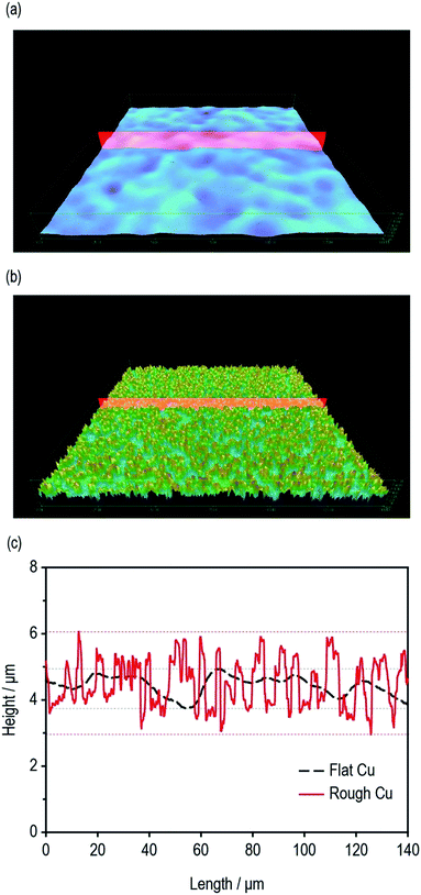 | ||
| Fig. 1 Surface 3D morphologies of (a) flat Cu and (b) rough Cu. (c) Depth profiles of flat Cu and rough Cu. | ||
The morphological properties of two different Cu foils, i.e., a flat Cu and a rough Cu, were also compared with SEM. As shown in Fig. 2a and b, the surface morphologies is clearly different but has roughly the same roughness tendencies as those seen by confocal microscopic data. On the other hands, as shown in Fig. 2c and d, the cross-sectional images of two Si electrodes coated on the flat and rough Cu foils clarify where the coated electrode materials are located and how their interfaces look. Obviously, the Si/rCu has more contact points than the Si/fCu (Fig. 3).
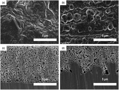 | ||
| Fig. 2 Surface SEM images of (a) flat Cu and (b) rough Cu. Cross-sectional images of (c) Si/fCu/622 and (d) Si/rCu/622. | ||
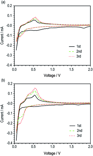 | ||
| Fig. 3 Cyclic voltammograms of unit cells with (a) Si/fCu/622 and (b) Si/rCu/622 (scan rate = 0.1 mV s−1). | ||
The electrochemical activities of the two Si electrodes (Si/fCu/622 and Si/rCu/622) were evaluated using a CV test. The Si/rCu/622 electrodes exhibited a slightly higher current density during the first cycling, which continuously became much larger in the subsequent cycling. Finally, Si/rCu/622 showed an oxidative current of 0.16 mA in the third cycle, which was twice as high as that of the reference Si/fCu/622 (0.085 mA). This capacity increasing behavior of Si/rCu means that more Si particles on the rough Cu foils were easily activated to participate in electrochemical reactions under the same voltage change because of more contact points at the interface between electrode coating layer and current collectors.
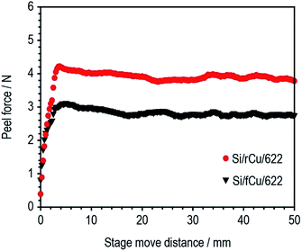
The adhesion strength of two different types of Si electrodes (Si/fCu/622 and Si/rCu/622) was measured and compared. As shown in Fig. 4, Si/rCu/622 showed higher adhesion strength to that of Si/fCu/622, which is equivalent to an increase of approximately 151% (Si/fCu/622 = 89.7 N m−1, Si/rCu/622 = 135.7 N m−1).
This enhancement is related to the better interfacial adhesion properties of Si electrodes on the rough Cu foil. After the peel test, the surface structure of Si electrodes was monitored using a digital camera. As shown in Fig. 5a and b, a large amount of Cu current collector was exposed after the peel test for Si/fCu/622, whereas Si composite still covered the entire region of the Cu current collector for Si/rCu/622. To facilitate understanding of the phenomenon, the peeling mechanism of each Si electrode was illustrated in the schematic figures. As shown in Fig. 5c, the Si/fCu/622 was delaminated mainly from the interface between Si electrode composites and Cu current collectors. On the other hand, as shown in Fig. 5d, the Si/rCu/622 was able to maintain a stable interface between the Si composite and the Cu current collector due to physical interlocking, resulting in peeling near the middle of the electrodes.
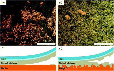 | ||
| Fig. 5 Digital images of the electrode surfaces of (c) Si/fCu/622 and (d) Si/rCu/622 after the peel test. Schematic illustration of the peel test of (a) Si/fCu/622 and (b) Si/rCu/622. | ||
We attempted to determine the interfacial adhesion strength of Si/rCu/622 using a SAICAS. This technique can measure the adhesion strength at a specific depth by cutting the electrode with a micro blade.19,20 We found that the interfacial adhesion strength of the Si/rCu/622 was still higher than that of the Si/fCu/622 (Si/rCu/622 = 292.2 N m−1, Si/fCu/622 = 231.0 N m−1; Fig. S1, ESI†), but the increase of 121% was not comparable to that measured by the peel test. This inconsistency might be related to the measurement limitation of SAICAS. What we measured was not the real interfacial strength but rather an averaged value of the interfacial and bulk adhesion strengths (Fig. S2, ESI†).
We investigated the effect of the surface roughness of Cu current collector on electrochemical performance of Si electrodes. The electrochemical properties of the Si/fCu and Si/rCu were evaluated with 2032 coin-type half-cells. Two different electrode compositions were tested to investigate the binder content effects (Si/rCu/622 and Si/rCu/811 for rough Cu foil and Si/fCu/622 and Si/fCu/811 for flat Cu foil).
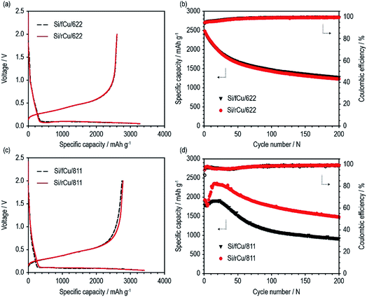
As shown in Fig. 6 and Table 1, both Si electrodes delivered quite high specific discharge capacities of 2600 to 2800 mA h g−1 and initial coulombic efficiencies (ICEs) of 79 to 82%, which indicates that neither the roughness nor the binder content has an effect at the early stage of cycling. On the other hand, their cycle performances were surprisingly different from each other, depending on the Cu foil type and binder content. There was no difference in the discharge capacity retention behavior or coulombic efficiency values of the Si electrodes containing 60 wt% of Si active materials regardless of Cu foil type (Si/fCu/622 and Si/rCu/622). Both types of Si electrodes delivered similar discharge capacities of approximately 1300 mA h g−1 and exhibited an average CE of 98.6% for 200 cycles. In contrast, the Si electrodes having a lower binder content of 10 wt% were sensitive to the Cu foil roughness. Si/rCu/811 showed much better cycle performance, maintaining its discharge capacity of approximately 1500 mA h g−1 after 200 cycles, whereas the Si/fCu/811 delivered 900 mA h g−1 under the same operating conditions.
| Charge capacity (mA h g−1) | Discharge capacity (mA h g−1) | Coulombic efficiency (%) | Discharge capacity after 200th cycle (mA h g−1) | |
|---|---|---|---|---|
| Si/fCu/622 | 3267 | 2607 | 79.8 | 1276 |
| Si/rCu/622 | 3279 | 2602 | 79.4 | 1229 |
| Si/fCu/811 | 3355 | 2750 | 81.9 | 914 |
| Si/rCu/811 | 3404 | 2782 | 81.7 | 1479 |
After cycling, the interface between Si electrode and Cu current collector was observed. The Si electrodes containing 60 wt% of Si active materials regardless of Cu foil type (Si/fCu/622 and Si/rCu/622) showed a firm adhesion between Si electrode and Cu current collector after cycling (Fig. S3, ESI†). Si/fCu/811 showed much cracking and peeling between Si electrode and Cu foil compared to Si/rCu/811 (Fig. S4, ESI†). From these results, we discerned that the better interfacial adhesion properties of Si electrodes and rough Cu foils resulted in improved cycle performance. In this regard, the total cell resistance of fCu-based Si electrodes was larger compared to those of rCu-based Si electrodes regardless of electrode composition (Fig. S5, ESI†).
The roughness effects of the Cu foils were also investigated with flexible pouch-type LIBs having the same Si electrodes, Si/fCu/622 and Si/rCu/622, that were used in experiment described above. Both Si electrodes were electrochemically cycled in the rolled conformation with a radius of 6.5 mm (Fig. S6, ESI†). As shown in Fig. 7, contrary to the cycle performance under the mechanically unstressed condition (Fig. 6), the Si/rCu/622 showed much better cycle performance than the Si/fCu/622. In other words, the roughness effects of Cu foil are more evident in the flexible batteries.
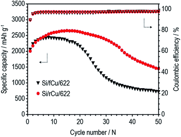 | ||
| Fig. 7 Cycle performances of pouch-type flexible batteries (bending radius = 6.5 mm) at a current density of 1.2 A g−1 for 50 cycles. | ||
The capacity increase of Si electrode at the early stage of cycling was observed as shown in Fig. 6d and 7. This behavior is attributed to the Si electrode stabilization.2,5,21 Electrically isolated Si particles can be rearranged and electrically reconnected during repeated volume expansion and contraction, resulting in capacity increase. Although the exact mechanism for this behavior is currently unclear, our results suggest that the Si electrode stabilization depends not only on the composition of Si electrode but also on the battery type.
4. Conclusions
The roughness effects of Cu foils on Si electrodes in LIBs were successfully investigated by analyzing the interfacial adhesion property and performing electrochemical performance tests. In particular, not only peel test but also SAICAS was applied to compare the adhesion properties of Si electrodes in more detail. When Cu foils with a roughness of 3 μm were used for the Si electrode, they deliver much better cycle performance, especially under lower binder content and in the mechanically stressed condition. Thus, increasing the roughness of the Cu foil, or any other current collector, should be carefully considered for electrode materials having a large volume change such as Si.Acknowledgements
This work was supported by the Basic Science Research Program through the National Research Foundation of Korea (NRF) funded by the Ministry of Education (NRF-2016R1D1A3B03933293). This work was also supported by the Human Resource Training Program for Regional Innovation and Creativity through the Ministry of Education and National Research Foundation of Korea (NRF-2014H1C1A1066977). We acknowledge the ILJIN Materials Co. Ltd., which provided flat and rough Cu foils.References
- M. H. Ryou, J. Kim, I. Lee, S. Kim, Y. K. Jeong, S. Hong, J. H. Ryu, T. S. Kim, J. K. Park and H. Lee, Adv. Mater., 2013, 25, 1571–1576 CrossRef CAS PubMed
.
- Y. K. Jeong, T.-w. Kwon, I. Lee, T.-S. Kim, A. Coskun and J. W. Choi, Nano Lett., 2014, 14, 864–870 CrossRef CAS PubMed
.
- J. Choi, K. Kim, J. Jeong, K. Y. Cho, M.-H. Ryou and Y. M. Lee, ACS Appl. Mater. Interfaces, 2015, 7, 14851–14858 CAS
.
- C. Liu, F. Li, L. P. Ma and H. M. Cheng, Adv. Energy Mater., 2010, 22, E28–E62 CrossRef CAS PubMed
.
- J. R. Szczech and S. Jin, Energy Environ. Sci., 2011, 4, 56–72 CAS
.
- B. Liang, Y. Liu and Y. Xu, J. Power Sources, 2014, 267, 469–490 CrossRef CAS
.
- B. Lestriez, S. Bahri, I. Sandu, L. Roué and D. Guyomard, Electrochem. Commun., 2007, 9, 2801–2806 CrossRef CAS
.
- J.-S. Bridel, T. Azais, M. Morcrette, J.-M. Tarascon and D. Larcher, Chem. Mater., 2009, 22, 1229–1241 CrossRef
.
- A. Magasinski, B. Zdyrko, I. Kovalenko, B. Hertzberg, R. Burtovyy, C. F. Huebner, T. F. Fuller, I. Luzinov and G. Yushin, ACS Appl. Mater. Interfaces, 2010, 2, 3004–3010 CAS
.
- I. Kovalenko, B. Zdyrko, A. Magasinski, B. Hertzberg, Z. Milicev, R. Burtovyy, I. Luzinov and G. Yushin, Science, 2011, 334, 75–79 CrossRef CAS PubMed
.
- B. Koo, H. Kim, Y. Cho, K. T. Lee, N. S. Choi and J. Cho, Angew. Chem., Int. Ed., 2012, 51, 8762–8767 CrossRef CAS PubMed
.
- C. Erk, T. Brezesinski, H. Sommer, R. Schneider and J. r. Janek, ACS Appl. Mater. Interfaces, 2013, 5, 7299–7307 CAS
.
- X.-M. Liu, Z. dong Huang, S. woon Oh, B. Zhang, P.-C. Ma, M. M. Yuen and J.-K. Kim, Compos. Sci. Technol., 2012, 72, 121–144 CrossRef CAS
.
- X. Su, Q. Wu, J. Li, X. Xiao, A. Lott, W. Lu, B. W. Sheldon and J. Wu, Adv. Energy Mater., 2014, 4, 1300882 CrossRef
.
- K.-L. Lee, J.-Y. Jung, S.-W. Lee, H.-S. Moon and J.-W. Park, J. Power Sources, 2004, 129, 270–274 CrossRef CAS
.
- Y.-L. Kim, Y.-K. Sun and S.-M. Lee, Electrochim. Acta, 2008, 53, 4500–4504 CrossRef CAS
.
- T. Hang, H. Nara, T. Yokoshima, T. Momma and T. Osaka, J. Power Sources, 2013, 222, 503–509 CrossRef CAS
.
- D. Reyter, S. Rousselot, D. Mazouzi, M. Gauthier, P. Moreau, B. Lestriez, D. Guyomard and L. Roué, J. Power Sources, 2013, 239, 308–314 CrossRef CAS
.
- B. Son, M.-H. Ryou, J. Choi, T. Lee, H. K. Yu, J. H. Kim and Y. M. Lee, ACS Appl. Mater. Interfaces, 2013, 6, 526–531 Search PubMed
.
- K. Kim, S. Byun, I. Cho, M.-H. Ryou and Y. M. Lee, ACS Appl. Mater. Interfaces, 2016, 8, 23688–23695 CAS
.
- H. Wu, G. Chan, J. W. Choi, I. Ryu, Y. Yao, M. T. McDowell, S. W. Lee, A. Jackson, Y. Yang and L. Hu, Nat. Nanotechnol., 2012, 7, 310–315 CrossRef CAS PubMed
.
Footnotes |
| † Electronic supplementary information (ESI) available. See DOI: 10.1039/c7ra04598k |
| ‡ These authors contributed equally to this work. |
| This journal is © The Royal Society of Chemistry 2017 |

