DOI:
10.1039/C6QM00300A
(Research Article)
Mater. Chem. Front., 2017,
1, 1156-1164
Understanding the interfacial interactions between dopamine and different graphenes for biomedical materials†
Received
22nd November 2016
, Accepted 20th December 2016
First published on 22nd December 2016
Abstract
The interaction mechanisms of dopamine (DA) on pristine graphene (G), Stone–Wales defective graphene (DG), graphene oxide (GO), and Fe-doped graphene (Fe-G) surfaces have been investigated via simulation. It has been found that the adsorption configurations of DA molecules on graphene-based materials greatly affect the interaction energies between the DA molecules and graphene surfaces. The interactions between a DA molecule and G or DG surface were predominantly regarded as a physical adsorption process, wherein a DA molecule was chemisorbed on the GO surface with –OH in the DA molecule pointing towards the GO surface. It was also demonstrated that DA could be chemisorbed on the Fe-G surface. The study forms a guideline for designing graphene-based materials with specific structure or chemical groups to satisfy the demands for DA related applications.
1. Introduction
Graphene, an sp2 nanomaterial, has attracted significant research interest following the first report in 2004 on its inherent excellent properties.1 It has shown a broad range of potential applications in many areas.2–6 For example, it is used in nanocomposites as a functional nanofiller,7 in lithium-ion battery as a cathode material,8 in tissue engineering as a biocompatible material, and in sensors as an electrochemical sensing material.9 However, interface behavior is still a key issue for graphene-based materials. Therefore, the surface physical and chemical properties of graphene would be very important issues for graphene-based materials, which are directly related to the applications of graphene.
Inspired by mussels' firm adhesion on solid surfaces, polydopamine, with a molecular structure similar to that of 3,4-dihydroxy-L-phenylalanine (DOPA), has attracted extensive attention as a novel coating material.10 Besides excellent adhesion properties, dopamine (DA) also exhibits outstanding biocompatibility. Thus, DA is induced into many materials to be a part of the composites to improve adhesion, biocompatibility, and other properties. Liu et al.11 utilized Pd-loaded amino acid-modified Fe3O4 nanoparticles for sensing DA. This study demonstrated that nanoparticles could be applied to analyze DA in human serum samples with excellent results. Kang et al.12 studied the immobilization of epidermal growth factor on titanium and stainless steel surfaces via DA treatment. This showed that DA-grafted metal surfaces had excellent adhesion ability for the epidermal growth factor. Cao et al.13 demonstrated that DA-modified halloysite nanotubes possessed excellent loading capacity for laccase compared to natural halloysite nanotubes. Phua et al.14 prepared DA-modified clay to reinforce the polyether polyurethane and the interfacial interactions were greatly improved. The adhesion behavior of DA on the graphene-based materials was also very attractive for the potential applications of graphene-based materials for DA detections. Ren et al.15 studied the competitive adsorption behavior of DA and rhodamine 6G on graphene oxide (GO) surfaces. They found that the adsorption behavior of both DA and rhodamine 6G could be described by the traditional Langmuir isotherms. The interactions between DA and GO were greater than those between rhodamine 6G and GO. Ramakrishnan et al.16 synthesized Pt-decorated graphene–carbon nanotubes for DA sensing. Their study indicated that the material could be a promising choice for biosensors. DA is an important neurotransmitter and its fantastic role as a neurotransmitter in the brain was demonstrated to be directly related to the accumulation of Fe in vivo.17 Although graphene-based materials were demonstrated to be used for detecting DA, a detailed understanding of DA interaction with graphene-based materials at the molecular level remains unavailable.
Understanding the mechanism of interactions between graphene and DA is crucial for designing graphene-based biomedical materials and devices. However, the interaction between DA and graphene is still not fully understood, which hinders the future development of graphene/DA-based materials for different applications. Molecular modeling is an effective way to study the interactions between DA- and graphene-based material surfaces and provide information at the atomic and electronic level. Density functional theory (DFT) has been employed to investigate the interactions between various molecules (amino acids, gas molecules, metal clusters, and so on) and graphene or carbon nanotube (CNT) surfaces. Fouineau et al.18 studied the interactions between DA and iron oxide by experimental and ab initio calculations and the π-donor character of DA was demonstrated by the DFT calculations. Our previous studies indicated that the surface defects, doping atoms, and functional groups would greatly affect the interactions between graphene surfaces and molecules.19–21 This study aims to investigate the adsorption mechanism of DA on graphene-based nanostructures.
2. Theoretical methods
2.1 Model building
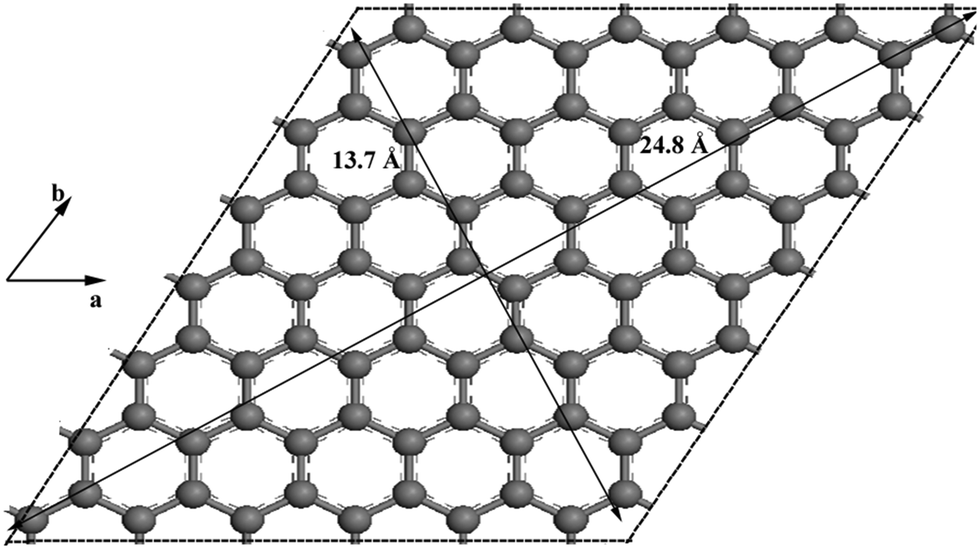
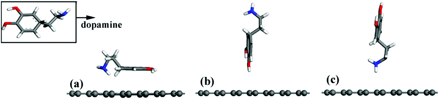
DA on pristine graphene (G).
The G surface, as shown in Fig. 1, that consists of 84 carbon atoms was constructed with 7 carbon atom rings along the a direction and 7 carbon atom rings along the b direction. The surface area is about (24.8 × 13.7)/2 = 169.8 Å2.
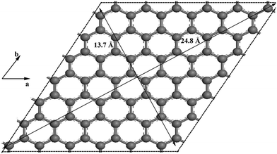 |
| | Fig. 1 The ball and stick model of a graphene sheet. | |
A periodic boundary condition was employed to model the surface, and a vacuum slab with a thickness of 30 Å was added to avoid the influence of neighboring cells. Three configurations of a DA molecule were investigated on the G surface with the consideration of different chemical groups of a DA molecule as the interaction sites during the adsorption process. Three typical configurations are described: (a) the G–DA lying model (Fig. 2(a)): the carbon atom ring of a DA molecule was parallel to the graphene surface; (b) the G–DA standing-OH model (Fig. 2(b)): a DA molecule was perpendicular to the graphene surface with the hydroxyl groups (–OH) approaching the graphene surface; and (c) the G–DA standing-NH2 model (Fig. 2(c)): a DA molecule was perpendicular to the graphene surface with the amino group (–NH2) approaching the graphene surface. Note that there are also many other possible initial configurations of a DA molecule on a graphene surface. However, the present models only represent the typical interaction modes between DA and graphene with reference to the roles of the chemical groups of a DA molecule during the adsorption process.
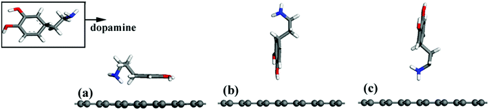 |
| | Fig. 2 Different initial configurations of a dopamine molecule on a pristine graphene sheet (a) lying, (b) standing with –OH, and (c) standing with –NH2. | |
DA on defective graphene (DG).
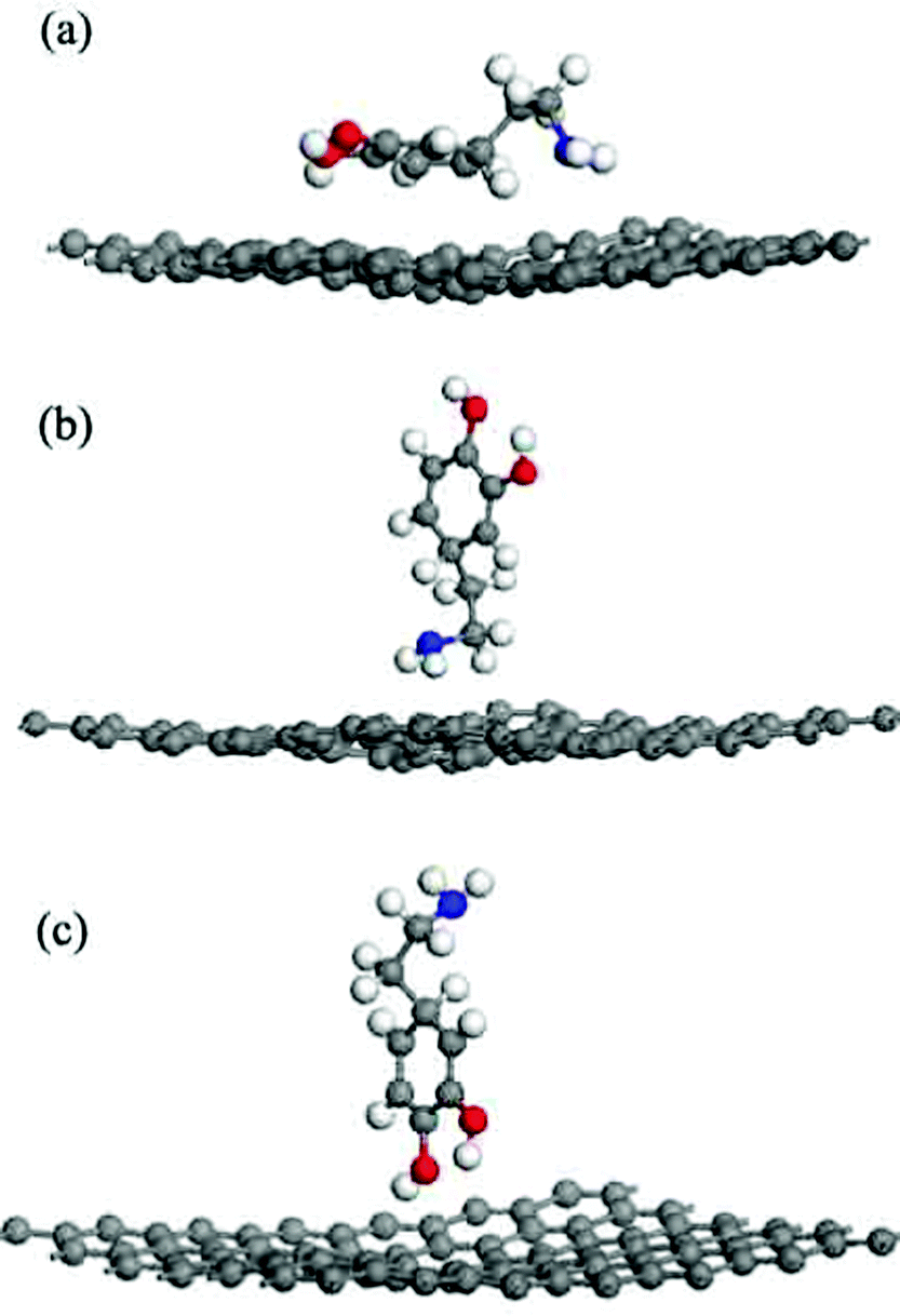
The Stone–Wales defected graphene surface model was built according to the method reported in literature.20 Three typical models were built to investigate the effect of the defects on the interactions between a DA molecule and DG surface: (a) the DG–DA lying model (Fig. 3(a)): the carbon atom ring of a DA molecule was parallel to the surface; (b) the DG–DA standing-NH2 model (Fig. 3(b)): a DA molecule was perpendicular to the DG surface with the amino group (–NH2) approaching the surface, and (c) the DG–DA standing-OH model (Fig. 3(c)): a DA molecule was perpendicular to the DG surface with the hydroxyl groups (–OH) approaching the surface.
 |
| | Fig. 3 Different initial configurations of a dopamine molecule on the graphene sheet with the Stone–Wales defect (a) lying, (b) standing with –NH2, and (c) standing with –OH. | |
DA on GO.
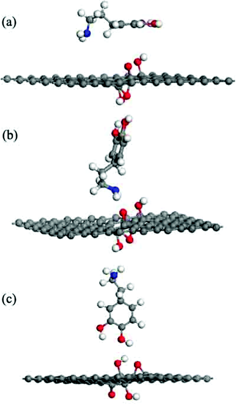
The GO model had a C8O2(OH)2 unit that interacted with different chemical groups in a DA molecule. The C8O2(OH)2 unit was located at the center of the carbon sheet, containing two para-epoxy groups (para-O) at the opposite side of the C-plane and two para-hydroxyl (para-OH) groups at the upside of the C-plane. Three typical models were built to investigate the interactions between DA and GO: (a) the GO–DA lying model (Fig. 4(a)): the carbon atom ring of a DA molecule was parallel to the surface; (b) the GO–DA standing-NH2 model (Fig. 4(b)): a DA molecule was perpendicular to the GO surface with the amino group (–NH2) approaching the surface; and (c) the GO–DA standing-OH model (Fig. 4(c)): a DA molecule was perpendicular to the GO surface with the hydroxyl groups (–OH) approaching the surface.
 |
| | Fig. 4 Different initial configurations of a dopamine molecule on the graphene oxide sheet (a) lying, (b) standing with –NH2, and (c) standing with –OH. | |
DA on an Fe-doped graphene (Fe-G).
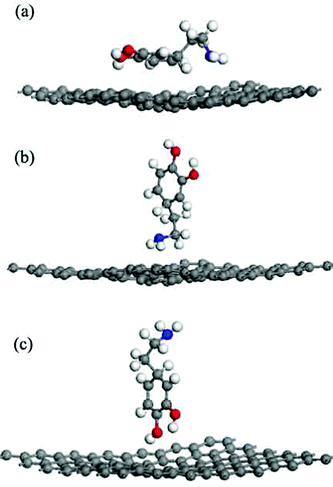
The Fe-G model had been built by replacing a C atom on the graphene sheet with an Fe atom. The details of the Fe-G model have been discussed in our former report19 and three typical models are discussed as follows: (a) the Fe-G–DA lying model (Fig. 5(a)): the carbon atom ring of a DA molecule was parallel to the Fe-G surface; (b) the Fe-G–DA standing-NH2 model (Fig. 5(b)): a DA molecule was perpendicular to the Fe-G surface with the amino group (–NH2) approaching the surface; and (c) the Fe-G–DA standing-OH model (Fig. 5(c)): a DA molecule was perpendicular to the Fe-G surface with the hydroxyl groups (–OH) approaching the surface.
 |
| | Fig. 5 Different initial configurations of a dopamine molecule on an Fe-doped graphene sheet (a) lying, (b) standing with –NH2, and (c) standing with –OH. | |
2.2 Simulation parameters
All the simulations were performed by the DFT program Dmol3 in Materials Studio (Accelrys, San Diego, CA) wherein the physical wave functions were expanded in terms of numerical basis sets.22 A DNP double numerical basis set,23 which is comparable to the 6-31G** basis set, was utilized during the simulation.23,24 The core electrons were treated with DFT semicore pseudopotentials. The exchange–correlation energy was calculated using the Perdew–Burke–Ernzerhof generalized gradient approximation.25 Special point sampling integration over the Brillouin zone was employed using the Monkhorst–Pack schemes with a 5 × 5 × 1 k-point mesh.26 A Fermi smearing of 0.005 Ha (1 Ha = 27.211 eV) and a global orbital cut-off of 5.2 Å were employed. The convergence criteria for the geometric optimization and energy calculation were set as follows: (1) a self-consistent field tolerance of 1.0 × 10⁻⁶ Ha per atom; (2) an energy tolerance of 1.0 × 10⁻⁵ Ha per atom; (3) a maximum force tolerance of 0.002 Ha Å−1; and (4) a maximum displacement tolerance of 0.005 Å. Dmol3 produces highly accurate results while keeping the computational cost fairly low. The optimized G surface shows a C–C bond length of 1.42 Å. This finding was in good agreement with previous reports.19,20 The bond lengths and bond angles of a DA molecule from Dmol3 and from other simulation studies were thoroughly compared. The reproducibility of previously reported data validates the applicability of Dmol3 to the present systems.20
2.3 Adsorption energy
The adsorption energy (Eads), indicating the intensity of interaction between DA and graphene surfaces, was derived according to the following equation:| | | Eads = Edopamine+graphene − (Edopamine + Egraphene) | (1) |
where Edopamine+graphene, Edopamine, and Egraphene represent the total energy of the adsorption system, the energy of DA, and the energy of graphene, respectively. A negative Eads corresponds to a stable adsorption and a more negative Eads results in a more stable adsorption system. Table 1 shows the Eads values of various systems. The electron density difference reveals the change of electron density during adsorption, which is calculated by subtracting the electron density of the isolated DA (ρDA) and graphene surface (ρgraphene) from the total electron density of the system (ρDA+graphene), as shown in the following equation:| | | Δρ = ρDA+graphene − ρDA − ρgraphene | (2) |
Table 1 Adsorption energies of a dopamine (DA) molecule on a pristine graphene (G), a defective graphene (DG), a graphene oxide (GO), and an Fe-doped graphene (Fe-G) surface (unit: eV; Etotal: energy of both graphene substrate and DA molecule; Esurface: energy of the graphene substrate; EDA: energy of the DA molecule)
| Models |
E
total
|
E
surface
|
E
DA
|
E
ads
|
| Pristine graphene–dopamine |
| G–DA-lying |
−778.115 |
−670.092 |
−106.512 |
−1.51 |
| G–DA-standing-OH |
−777.536 |
−670.103 |
−106.541 |
−0.89 |
| G–DA-standing-NH2 |
−777.387 |
−670.105 |
−106.497 |
−0.79 |
| Defective graphene–dopamine |
| DG–DA-lying |
−773.722 |
−665.237 |
−106.506 |
−1.97 |
| DG–DA-standing-OH |
−772.555 |
−665.234 |
−106.516 |
−0.81 |
| DG–DA-standing-NH2 |
−772.584 |
−665.235 |
−106.470 |
−0.87 |
| Graphene oxide−dopamine |
| GO−DA-lying |
−795.966 |
−688.687 |
−106.408 |
−0.87 |
| GO−DA-standing-OH |
−798.421 |
−688.667 |
−104.810 |
−4.94 |
| GO−DA-standing-NH2 |
−796.498 |
−688.534 |
−106.491 |
−1.47 |
| Fe-Doped graphene−dopamine |
| Fe-G-lying |
−770.763 |
−661.523 |
−106.301 |
−2.94 |
| Fe-G-standing-OH |
−769.130 |
−661.399 |
−106.429 |
−1.30 |
| Fe-G-standing-NH2 |
−770.088 |
−661.404 |
−106.548 |
−2.14 |
3. Results and discussion
3.1 DA on G
The adsorption energies (Eads) of all three configurations are negative, as shown in Table 1.
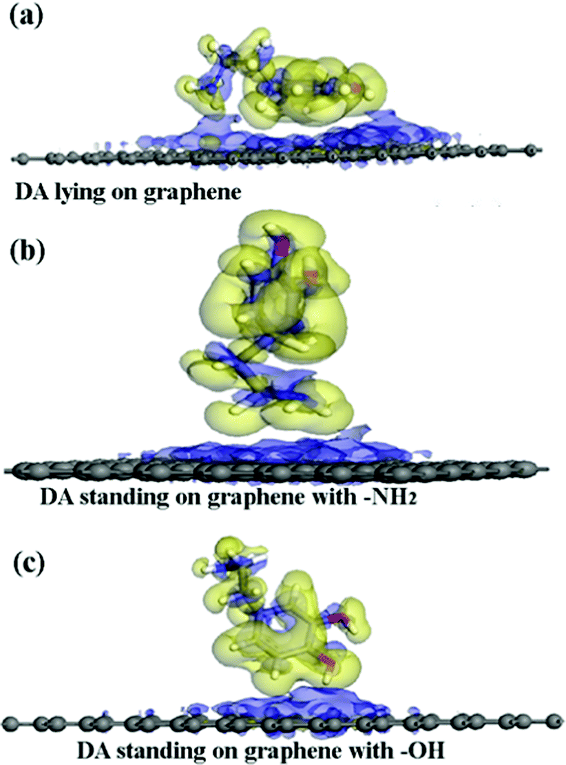
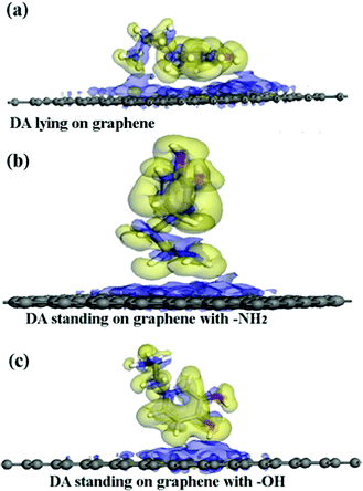
This result indicates that the DA molecule could thermodynamically adsorb on a G surface in all three cases. Among the three configurations shown in Fig. 2, when a DA molecule laid on the G surface, the Eads (about −1.5 eV) was the largest. When a DA molecule stood on the G surface with a –OH group or an –NH2 group, the Eads values were very similar (about –0.8 to –0.9 eV). This demonstrated that the configuration of the adsorbent affects the interaction between the adsorbent and material surfaces. The adsorption energy results show that different DA configurations on the G surfaces lead to different adsorption energies. The distance between a lying DA molecule and the G sheet was about 0.34 nm, which was very close to that of the layer distance in graphite.27 According to a report28, it can be concluded that the interactions between the lying DA molecule and G surface are mainly π–π interactions, which are characteristic of a noncovalent bond. Fig. 6 shows the electron density difference of the isosurfaces of the G–DA models. The electron density difference reveals the change of electron density during adsorption. The charge accumulation and charge depletion are represented by blue and yellow colors, respectively. From Fig. 6(a), a slight overlapping of electrons could be observed between the DA molecule and G surface through –NH2 and –OH groups of a DA molecule in the G–DA lying model. However, for the other two models (the G–DA standing-NH2 model and the G-DA standing-OH model, see Fig. 6(b) and (c)), charge accumulation and depletion could be found which indicated that the electron transfer was mainly from the DA molecule to the G surface. No apparent overlapping of electrons could be observed. The results were consistent with those of the Eads values. The interactions between a DA molecule and a G surface were related with the adsorption configurations of the DA molecule; in other words, the number of the DA molecule adsorption sites implied the presence of the interactions. The interactions between the –NH2 of DA and G were comparable with those between the –OH of DA and G.
 |
| | Fig. 6 The electron density differences of the DA–G sheet models. The charge accumulation and charge depletion are represented by blue and yellow colors, respectively. (a) The DA molecule lying on the G surface model, (b) the DA molecule standing on the G surface with –NH2, and (c) the DA molecule standing on the G surface with –OH (isosurface value: 0.002 electrons per Å3). | |
3.2 DA on DG
The various imperfections in graphene are mainly composed of point defects and substitution atoms. These defects are commonly chemically active sites and can greatly influence the chemical properties of graphene. The Stone–Wales defect is one of the most common types of point defects in graphene, which is apparently different from the vacancy defect. The formation of the Stone–Wales defect is due to one of the unique properties of graphene, that is, it can reconstruct to form non-hexagonal carbon rings.29 The adsorption of a DA molecule on a graphene surface with the Stone–Wales defect was considered in this study (Fig. 3).
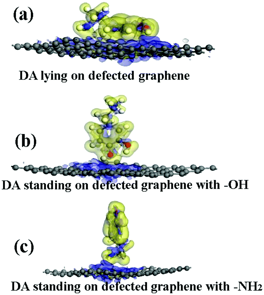
The adsorption energies (Eads) of three configurations are negative, as shown in Table 1, indicating that a DA molecule could be stably adsorbed on a DG surface. The values of Eads for the DA–DG models are comparable with those of the DA–G models when a DA molecule stands on a DG surface with –NH2 or –OH groups (see Table 1). When a DA molecule lays on the DG surface, the Eads is about −1.97 eV, which is larger than that of a DA molecule lying on a G surface (about −1.51 eV). This might be due to the reconstruction of graphene caused by the Stone–Wales defect, which induces wrinkling in the graphene surface. The wrinkling of graphene decreases the interaction distance between the DA molecule and graphene surface. The electron density difference was also analyzed for the DA–DG systems. Fig. 7 indicates that during the interaction process of DA molecule on the DG surface, the electrons trended to transfer from the DA molecule to the DG surface, which was similar to the effect observed with the DA–G systems.
 |
| | Fig. 7 The electron density difference of the DA–DG models. The charge accumulation and charge depletion are represented by blue and yellow colors, respectively. (a) The DA molecule lying on the DG surface, (b) the DA molecule standing on the DG surface with –OH, and (c) the DA molecule standing on the DG surface with –NH2 (isosurface value: 0.002 electrons per Å3). | |
3.3 DA on GO
According to the previous reports,30,31 the GO model was constructed by adding two para-OH groups at one side of the carbon plane and two para-epoxy groups at the opposite side of the carbon plane (see ESI,† Fig. S1). After the geometric optimization, one –OH points to the ortho epoxy oxygen and the other –OH points to the hexagonal center of the adjacent carbon ring. The C–O bond lengths of the two para-epoxy groups in the abovementioned model are 1.45 Å, 1.43 Å, 1.45 Å, and 1.48 Å. The C–O bond lengths of –OH on the GO model are 1.45 Å and 1.48 Å. The O–H bond lengths are about 0.97 Å. These bond lengths are comparable with the previously reported values.30,31
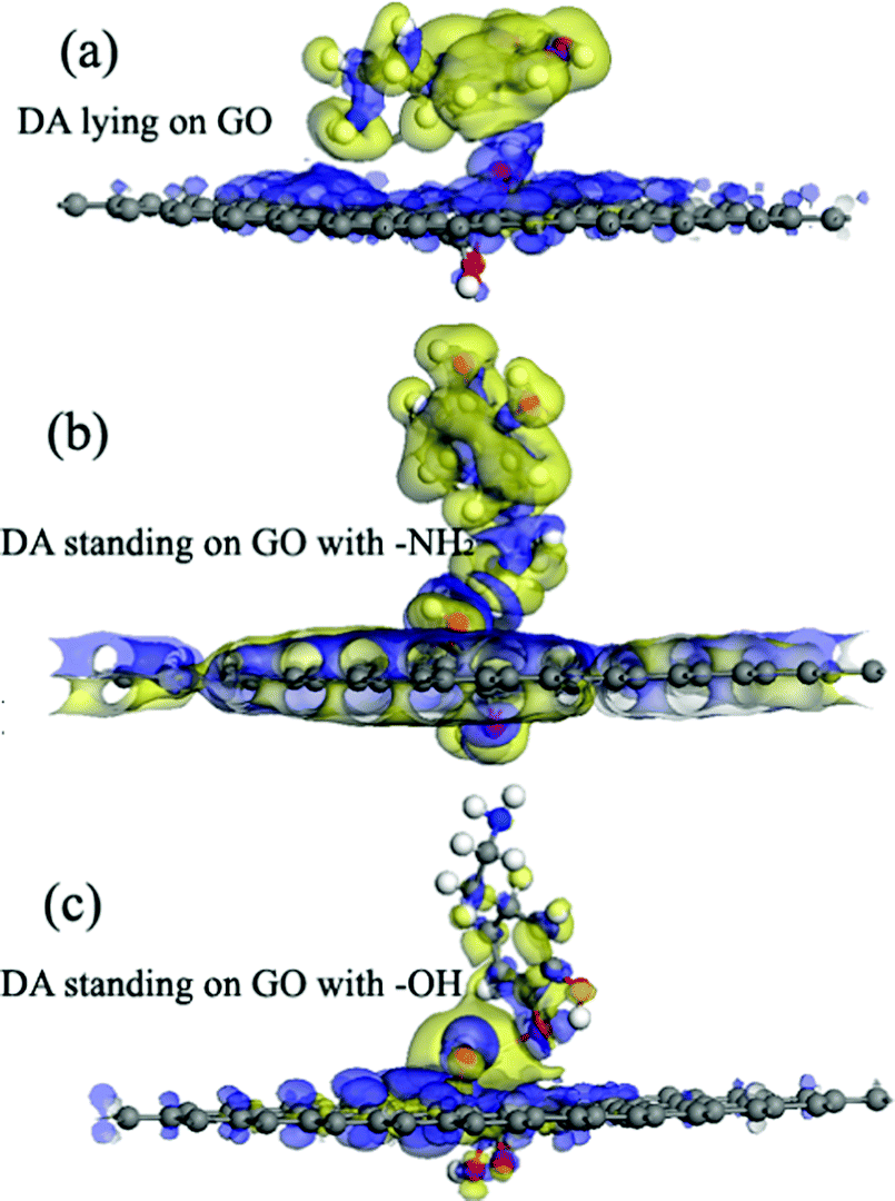
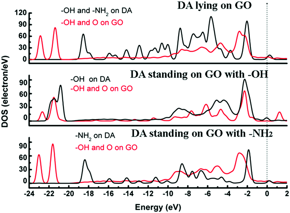
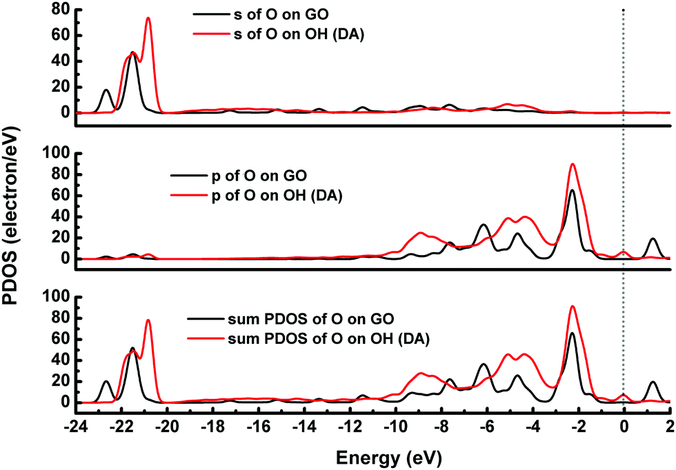
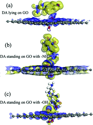
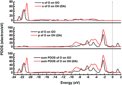
The adsorption energies (Eads) of three configurations are negative, which indicate that a DA molecule could be stably adsorbed on the GO surface. For the models where the DA molecule is standing on the GO surface (with –NH2 or –OH), the Eads values were –1.47 eV and –4.94 eV, respectively. These Eads values are larger than those of the DA molecule lying on the GO surface (about –0.8 eV) (see Table 1). For the DA molecule standing on the GO surface with the –OH group, the distance between the H atom of one of the OH groups in a DA molecule and the ortho epoxy oxygen is about 0.99 Å, whereas the bond length of the –OH changes to about 1.8 Å. This is the reason why a DA molecule could firmly adsorb on a GO surface, with –OH pointing to the surface. For the models where DA is standing on GO with –NH2 and where DA is lying on GO, the distance between DA and GO is apparently larger than that of the DA standing on GO with –OH (see ESI,† Fig. S2). Comparing DA standing on GO with –NH2 and DA lying on GO models, the distance between DA and GO in the first case is smaller than that of the second case. However, the distance in the first case is still larger than the general hydrogen bond length, which is about 1.9 Å. It means that in the DA standing on GO with –NH2 and the DA lying on GO models, the interactions between DA and GO could also be due to physisorption. Therefore, combining the results of the bond length analysis and the Eads results, a DA molecule could be chemisorbed on the GO surface with a specific orientation. Fig. 8 shows the electron density difference results, from which the apparent difference could be found between the model where DA molecule is standing on a GO surface with –OH, and the other two models. Obvious charge transfer from a DA molecule to the GO surface could be found for the previous model. To investigate the strong interactions between a DA molecule and a GO surface with the specific orientation, the PDOS was carefully studied. Fig. 9 shows the PDOS of the active chemical groups in the three DA–GO systems. It can be seen that there are peak overlaps in the range of –18 to –22 eV and –4 to –1 eV for the model where DA molecule is standing on the GO surface with –OH. Fig. 10 further shows the chemical interactions between the –OH group of a DA molecule and the ortho epoxy oxygen of a GO surface, and the s and p orbital overlapping in the specific energy ranges could be clearly observed. It is reported that a DA molecule successfully grafted on the GO or G surface has been demonstrated by XPS results, where the C–N peaks in DA appeared after the chemical process.32 Although it was demonstrated that DA could reduce GO to G and firmly cap on the G surface, the detailed interaction mechanisms have not yet been understood.33–38 Our calculation indicated that DA prefers to interact with GO through the phenolic hydroxyl group rather than the amino group.
 |
| | Fig. 8 The electron density difference of the DA–GO models. The charge accumulation and charge depletion are represented by blue and yellow colors, respectively. (a) The DA molecule lying on the GO surface, (b) the DA molecule standing on the GO surface with –NH2, and (c) the DA molecule standing on the GO surface with –OH (isosurface value: 0.002 electrons per Å3). | |
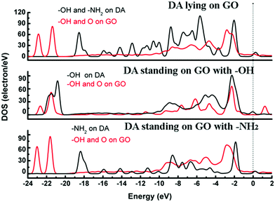 |
| | Fig. 9 DOS for the DA molecule on the GO surface. The dotted line represents the Fermi energy, which has been assigned a value of zero. | |
 |
| | Fig. 10 PDOS of the DA molecule on the GO surface. The dotted line represents the Fermi energy, which has been assigned a value of zero. | |
3.4 DA on Fe-G
Fe has been widely regarded as playing a very important role in the oxidation process of DA.17 Herein, the effect of Fe on the interactions between a DA molecule and a graphene sheet was investigated. The DFT calculations were carried out on the DA–Fe-G systems and the optimized configurations are shown in Fig. 5. The three different DA molecule initial configurations were considered in the study.
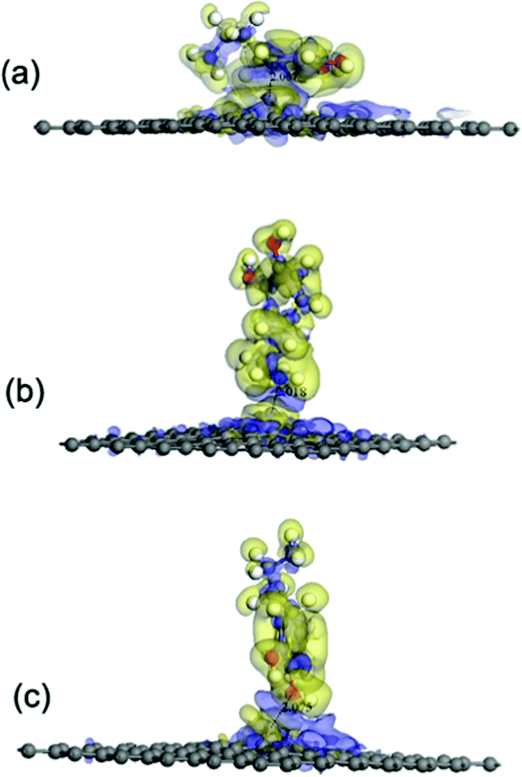
According to the results of the adsorption energy (Eads) (see Table 1), the interactions between a DA molecule and an Fe-G surface were apparently improved when compared with those of the other three graphene systems, i.e., pristine, defected, and GO, as shown in Fig. 11. It was indicated that Fe could be helpful in strengthening the interactions between DA and graphene sheets. To further study the interactions between a DA molecule and the Fe-G surface, the electron density difference was explored. It was found that an obvious electron transfer could be seen from Fe in the Fe-G sheet to the DA molecule. The amount of the transferring electrons was greatly related to the interactions between them. When a DA molecule is lying on the Fe-G surface, it owns the largest interactions between the DA molecule and the Fe-G surface, which exhibits the most apparent electron transfer (see Fig. 11). Thus, the result of the Eads corresponded with that of the electron density difference.
 |
| | Fig. 11 The electron density difference of the DA–Fe-G models. The charge accumulation and charge depletion are represented by blue and yellow colors, respectively. (a) The DA molecule lying on the Fe-G surface, (b) the DA molecule standing on the Fe-G surface with –NH2, and (c) the DA molecule standing on the Fe-G surface with –OH (isosurface value: 0.002 electrons per Å3). | |
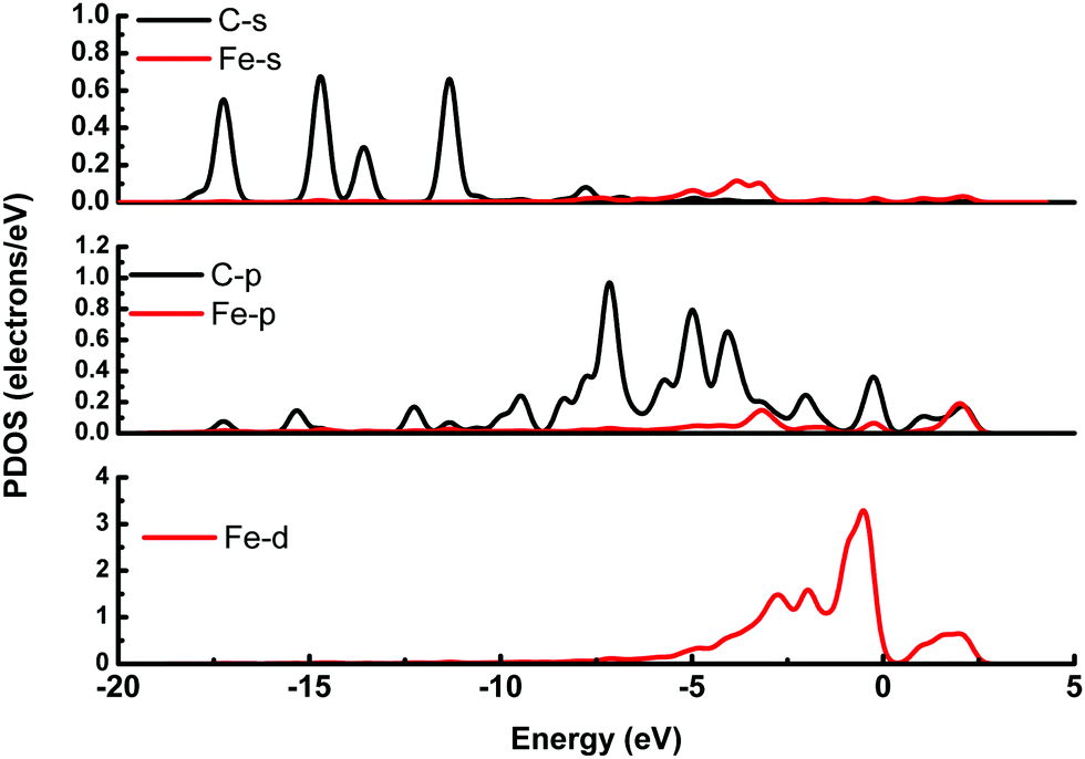
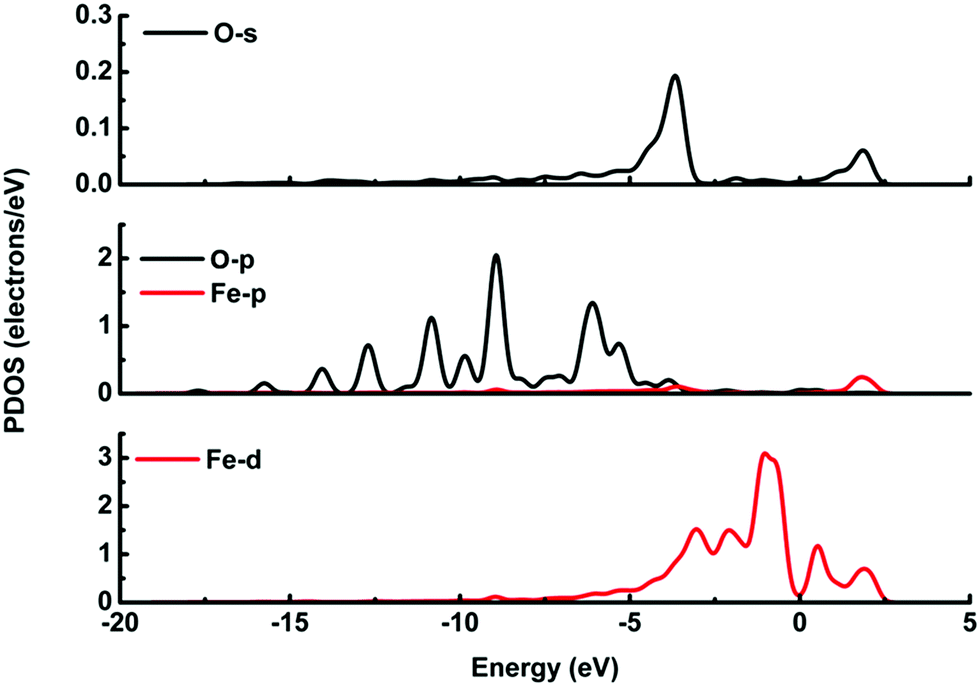
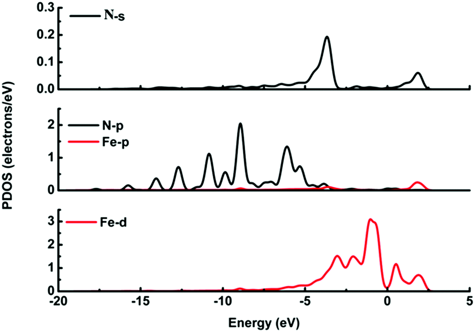
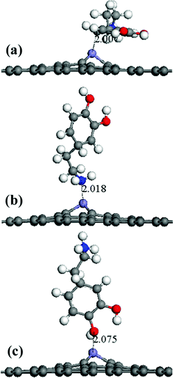
It is possible that the interactions between DA and Fe-G were chemisorption processes. For the model where the DA molecule is lying on the Fe-G surface, the Fe–C bond (about 2.0 Å) could be formed between the doped Fe and C of a DA molecule. For the DA molecule standing on the surface of Fe-G with –NH2 or –OH groups, the chemical bonds of Fe–N and Fe–O were formed. The regular Fe–O bond length is about 2.05 Å, whereas the distance between the doped Fe and O of a phenolic hydroxyl group on a DA molecule is 2.08 Å (see Fig. 11(c)). The detailed chemical interactions could be discussed through PDOS analysis, as shown in Fig. 12–14. The interactions between Fe and other atoms (C, O or N) mainly originated from the interactions of the d orbital of Fe and p orbital of other atoms. Fig. 12 exhibits the PDOS of a C atom on a DA molecule and the doped Fe atom in the DA lying on the Fe-G model. Apparent overlapping could be found between the d orbital of the doped Fe atom and the p orbital of C on the DA molecule in the range from −3 to 1 eV. Fig. 13 shows the PDOS of an O atom on −OH of DA and the doped Fe atom in the DA standing on Fe-G with –OH model. Apparent overlapping could also be found between the s orbital of an O atom on –OH and the d orbital of the doped Fe atom. Fig. 14 presents the PDOS of an N atom on –NH2 of DA and the doped Fe atom in the DA standing on Fe-G with –NH2 model. Apparent overlapping could also be found between the p orbital of an N atom on –NH2 and the d orbital of the doped Fe atom. All the electron orbital overlapping in the DA–Fe-G systems demonstrates the interactions of the electrons. Our calculations indicated that Fe could be very helpful in strengthening the interactions between DA and graphene, which correspond with the reports that Fe(III) could be very useful in the cross-linking process of polydopamine.39,40
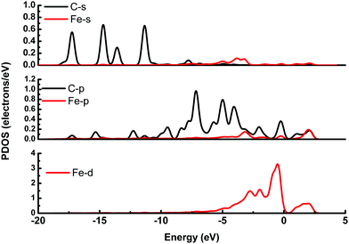 |
| | Fig. 12 PDOS of the DA molecule lying on the Fe-G surface. The s and p orbitals of a C atom on the DA molecule and the s, p, and d orbitals of a doped Fe atom on the graphene surface. | |
 |
| | Fig. 13 PDOS of the DA molecule standing on the Fe-G surface with –OH. The s and p orbitals of an O atom on –OH of the DA molecule, and s, p, and d orbitals of a doped Fe atom on the graphene surface. | |
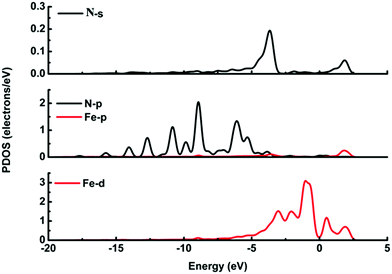 |
| | Fig. 14 PDOS of the DA molecule standing on the Fe-G surface with –NH2. The s and p orbitals of a N atom on –NH2 of the DA molecule, and s, p, and d orbitals of a doped Fe atom on the graphene surface. | |
4. Conclusions
The current study investigates the interactions between a DA molecule and various graphene-based materials. The DA molecule could be strongly physisorbed on the G surface in various orientations. The orientations of the DA molecule on the G surface could affect the active sites for interactions. The Stone–Wales defect on graphene could affect the interactions between the DA molecule and the graphene surface with specific orientations. Generally, the effect of the defects on the interactions between DA and DG was not obvious. For the DA–GO systems, the DA molecule might be chemisorbed on the GO surface with specific orientations. For the DA–Fe-G systems, the interactions between the DA molecule and the Fe-G surface can be improved by a doped Fe atom with three typical DA initial configurations. Therefore, graphene-based materials with specific structures or chemical groups could be designed to satisfy the demands for different applications of graphene-based materials. The interactions between DA and graphene could be adjusted by chemical or physical methods. This research is very meaningful for designing specific graphene-based materials for DA sensing and DA/graphene composites.
Acknowledgements
The authors thank Changsheng Liu for his advice and help during the revision of this manuscript. This research was supported by the 863 Program (No. 2015AA034202), the National Natural Science Foundation of China (NSFC; Grant No. 31300793, 31400809), the Engineering Research Center of Biomass Materials (SWUST), Ministry of Education (No. 13zxbk03), and the Special Program for Applied Research on Super Computation of the NSFC-Guangdong Joint Fund (the second phase).
References
- K. S. Novoselov, A. K. Geim, S. V. Morozov, D. Jiang, Y. Zhang, S. V. Dubonos, I. Grigorieva1 and A. A. Firsov, Science, 2004, 306, 666–669 CrossRef CAS PubMed.
- A. B. Seabra, A. J. Paula, L. R. de, O. L. Alves and N. Durán, Chem. Res. Toxicol., 2014, 27, 159–168 CrossRef CAS PubMed.
- G. Eda and M. Chhowalla, ACS Nano, 2011, 5, 4265–4268 CrossRef CAS PubMed.
- M. K. Zalalutdinov, J. T. Robinson, C. E. Junkermeier, J. C. Culbertson, T. L. Reinecke, R. Stine, P. E. Sheehan, B. H. Houston and E. S. Snow, Nano Lett., 2012, 12, 4212–4218 CrossRef CAS PubMed.
- C. Chung, Y. K. Kim, D. Shin, S. R. Ryoo, B. H. Hong and D. H. Min, Acc. Chem. Res., 2013, 46, 2211–2224 CrossRef CAS PubMed.
- W. W. Liu, S. P. Chai, A. R. Mohamed and U. Hashim, J. Ind. Eng. Chem., 2014, 20, 1171–1185 CrossRef CAS.
- R. J. Young, I. A. Kinloch, L. Gong and K. S. Novoselov, Compos. Sci. Technol., 2012, 72, 1459–1476 CrossRef CAS.
- G. Kucinski, G. Bajars and J. Kleperis, J. Power Sources, 2013, 240, 66–79 CrossRef.
- A. M. Pinto, I. C. Goncalves and F. D. Magalhães, Colloids Surf., B, 2013, 111, 188–202 CrossRef CAS PubMed.
- H. G. Silverman and F. F. Roberto, Mar. Biotechnol., 2007, 6, 661–681 CrossRef PubMed.
- Y. Liu, W. Zhu, D. Wu and Q. Wei, Measurement, 2015, 60, 1–5 CrossRef.
- J. Kang, M. Sakuragi, A. Shibata, H. Abe, T. Kitajima, S. Tada, M. Mizutani, H. Ohmori, H. Ayame, T. I. Son, T. Aigaki and Y. Ito, Mater. Sci. Eng., C, 2012, 32, 2552–2561 CrossRef CAS.
- C. Chao, J. Liu, J. Wang, Y. Zhang, Z. B. Hang, Y. Zhang, X. Xiang and R. Chen, ACS Appl. Mater. Interfaces, 2013, 5, 10559–10564 CAS.
- S. L. Phua, L. Yang, C. L. Toh, S. Huang, Z. Tsakadze, S. K. Lau, Y. W. Mai and X. Lu, ACS Appl. Mater. Interfaces, 2012, 4, 4571–4578 CAS.
- H. Ren, D. D. Kulkarni, R. Kodiyath, W. Xu, I. Choi and V. V. Tsukruk, ACS Appl. Mater. Interfaces, 2014, 6, 2459–2470 CAS.
- S. Ramakrishnan, K. R. Pradeep, A. Raghul, R. Senthilkumar, M. Rangarajan and N. K. Kothurkar, Anal. Methods, 2015, 7, 779–786 RSC.
- D. Jiang, S. Shi, L. Zhang, L. Liu, B. Ding, B. Zhao, G. Yagnik and F. Zhou, ACS Chem. Neurosci., 2013, 4, 1305–1313 CrossRef CAS PubMed.
- J. Fouineau, K. Brymora, L. Ourry, F. Mammeri, N. Yaacoub, F. Calvayrac, S. Ammar-Merah and J. M. Greneche, J. Phys. Chem. C, 2013, 117, 14295–14302 CAS.
- H. P. Zhang, X. G. Luo, X. Y. Lin, X. Lu, Y. Leng and H. T. Song, Appl. Surf. Sci., 2013, 283, 559–565 CrossRef CAS.
- H. P. Zhang, X. G. Luo, X. Y. Lin and X. Lu, Appl. Surf. Sci., 2014, 317, 511–516 CrossRef CAS.
- L. Chen, H. Hu, Yu. Ouyang, H. Z. Pan, Y. Y. Sun and F. Liu, Carbon, 2011, 49, 3356–3361 CrossRef CAS.
- B. Delley, J. Chem. Phys., 2000, 113, 7756–7764 CrossRef CAS.
- B. Delley, J. Chem. Phys., 1990, 92, 508–517 CrossRef CAS.
- B. Delley, Phys. Rev. B: Condens. Matter Mater. Phys., 2002, 66, 155125 CrossRef.
- J. P. Perdew, K. Burke and M. Ernzerhof, Phys. Rev. Lett., 1996, 77, 3865–3868 CrossRef CAS PubMed.
- H. J. Monkhorst and J. D. Pack, Phys. Rev. B: Condens. Matter Mater. Phys., 1976, 13, 5188–5192 CrossRef.
- M. Nakamura, T. Kawai, M. Irie, R. Yuge, S. Iijima, S. Bandow and M. Yudasaka, Carbon, 2013, 61, 644–647 CrossRef CAS.
- J. Björk, F. Hanke, C. A. Palma, P. Samori, M. Cecchini and M. Persson, J. Phys. Chem. Lett., 2010, 1, 3407–3412 CrossRef.
- F. Banhart, J. Kotakoski and A. V. Krasheninnikov, ACS Nano, 2011, 5, 26–41 CrossRef CAS PubMed.
- D. W. Boukhvalov and M. I. Katsnelson, J. Am. Chem. Soc., 2008, 130, 10697–10701 CrossRef CAS PubMed.
- Y. N. Guo, X. Lu, J. Weng and Y. Leng,
J. Phys. Chem. C, 2013, 117, 5708–5717 CAS.
- W. Cui, M. Z. Li, J. Y. Liu, B. Wang, C. Zhang, L. Jiang and Q. F. Cheng, ACS Nano, 2014, 8, 9511–9517 CrossRef CAS PubMed.
- X. Liu, H. Zhu and X. Yang, J. Power Sources, 2014, 262, 414–420 CrossRef CAS.
- Y. Liao, Y. Wang, X. Feng, W. Wang, F. Xu and L. Zhang, Mater. Chem. Phys., 2010, 121, 534–540 CrossRef CAS.
- Y. Jin, Y. Cheng, D. Deng, C. Jiang, T. Qi, D. Yang and F. Xiao, ACS Appl. Mater. Interfaces, 2014, 6, 1447–1453 CAS.
- S. L. Phua, L. Yang, C. L. Toh, G. Ding, S. K. Lau, A. Dasari and X. Lu, ACS Appl. Mater. Interfaces, 2013, 5, 1302–1309 CAS.
- Q. Lian, Z. He, Q. He, A. Luo, K. Yan, D. Zhang, X. Lu and X. Zhou, Anal. Chim. Acta, 2014, 823, 32–39 CrossRef CAS PubMed.
- L. Wu, L. Feng, J. Ren and X. Qu, Biosens. Bioelectron., 2012, 34, 57–62 CrossRef CAS PubMed.
- N. Holten-Andersen, M. J. Harrington, H. Birkedal, B. P. Lee, P. B. Messersmith, K. Y. C. Lee and J. H. Waite, Proc. Natl. Acad. Sci. U. S. A., 2011, 108, 2651–2655 CrossRef CAS PubMed.
- H. Zeng, D. S. Hwang, J. N. Israelachvili and J. H. Waite, Proc. Natl. Acad. Sci. U. S. A., 2010, 107, 12850–12853 CrossRef CAS PubMed.
Footnote |
| † Electronic supplementary information (ESI) available. See DOI: 10.1039/c6qm00300a |
|
| This journal is © the Partner Organisations 2017 |

 *d
*d