
One-dimensional metal oxide–carbon hybrid nanostructures for electrochemical energy storage
Hao Bin
Wu†
,
Genqiang
Zhang†
,
Le
Yu†
 and
Xiong Wen (David)
Lou
*
and
Xiong Wen (David)
Lou
*
School of Chemical and Biomedical Engineering, Nanyang Technological University, 62 Nanyang Drive, Singapore 637459. E-mail: xwlou@ntu.edu.sg; Web: http://www.ntu.edu.sg/home/xwlou/
First published on 18th November 2015
Abstract
Numerous metal oxides (MOs) have been considered as promising electrode materials for electrochemical energy storage devices, including lithium-ion batteries (LIBs) and electrochemical capacitors (ECs), because of their outstanding features such as high capacity/capacitance, low cost, as well as environmental friendliness. However, one major challenge for MO-based electrodes is the poor cycling stability derived from the large volume variation and intense mechanic strain, which are inevitably generated during repeated charge/discharge processes. Nanostructure engineering has proven to be one of the most effective strategies to improve the electrochemical performance of MO-based electrode materials. Among various nanostructures, one-dimensional (1D) metal oxide–carbon hybrid nanostructures might offer some solution for the challenging issues involved in bulk MO-based electrode materials for energy storage devices. Herein, we give an overview of the rational design, synthesis strategies and electrochemical properties of such 1D MO–carbon structures and highlight some of the latest advances in this niche area. It starts with a brief introduction to the development of nanostructured MO-based electrodes. We will then focus on the advanced synthesis and improved electrochemical performance of 1D MO–carbon nanostructures with different configurations, including MO–carbon composite nanowires, core–shell nanowires and hierarchical nanostructures. Lastly, we give some perspective on the current challenges and possible future research directions in this area.
1. Introduction
The enormous consumption of traditional energy resources (e.g., fossil fuels) because of the rapid development of the modern economy has led to serious consequences for our society.1 This situation has triggered an urgent demand for clean and sustainable alternative energy sources (e.g., solar and wind) as well as energy conversion and storage devices with low cost, high efficiency and environmental benignity.1 Electrochemical energy storage devices which can store electricity in the form of chemical energy, have been considered as promising energy storage systems due to many merits, such as high power and energy densities, low cost, long lifespan and environmental friendliness.2–7 In particular, lithium-ion batteries (LIBs) and electrochemical capacitors (ECs) are two types of electrochemical energy storage devices featuring high energy and power densities, respectively. More importantly, they hold great potential as power supplies for pure and/or hybrid electric vehicles and large-scale energy storage for smart grids. Despite the slight differences in the fundamental mechanisms, these two technologies share many common features in terms of device configuration, working principles as well as the requirements for the electrode materials.8 Generally, both LIBs and ECs are comprised of three indispensable parts, i.e., the negative electrode, the electrolyte, and the positive electrode, which are assembled together in sequence. Along with the charge/discharge processes, charged cations or anions transport back and forth between the two electrodes through the electrolyte medium via different mechanisms, namely lithium insertion/extraction for LIBs, while adsorption/desorption or reversible surface Faradic reactions for ECs. Simultaneously, electrons flow in the external circuit to charge the LIBs/ECs or to power electrical appliances during operation. Besides the above similarities in the device configuration and working principle, the requirements for desirable electrode materials in these two systems are also quite alike, which include high electrochemical activity, facile ionic and electronic transport, high structural robustness, low cost and environmental friendliness. Because of the similarities, battery–capacitor hybrid devices (or more commonly called hybrid supercapacitors) might eventually win out in the competition.The performance of LIBs and ECs is highly dependent on the intrinsic properties of electrode materials, which makes the exploitation of high-performance electrode materials one of the most vital topics in the energy storage area. For LIBs, current commercial products use lithium metal oxide/phosphate (e.g., LiCoO2 and LiFePO4) as the positive electrode (cathode) and graphite as the negative electrode (anode). However, the relatively low capacities of these electrode materials (theoretically, 274 mA h g−1 for LiCoO2 and 372 mA h g−1 for graphite) are far below the specifications required in next-generation LIBs for large-scale applications, e.g., as power sources for pure and/or hybrid electric vehicles.9 Conventional ECs utilize carbon-based electrode materials with electric double layer capacitance, which generally possess capacitance values lower than 300 F g−1 depending on the surface area and electrochemical activity of the materials.10–13 The performance is clearly unsatisfactory for future applications where higher power and energy densities are required. In this context, it is highly desired for researchers to discover novel electrode materials that could endow LIBs and ECs with higher reversible capacity/capacitance and better rate performance while having the features of durability, non-toxicity and cost-effectiveness at the same time.
Recently, numerous metal oxides (MOs) such as simple binary SnO2, Fe2O3, NiO and MnO, and ternary CoMn2O4, NiCo2O4 and ZnMn2O4 have been studied as promising candidates for high performance electrode materials in LIBs and ECs.14–17 Typically, these MOs are able to utilize multiple-electron transfer per formula unit during electrochemical reactions and exhibit a theoretical specific capacity/capacitance several times higher than that of conventional carbon-based materials. Unfortunately, the practical use of these MO-based electrodes encounters several challenges, including fast capacity/capacitance fading upon cycling and unsatisfactory high rate performance. These drawbacks could be attributed to the destruction of structures during repeated charge/discharge processes, especially for battery-type materials that undergo huge volume expansion upon lithium insertion,18 and sluggish electronic/ionic transport in these MOs. Therefore, it is of great significance to develop effective approaches to enhance the electrochemical properties of MO-based electrodes and to realize their potential applications in electrochemical energy storage devices.
Among various strategies to achieve performance enhancement for MO-based electrodes, nanostructure engineering has been demonstrated to be effective in improving the reversible capacity/capacitance, cycling stability and rate performance compared with their bulk counterparts.19–24 Up to now, a wide variety of MO-based nanostructures has been reported with certain improvement in electrochemical performance for LIBs and ECs. Some representatives of these diverse nanostructures include one-dimensional (1D) nanowires/tubes,25–31 two-dimensional (2D) nanosheets,32–37 three-dimensional (3D) hollow spheres/cubes,38–44etc. In general, the enhancement of performance mainly comes from two aspects when the size of the materials reduces to the nanoscale, i.e., the enlarged electrode/electrolyte contact area and shortened charge transport pathways. This will promote the electrochemical reactions and better withstand volume changes and accommodate mechanical strain (especially for battery-type materials).19,45,46 However, the improvement achieved by simply engineering the nanostructure, such as tuning the particle size, geometric shape, and porosity, is still unsatisfactory in terms of long-term cycling stability and high rate capability for MO-based electrode materials. More recently, hybrid nanostructures of inorganic MO nanostructures and carbon-based species such as graphene/reduced graphene oxide (G/rGO), carbon nanotubes (CNTs), carbon nanofibers (CNFs), etc.,47–51 have attracted tremendous attention since superior electrochemical properties could be expected.12,52–54 It is generally believed that these hybrid nanostructures could simultaneously overcome the shortcomings of poor electrical conductivity and poor mechanical stability in simple MO-based nanostructures, which might hold great promise towards the practical application of MO-based electrodes in electrochemical energy storage devices.54 So far, hybrid nanostructures based on MO and G/rGO have been intensively summarized and discussed in many review articles,52,55–60 while it is relatively rare for 1D MO–carbon hybrid nanostructures which show some distinct features from other hybrid nanostructures and have drawn rapidly growing interest in recent years.
In this contribution, we will give an overview of the development and recent advances of 1D MO–carbon hybrid nanostructures, and highlight their potential applications as high-performance electrodes for LIBs and ECs. According to their different configurations shown in Scheme 1, we will summarize and discuss the syntheses, structural features and electrochemical properties of 1D MO–carbon hybrid nanostructures in four sections. Finally, a conclusion and outlook will be presented to illustrate the current challenges and possible future research directions in this area.
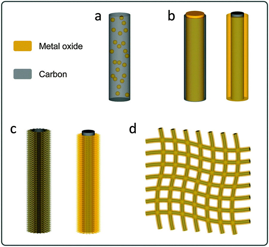 | ||
| Scheme 1 Schematic illustrations of representative 1D hybrid nanostructures. (a) Metal oxide–carbon composition nanowires; (b) metal oxide–carbon core–shell nanowires (left: metal oxide core–carbon shell; right: carbon core–metal oxide shell); (c) metal oxide–carbon 1D hierarchical hybrid structures (left: carbon-coated 1D hierarchical structure; right: metal oxide building blocks on 1D carbon backbones); (d) metal oxide–carbon fiber textile hierarchical structures. | ||
2. Metal oxide–carbon composite nanowires
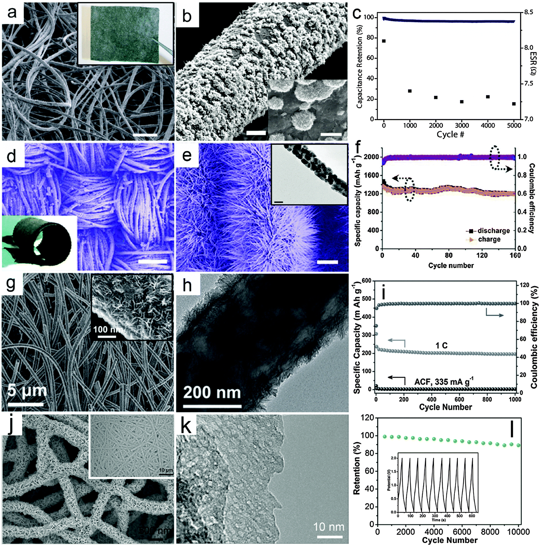
The metal oxide–carbon composite nanowires here refer to 1D nanowires composed of MO nanoparticles/nanocrystals and carbon species with random distributions. Several effective synthesis methods for constructing MO–carbon composite nanowires have been developed in the past few years, mainly including the multi-step template directed infiltration process, one-pot solution phase synthesis and the electrospinning assisted process. Specifically, the multi-step template directed infiltration process involves the post-loading of MO nanoparticles into pre-synthesized 1D carbon nanostructures (mostly hollow nanotubes) through different methods based on the penetration strategy.61–64 For example, Müllen and co-workers61 developed a three-step anodic alumina oxide (AAO) template assisted procedure to construct Co3O4–carbon composite nanowires, as shown in Fig. 1a. In their work, the pre-synthesized metal–polymer precursor, i.e., dicobalt hexacarbonyl complex is filled into the nanochannels of the AAO membrane, followed by an annealing process to convert the cobalt–polymer precursor into the cobalt–carbon composite. Finally the Co3O4–carbon composite nanowires are obtained after the removal of the AAO membrane using concentrated NaOH solution. Fig. 1b gives a typical transmission electron microscopy (TEM) image of the Co3O4–carbon composite nanowires, which clearly shows that small Co3O4 nanocrystals (inset of Fig. 1b) are uniformly distributed in the carbon matrix. The as-synthesized composite nanowires are evaluated as electrode materials for ECs, and exhibit remarkable cycling performance and improved rate capability, as shown in Fig. 1c. Despite the significant enhancement achieved by such MO–carbon composite nanowires, the limitation of this method is also obvious. Specifically, the use of the AAO template substantially increases the cost and hampers large-scale production, while the multi-step synthesis procedure is also quite time-consuming. These two drawbacks could make such a strategy less attractive for practical applications.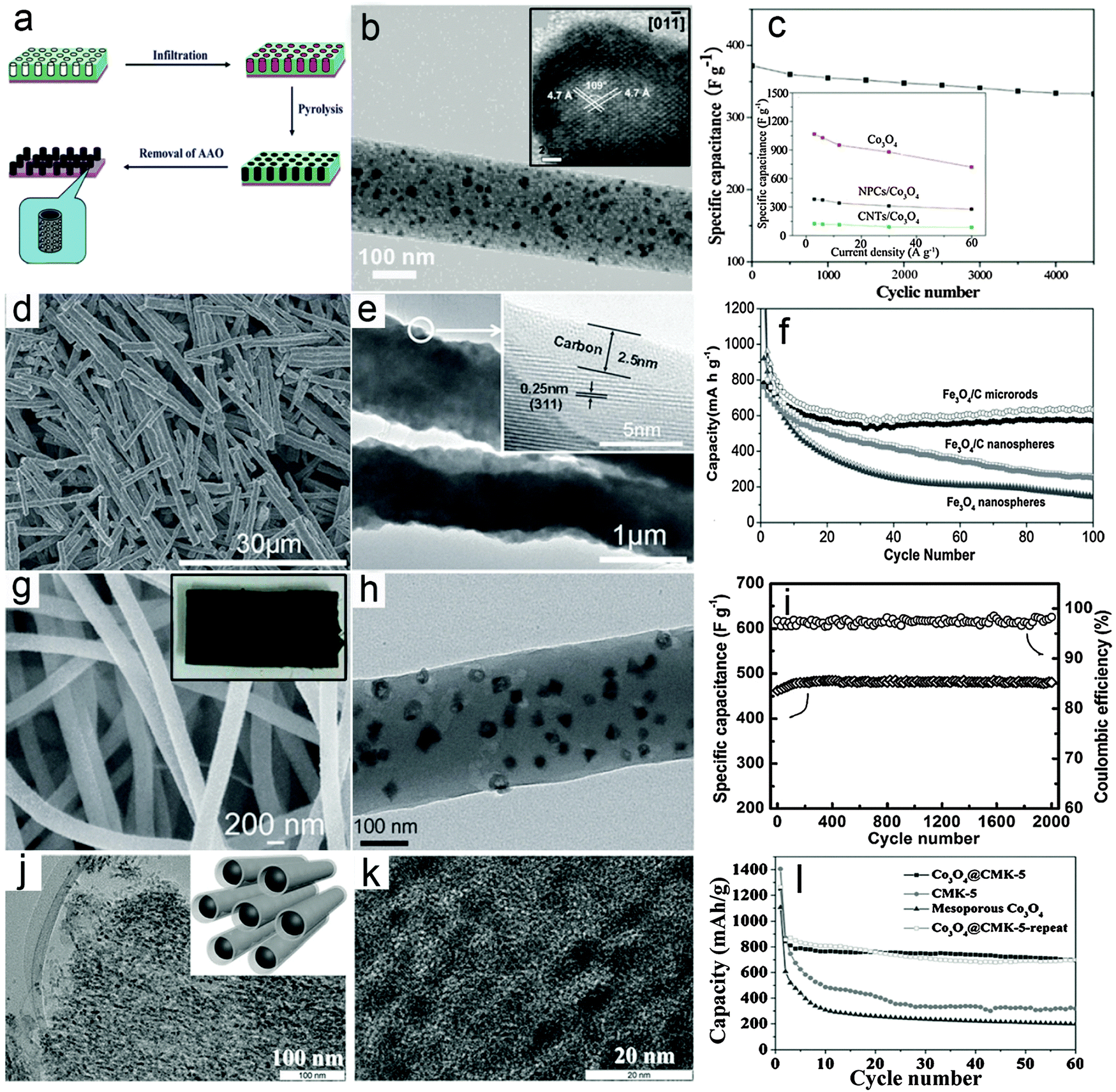 | ||
| Fig. 1 Representative metal oxide–carbon composite nanowires. (a–c) Co3O4–carbon composite nanowires: (a) a schematic illustration of the synthesis procedures, (b) TEM and HRTEM (inset) images, and (c) cycling performance as an electrode material for ECs. Reprinted with permission from ref. 61. Copyright 2010 American Chemical Society (ACS). (d–f) Fe3O4–carbon composite nanowires: (d and e) FESEM and TEM images, (f) cycling performance as an anode for LIBs. Reprinted with permission from ref. 65. Copyright 2014 Wiley. (g–i) Co3O4–carbon composite nanowires: (g) FESEM image (inset: photograph of the composite nanowire film), (h) TEM image, (i) cycling stability under a charge/discharge current density of 4 A g−1 and the corresponding Coulombic efficiency as an electrode material for ECs. Reprinted with permission from ref. 73. Copyright 2013 Wiley. (j–l) Co3O4–carbon nanotube arrays: (j) low-magnification (inset: scheme of the structure) and (k) high-magnification TEM images, and (l) cycling performance at a current density of 100 mA g−1 as an anode material for LIBs. Reprinted with permission from ref. 77. Copyright 2015 Wiley. | ||
Recently, a template-free one-pot hydrothermal method has been developed to synthesize a rod-like Fe3O4–carbon composite (short nanowires) using glucose as the carbon source under the assistance of an external magnetic field.65Fig. 1d gives a typical field-emission scanning electron microscopy (FESEM) image which clearly indicates the 1D feature of the products. The TEM image shown in Fig. 1e provides direct evidence that a thin layer of carbon is coated on the surface of the Fe3O4 nanoparticles, which serve as building blocks to form the rod-like Fe3O4–carbon composite. The use of an external magnetic field during the synthesis is a critical prerequisite for the formation of the Fe3O4–carbon 1D structure since only isolated nanoparticles can be obtained without the external magnetic field. The lithium storage performance of the rod-like Fe3O4–carbon composite as a negative electrode in LIBs is investigated and shown in Fig. 1f. As can be seen, the capacity of the rod-like Fe3O4–carbon composite gradually decreases in the first 30 cycles and then becomes stable until at least 100 cycles under a charge/discharge current density of 200 mA g−1. Comparatively, the Fe3O4–carbon composite nanospheres and Fe3O4 nanoparticles exhibit much worse cycling performance with constantly decreasing capacity upon cycling. The enhanced lithium storage performance could be contributed by both the 1D feature and the hybrid structure of the rod-like Fe3O4–carbon composite, which could facilitate the charge transport and better withstand the large volume variation during the lithium insertion/de-insertion reaction. Moreover, this one-pot and template-free method is featured by simplicity and low cost, which could benefit large-scale production. However, such a strategy is only effective for certain materials with ferromagnetic properties so that the growth direction could be controlled by the magnetic interaction between the MO nanoparticles and the external magnetic field, which would prevent the use of this method for synthesis of other MOs.
The electrospinning process, which was first applied to synthesize polymer fibers on the micro-/nano-scale in the early 1990s by Reneker,66 has gained substantial attention due to its appealing features of large-scale production and versatility.67 Recently, electrospinning has been widely applied to synthesize various MO–carbon composite nanowires.68–73 For example, we recently reported the construction of Co3O4 hollow nanoparticle (HNP)–carbon composite nanowires through the electrospinning method coupled with a post annealing procedure.73Fig. 1g shows a typical FESEM image of the Co3O4 HNP–carbon composite nanowires, indicating the large quantity production and high uniformity. Interestingly, it is found that the high-quality composite nanowires can easily form 3D self-supported films (inset of Fig. 1g), which could act as binder-free electrodes for energy storage applications. A typical TEM image shown in Fig. 1h clearly demonstrates that small and uniform Co3O4 HNPs are uniformly distributed in the CNFs. The supercapacitive performance of the Co3O4 HNP–carbon composite nanowire films was investigated and the results shown in Fig. 1i indicate that the cycling performance is substantially enhanced with almost 100% capacitance retention for 2000 cycles. This could be attributed to the high quality of the composite nanowires, which enables high robustness and fast electron/ion transport during the electrochemical process even without the use of any ancillary components (i.e., binders and conductive additives) when applied as electrodes for ECs. Moreover, many advantages of such electrospinning methods, including high productivity, low cost and generality, are highly attractive for possible applications.70,71,74,75 Nevertheless, the relatively low loading mass of electroactive MOs in the composite nanowires, which lowers the overall energy/power density of the electrodes, would be one major drawback to be tackled. Therefore, more advanced techniques as well as further optimization of the architectures of 1D MO–carbon hybrid nanostructures are required.
To address the drawbacks of conventional composite nanowires, modifications and improvements of existing synthesis strategies have also been developed. For example, a modified electrospinning method has been recently employed to fabricate various 1D oxide–carbon composites with complex architectures.76 Another study reported the synthesis of 1D composite nanostructures using a hard-template method, in which mesoporous silica (SBA-15) particles are subsequently infiltrated with carbon and cobalt precursors.77 The multi-step nanocasting method eventually produces Co3O4 nanoparticles embedded in carbon nanotube arrays (CMK-5) as shown in Fig. 1j. The small confined space in mesoporous silica prevents the aggregation of metal oxide nanoparticles even at a high loading of up to 70 wt% (Fig. 1k). In addition, the carbon nanotube arrays exhibit an interconnected conducting network and open mesopores between the nanotubes, allowing fast transport of charges and buffering the volume change during electrochemical processes. As expected, the Co3O4 nanoparticles embedded in carbon nanotube arrays (Co3O4@CMK-5) exhibit stable cycling stability with a high reversible capacity of about 700 mA h g−1 at 100 mA g−1 (Fig. 1l). Compared with conventional composite nanowires, the configuration and arrangement of metal oxides and carbon in the above-mentioned 1D composites are more complex and generally possess certain ordered nanostructures (e.g., core–shell or hollow structure), which resemble other 1D hybrid nanostructures discussed in the following sections to some extent.
3. Metal oxide–carbon core–shell nanowires
Compared with composite nanowires with a relatively random distribution of different components, MO–carbon hybrid 1D nanostructures with a well-defined core–shell configuration might enable better electron and ion transport.54 For core–shell nanowires, there are two basic configurations, i.e., MO nanowires as core materials and carbon species decorated outside the surface of MOs as shell layers; and conversely, MOs as the shell materials on the surface of 1D carbon nanostructures (e.g., CNTs and CNFs). The fabrication of core–shell nanowires is relatively less developed compared with composite nanowires, probably due to the lack of appropriate synthesis strategies.Recently, advances in synthesis chemistry and material design have enabled the synthesis of relevant structures. For example, Mai and co-workers reported a one-pot hydrothermal process to synthesize graphene-wrapped V3O7 nanowires through an “oriented assembly” and “self-scroll” strategy.78 As can be seen in Fig. 2a, 1D structures on a large scale are formed with lengths up to tens of micrometers. The V3O7–G core–shell nanowires are revealed in the TEM image (Fig. 2b). It is clearly indicated that one to several nanowires are wrapped with several layers of graphene driven by the formation of covalent bonds between rGO and V3O7 nanowires. The V3O7–G core–shell nanowires are evaluated as cathode materials for LIBs and compared to pure V3O7 nanowires and the V3O7–carbon mixture, as shown in Fig. 2c. Obviously, both the cycling performance and specific capacity of the V3O7–G core–shell nanowire electrode are notably improved, which demonstrates the benefits of the core–shell architecture. Specifically, it is argued that the outside layer of G wrapping might enhance the electrical conductivity and mechanical robustness of the inner electroactive V3O7 nanowires. Another advantage of this method lies in the simplicity of such a facile template-free and one-pot approach, which could be suitable for large-scale and cost-effective synthesis. However, further extending this method to other MOs might encounter certain difficulties, especially for MOs that could hardly grow into nanowires under hydrothermal conditions. Yu and co-workers demonstrated a general method to construct MO–G core–shell nanowires through post wrapping of GO on pre-synthesized MO nanowires, followed by the reduction of GO to G by hydrazine solution.79 In order to obtain uniform wrapping, pretreatment of the MO nanowire surface is necessary to strengthen the interaction between MO nanowires and GO, which is the driving force to form the core–shell assembly. Fig. 2d shows the Fe2O3–G core–shell nanowires with a large aspect ratio, where the 1D structure of Fe2O3 can be well retained after the G wrapping. The core–shell configuration is clearly indicated in the magnified FESEM image as well as the TEM image, as shown in Fig. 2e. The thickness of the outside graphene layer is around 3 nm estimated from the TEM image shown in Fig. 2e. A comparative study of the lithium storage properties of the Fe2O3–G core–shell nanowires and pure Fe2O3 nanowires (Fig. 2f) indicates that the core–shell composite nanowires exhibit both high specific capacity and much improved cycling stability. The most attractive feature of this method lies in its generality, which could be extended to obtain many other MO–G core–shell nanowires in principle, although the pre-synthesis and surface functionalization of the MO nanowires complicate the synthesis to some extent. Moreover, the control over the outer G wrapping layer might be relatively poor for the thickness and the interaction strength between GO and the metal oxide surface. There are also other methods to form MO–carbon core–shell nanowires, in which the pre-synthesis of MO nanowires is generally one of the necessary prerequisites.80–84 A recent study further introduced carbon coating on both the inner and outer surfaces of Fe3O4 nanotubes, which substantially improves the specific capacity compared to uncoated or single-layer coated counterparts.85 Generally speaking, the outside carbon layer would provide two major beneficial effects for the lithium storage properties of MO–carbon core–shell nanowires. First, it could improve the mechanical strength of the MO core nanowires and alleviate the stress strain derived from the volume change during the lithium insertion/dis-insertion process. Second, carbon species could help to modify the poor electrical conductivity of MOs, which facilitates the electron transfer and further contributes to the cycling performance enhancement. In addition, the outer carbon shell might also help to form a stable solid electrolyte interface (SEI) layer, thus eliminating undesirable side reactions. One concern for this structure is that the outside carbon coating could possibly block the transfer of ions which usually need to pass through the external carbon layer to the inner electro-active MOs.
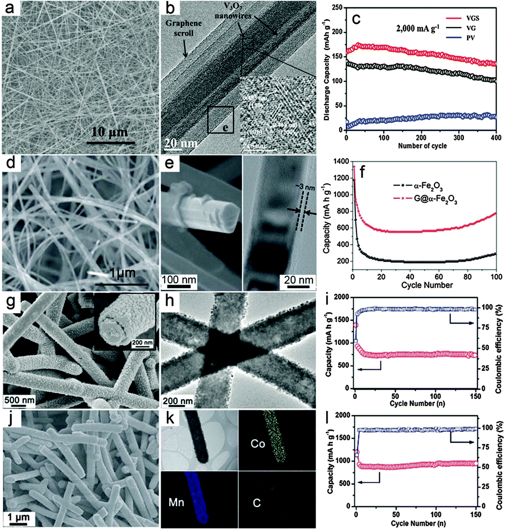 | ||
| Fig. 2 Representative metal oxide–carbon core–shell nanowires. (a–c) V3O7–graphene core–shell nanowires: (a) FESEM image, (b) TEM image and (c) cycling performance as a cathode for LIBs. Reprinted with permission from ref. 78. Copyright 2010 ACS. (d–f) Fe2O3–graphene core–shell nanowires: (d and e) FESEM and TEM images, (f) cycling performance as an anode for LIBs. Reprinted with permission from ref. 79. Copyright 2011 the Royal Society of Chemistry (RSC). (g–i) CNF–MnO core–shell nanowires: (g and h) FESEM and TEM images, (i) cycling stability under a current density of 200 mA g−1 and the corresponding Coulombic efficiency as an anode for LIBs. (j–l) CNF–CoMn2O4 core–shell nanowires: (j) FESEM image, (k) TEM image and the elemental mapping results, (l) cycling stability under a current density of 200 mA g−1 and the corresponding Coulombic efficiency as an anode for LIBs. Reprinted with permission from ref. 88. Copyright 2013 RSC. | ||
Compared with the above-discussed core–shell nanowires with an MO core and carbon shell, the inverse structure obtained by anchoring the MO shell on the surface of carbon nanowire backbone has also drawn considerable attention. Several 1D carbon materials, such as CNTs and CNFs can be used to prepare such core–shell hybrid nanowires.86,87 Very recently, we developed a general CNF template assisted two-step method for the synthesis of CNF–MO core–shell nanowires.88 In the first step, hydrothermally synthesized carbonaceous nanofibers with abundant functional groups are dispersed into the reaction medium, i.e., ethylene glycol dissolved with metal acetate precursors as the reaction precursor solution, to obtain CNF–metal–glycolate precipitates. The final CNF–MO core–shell nanowires can be easily obtained by annealing the CNF–metal–glycolate precursor nanowires under nitrogen gas protection. In this method, both simple MOs such as MnO and mixed MOs such as CoMn2O4 could be decorated on the surface of CNFs to form the CNF–MO core–shell structure by simply adjusting the metal precursors. Fig. 2g shows a typical FESEM image of the CNF–MnO core–shell nanowires with high uniformity. The magnified FESEM image (inset in Fig. 2g) clearly indicates the core–shell configuration with the outer MO layer fully covering the surface of the inner CNF. Importantly, the TEM image (Fig. 2h) shows that there is no notable gap between the MO shell and the CNF core, which demonstrates the strong coupling effect between these two components. Due to the high quality of the core–shell nanowires, the cycling performance of the CNF–MnO core–shell nanowires is substantially improved compared with other MnO nanostructures and MnO–carbon hybrid structures,89–91 as shown in Fig. 2i. Using the same procedures, CNF–CoMn2O4 core–shell nanowires can also be prepared as shown in Fig. 2j. The elemental mapping results given in Fig. 2k provide direct evidence for the formation of the ternary oxide CoMn2O4 shell on the CNF surface to form the core–shell structure. When evaluated as anode materials for LIBs, the CNF–CoMn2O4 core–shell nanowires show superior cycling stability and high specific capacity compared with previously reported CoMn2O4 nanostructures.40,92,93 as depicted in Fig. 2l. The enhanced lithium storage performance is highly dependent on the appealing features of the core–shell structure. First, the CNF backbone is sufficiently robust to maintain the integrity of the electrode film and alleviate the strain during the lithium insertion/extraction process. Second, the strong coupling effect could effectively prohibit the aggregation of the MO nanocrystals or detachment from the CNFs during cycling. Third, the CNFs would enable a faster electron transfer process without blocking the ion diffusion due to their high electrical conductivity. This method is quite general to fabricate core–shell nanowires with various simple and mixed MOs, and might be applicable to other carbonaceous supports. However, it would be difficult to incorporate materials that require post-annealing in an oxidative environment. Moreover, further modifications of the structure and composition of the core–shell nanowires would be necessary to achieve optimal performance, such as maximizing the mass fraction of active materials without degrading the performance and the use of other carbon supports with low-cost and high electrical conductivity.
4. Metal oxide–carbon one-dimensional hierarchical nanostructures
Hierarchical nanostructures with multi-level architectures have been broadly investigated for various applications including electrochemical energy storage devices.94–97 It is demonstrated that the complex hierarchy of the nanostructures would allow better control over the physical and chemical properties of the materials to achieve desirable performance. The MO–carbon 1D hierarchical nanostructures could be generally summarized into three main different configurations: (i) carbon coating onto pre-synthesized 1D hierarchical nanostructures consisting of nanoscale building blocks, such as nanorods or nanosheets; (ii) growth of nanoscale building blocks on 1D carbon backbones such as CNTs and CNFs to form 1D hierarchical structures; (iii) carbon coated nanostructure building blocks grown on 1D carbon backbones.There have been some reports recently on synthesis of hierarchical MO nanostructures.98–104 For example, our group reported the construction of hierarchical tubular structures consisting of Fe2O3 nanorods through a redox etching process using MnO2 nanorod arrays on Ti foil as the template.105 Fe3+ ions produced by oxidation of Fe2+ by MnO2 in an acidic environment precipitate as Fe(OH)3 on the surface of MnO2 nanorods. Along with the depletion of the MnO2 template, hierarchical tubular structures of Fe(OH)3 are formed and are further converted to Fe2O3 after annealing in air. A thin layer of carbon is then coated onto the Fe2O3 nanorods to form a Fe2O3@carbon 1D hierarchical tubular structure. As shown in Fig. 3a, the 1D hierarchical tubular structure is constructed by numerous needle-like fine nanorods pointing outwards, and the structure can be well retained after carbon coating. The TEM image in Fig. 3b provides evidence of its hollow character while the carbon layer uniformly covers the surface of Fe2O3 nanorods with a small thickness of about 3 nm (inset of Fig. 3b). Benefitting from the hierarchical structure and carbon coating, the Fe2O3@C 1D hierarchical tubular structure exhibits excellent cycling stability when evaluated as a negative electrode for LIBs, as shown in Fig. 3c, with a high reversible capacity of over 1100 mA h g−1 at a current density of 200 mA g−1.
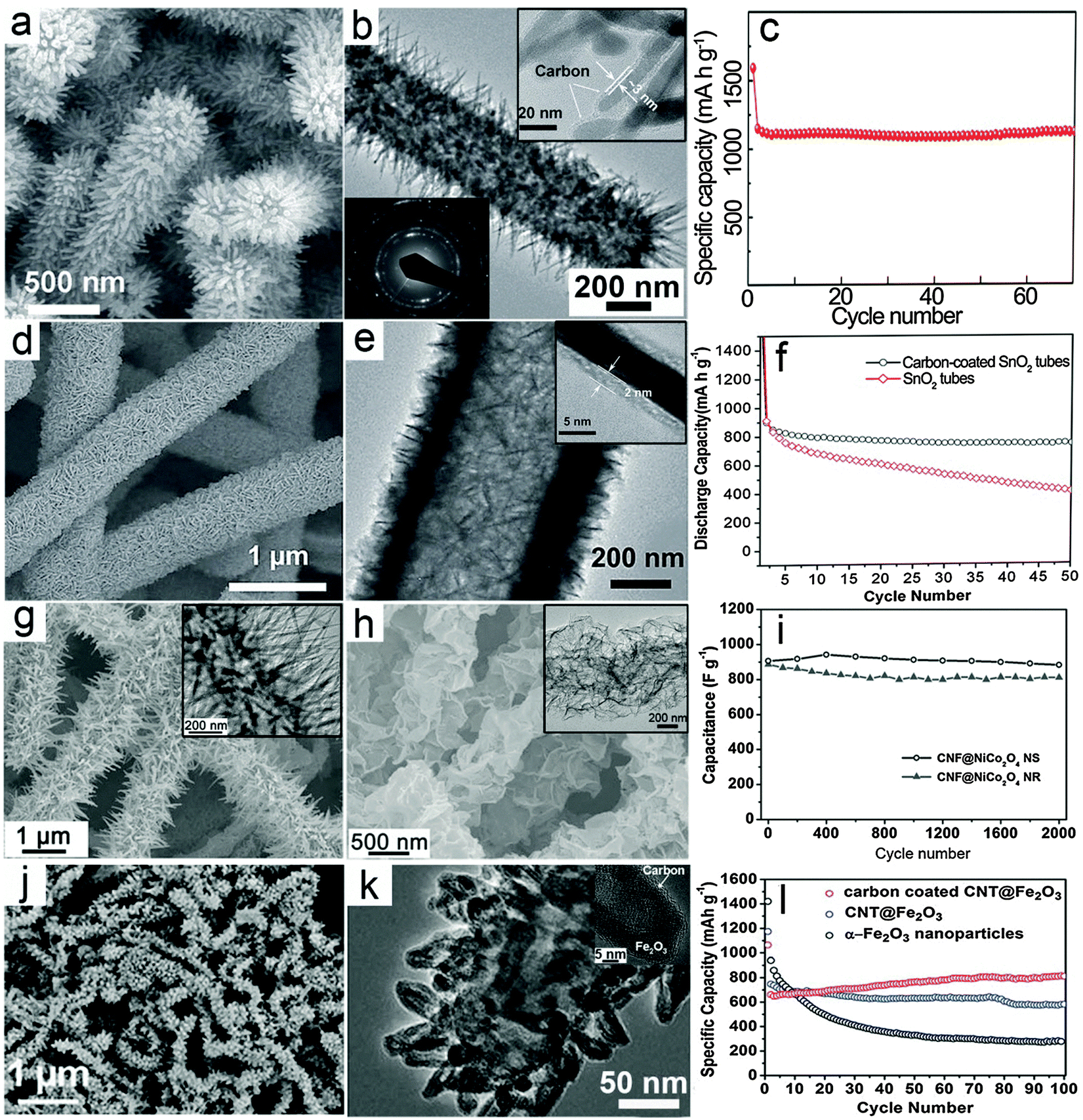 | ||
| Fig. 3 Representative metal oxide–carbon 1D hierarchical hybrid structures. (a–c) Fe2O3–carbon hierarchical tubular structures consisting of nanorods: (a) FESEM image, (b) TEM image, and (c) cycling stability as an anode for LIBs. Reprinted with permission from ref. 105. Copyright 2014 Wiley. (d–f) SnO2@C hierarchical tubular structures: (d and e) FESEM and TEM images, (f) cycling performance as an anode for LIBs. Reprinted with permission from ref. 109. Copyright 2013 Wiley. (g–i) CNF@NiCo2O4 NR and CNF@NiCo2O4 NS hierarchical 1D hybrid structures: (g) FESEM and TEM (inset) images of CNF@NiCo2O4 NR, (h) FESEM and TEM (inset) images of CNF@NiCo2O4 NS, (i) comparison of cycling performance for CNF@NiCo2O4 NR and CNF@NiCo2O4 NS as electrode materials for ECs under a current density of 2 A g−1. Reprinted with permission from ref. 112. Copyright 2013 Nature Publishing Group. (j–l) Carbon-coated CNT@Fe2O3 hierarchical 1D structures: (j) FESEM image, (k) TEM image, (l) comparison of cycling stability for carbon-coated CNT@Fe2O3, CNT@Fe2O3 and Fe2O3 nanoparticles as anode materials for LIBs. Reprinted with permission from ref. 113. Copyright 2011 RSC. | ||
Different from 1D nanostructures, 2D nanostructures called nanosheets possess features like a large planar size and small thickness. Generally, the large planar size could lower the internal resistance, which facilitates the electron transfer process.34,106–108 Moreover, the small thickness preserves the advantages of nanostructured materials such as the short ion transport path and large surface area. Therefore, 1D hierarchical structures consisting of 2D nanosheets could possess combined advantages. With the assistance of carbon coating, it is reasonable to expect enhanced electrochemical performance. As an example, our group reported a SnO2 hierarchical tubular structure composed of carbon coated ultrathin nanosheets through a multi-step template assisted method.109 The synthesis procedure could be described by the following steps: (i) hydrothermally synthesized CNFs are uniformly coated with ultrathin SnO2 nanosheets through a simple hydrothermal method; (ii) a pure SnO2 hierarchical tubular structure is formed by annealing in air to remove the CNF template; (iii) thin carbon layer coating is performed to form the SnO2@C hierarchical tubular structure. As shown in Fig. 3d, hierarchical tubular structures constructed from ultrathin SnO2 nanosheets can be obtained after the carbon coating. The hollow feature is disclosed by the TEM image (Fig. 3e), while the thickness of the carbon layer is revealed by the magnified TEM image (inset of Fig. 3e) to be about 2 nm. With carbon coating, the cycling stability of the structure for lithium storage is significantly enhanced as shown in Fig. 3f.
In previous discussions, it has been demonstrated that carbon–MO core–shell nanowires exhibit excellent electrochemical performance compared with many other nanostructures. It is anticipated that complex hierarchical core–shell structures composed of nanoscale building blocks such as nanorods or nanosheets on 1D carbon backbones might bring additional benefits.110,111 Our group recently developed a simple low-temperature solution method followed by post-annealing for the controllable synthesis of 1D hierarchical nanostructures constructed from NiCo2O4 nanorods (NRs) or ultrathin nanosheets (NSs) onto CNF backbones.112 In this method, the morphology of the nanoscale NiCo2O4 building blocks could be easily controlled by the reaction additives. Using urea as an alkaline source will produce nanorods, while using hexamethylenetetramine forms ultrathin nanosheets. Typical morphologies of the CNF@NiCo2O4 NR and CNF@NiCo2O4 NS hierarchical hybrid nanostructures are shown in Fig. 3g and h, respectively. These two different 1D hierarchical structures are investigated and compared as electrode materials for ECs to demonstrate the possible effects of morphology on the electrochemical properties. As shown in Fig. 3i, it is evident that the CNF@NiCo2O4 NSs hierarchical structure delivers higher capacitance and exhibits better cycling performance compared to CNF@NiCo2O4 NRs.
The above-mentioned MO–carbon 1D hierarchical nanostructures have been shown to exhibit enhanced electrochemical performance. It would be highly desirable yet challenging to combine different design rationales and construct 1D hierarchical nanostructures with higher complexity. As an example, we reported the synthesis of a novel 1D hierarchical nanostructure by assembling carbon coated Fe2O3 hollow nanohorns on CNT backbones.113Fig. 3j gives an overview of the morphology of the carbon-coated CNT@Fe2O3 hierarchical nanostructure, showing that the horn-like Fe2O3 nanoparticles uniformly cover the CNT backbones. The hollow feature of the Fe2O3 building blocks and evidence of carbon coating on the surface of these Fe2O3 nanohorns can be clearly observed through magnified TEM images (Fig. 3k and inset). In this configuration, the external carbon coating reinforces the mechanical strength of the hollow nanohorns and the CNT backbones serve as a “highway” for electron transport, both of which contribute to the enhancement of the electrochemical properties. As a result, the carbon-coated CNT@Fe2O3 hierarchical 1D nanostructure exhibits excellent cycling performance with slightly increased reversible capacity over 100 cycles as shown in Fig. 3l, which is obviously superior to pure Fe2O3 nanoparticles and a similar CNT@Fe2O3 hierarchical 1D nanostructure without the external carbon nanocoating. Therefore, despite the challenges in synthesis, the construction of complex hierarchical 1D nanostructures might bring great promise to further optimize the electrochemical performance.
5. Metal oxide–carbon fiber textile hierarchical structures for flexible energy storage devices
Flexible power sources have attracted rapidly growing interest because of the increasing demand for flexible electronic devices, such as roll-up displays and wearable devices.114–120 In a flexible electrochemical energy storage device, a current collector with high flexibility is one of the most important components. Thin metal foil has been used as a flexible substrate for the deposition of nanorod arrays as integrated electrodes.121 However, it is not easy to achieve high areal active mass loading and high mechanical robustness on planar substrate-based electrodes. Alternatively, carbon fiber textiles, such as carbon cloths and CNT/CNF films that are typically assembled from 1D carbon materials have recently been broadly investigated as flexible and light weight substrates for integrated electrodes. These textiles are usually composed of highly entangled CNTs/CNFs. This offers a high surface area for the direct anchoring or growth of nanostructured electroactive MOs. Besides high flexibility, this type of electrode shows several additional benefits. First, the 3D interconnected conductive framework significantly promotes the electron transport compared with conventional nanocomposite films made from powders. Second, the carbon textiles serve as robust supports for MO nanostructures, which prevents the possible structural deformation and/or aggregation of the nanoscale building blocks. In principle, auxiliary components such as conductive additives and polymer binders can be excluded, which simplifies the fabrication process and increases the energy density of the overall electrodes.In recent years, enormous progress has been made in controlled growth of various MO nanostructures on flexible carbon substrates.122–128 In this section, we will highlight some recent advances in integrated electrodes composed of MO nanostructures and carbon fiber-based flexible substrates. Recently, Yu and co-workers developed a solution-based method to prepare a graphene/MnO2/textile fiber hierarchical structure.129 Graphene nanosheets are first coated on the porous textile to serve as the conductive 3D frameworks, as shown in the inset of Fig. 4a, followed by electrodeposition of MnO2 onto the surface of the fibers. Typical FESEM images with different magnifications (Fig. 4a and b) indicate that large scale and uniform MnO2 flower-like nanostructures are grown on the graphene decorated textile fibers. In order to investigate the supercapacitive performance of the integrated electrode, an asymmetric EC device is built using graphene/MnO2/textile as the positive electrode and CNT/textile as the negative electrode. Fig. 4c shows the cycling performance of the device with a current density of 2.2 A g−1, which achieves a high capacitance retention of ∼95% after 5000 cycles.
 | ||
| Fig. 4 Representative metal oxide–carbon fiber textile hierarchical structures. (a–c) Graphene/MnO2/fabric textile: (a) FESEM image (inset is a photograph of the graphene decorated fabric textile, scale bar is 200 μm), (b) FESEM image (scale bars are 5 and 1 μm for main figure and inset respectively) and (c) cycling performance for the full EC device consisting of a CNT/fabric textile negative electrode and a graphene/MnO2/fabric textile positive electrode. Reprinted with permission from ref. 129. Copyright 2011 ACS. (d–f) ZnCo2O4 nanowires/carbon cloth: (d) an overview of the ZnCo2O4 nanowires/carbon cloth (scale bar is 200 μm; the inset is a photograph of the ZnCo2O4 nanowires/carbon cloth), (e) FESEM image of ZnCo2O4 nanowires/carbon cloth (the inset is a TEM image of an individual ZnCo2O4 nanowire, scale bars are 1 μm and 50 nm in the main figure and inset respectively), (f) cycling performance as an anode for LIBs under a current density of 200 mA g−1. Reprinted with permission from ref. 130. Copyright 2012 ACS. (g–i) TiO2-B NSs/ACF: (g) FESEM images with different magnifications, (h) TEM image, (i) cycling performance under a current density of 1 C (1 C = 335 mA g−1) as an anode for LIBs. Reprinted with permission from ref. 132. Copyright 2012 Wiley. (j–l) Porous V2O5 nanosheets/ECF: (j) FESEM image (inset: low-magnification image) of V2O5 nanosheets on the ECF, (k) TEM image of porous V2O5 nanosheets, and (j) cycling performance (inset: charge–discharge voltage curves) of flexible V2O5–ECF//ECF asymmetric solid-state ECs. Reprinted with permission from ref. 133. Copyright 2015 Wiley. | ||
In addition, Shen and co-workers successfully constructed a 3D hierarchical structure by growing ZnCo2O4 nanowire arrays on carbon cloth through a simple hydrothermal route, followed by a thermal annealing treatment in air.130 A typical FESEM image in Fig. 4d clearly shows the textile architecture of the carbon cloth consisting of carbon microfibers after the growth of ZnCo2O4 nanowire arrays. The flexibility of the integrated electrode is remarkable, as demonstrated by rolling the ZnCo2O4 nanowires/carbon cloth (inset of Fig. 4d). The ZnCo2O4 nanowire arrays can be clearly observed in the magnified FESEM image in Fig. 4e, which fully cover the surface of the carbon fibers. The TEM image in the inset of Fig. 4e shows that each nanowire is polycrystalline and composed of small nanocrystals. The ZnCo2O4 nanowire/carbon cloth integrated electrode is then investigated as a negative electrode for LIBs, as shown in Fig. 4f. The cycling performance of this nanowire-based hierarchical electrode is excellent with a high capacity retention of 99% after 160 cycles under a current density of 200 mA g−1. Moreover, a full battery is fabricated to further demonstrate the high performance of the ZnCo2O4 nanowire/carbon cloth electrode by using commercial LiCoO2 as the cathode.
The concept of using MO/carbon fabric as the integrated electrode is rather generic, and can be applied to many other MOs with diverse nanostructures. Besides carbon cloth, carbon textiles assembled from electrospun CNFs have also drawn considerable attention, which might offer better control over the micro-/nanostructure of the integrated carbon substrates. MOs can also be incorporated into the CNFs during the electrospinning process.131 However, the relatively low loading of MOs in the CNFs would hinder the overall performance of the electrodes. Thus, post-deposition or growth of nanostructured MOs on pre-synthesized CNF textiles has been widely adopted. For a particular system, difficulties may arise from the suitable chemistry involved and control of the crystal phase and structure of electroactive materials. For example, we demonstrated that integrated electrodes based on TiO2-B NSs and activated carbon fabric (ACF) films function well as long lifespan and high-rate anodes for LIBs.132 In this work, TiO2-B NSs are grown on ACF films composed of electrospun CNFs by controllable hydrolysis and condensation of the titanium precursor at a relatively low temperature of 150 °C followed by thermal annealing in air. Fig. 4g gives a typical FESEM image of this TiO2-B NSs/ACF hierarchical structure. The surface layer is composed of 2D ultrathin NSs as clearly revealed by high-magnification FESEM and TEM images (inset of Fig. 4g and h). The TiO2-B NSs construct a porous layer of ∼35 nm in thickness on the surface of the highly conducting CNFs, which are fully accessible to the electrolyte when applied as an integrated electrode for LIBs. As shown in Fig. 4i, the TiO2-B NSs/ACF electrode exhibits an outstanding long-cycle life of 1000 cycles with only slight capacity degradation. The remarkable performance originates from the appropriate engineering of nanostructured and electroactive materials. Such flexible integrated electrodes hold some promise for practical application in flexible LIBs.
Similar strategies can also be extended to other metal oxides and electrochemical energy storage devices. In recent work, porous V2O5 nanosheets were grown on an electrospun carbon fiber (ECF) substrate by using a solvothermal method followed by annealing.133 As shown in Fig. 4j, the V2O5 nanosheets are densely and vertically aligned on the ECF, forming an interconnected and porous coating layer. The nanosheets possess a porous texture (Fig. 4k), which is generated during the annealing process. In such an architecture, the intimate and robust contact between the V2O5 nanosheets and the ECF offers fast electronic transport and high structural stability, while the porous and interconnected V2O5 nanosheets ensure a large electrochemical active surface and rapid ionic transport even with high mass loading of active V2O5. When tested with a three-electrode setup in an aqueous electrolyte, the V2O5–ECF electrode delivers a specific capacitance of 408 F g−1 at 1 A g−1. The V2O5–ECF electrode is further coupled with another ECF electrode and assembled into flexible asymmetric quasi-solid-state ECs, which manifests a high energy density of 22.4 W h kg−1 at a power density of 1500 W kg−1 with high cycling stability over 10![[thin space (1/6-em)]](https://www.rsc.org/images/entities/char_2009.gif) 000 cycles (Fig. 4l).
000 cycles (Fig. 4l).
6. Conclusions and outlook
In this mini review, we summarize and highlight some recent advances on 1D metal oxide (MO)–carbon hybrid nanostructures, which are categorized into four sections according to their different configurations, namely MO–carbon composite nanowires, MO–carbon core–shell nanowires, MO–carbon hierarchical 1D nanostructures, and MO–carbon textile hierarchical structures for flexible devices. The structural features, advantages and disadvantages of each type of MO–carbon 1D hybrid nanostructure, as well as their electrochemical properties and potential applications have been briefly discussed. A summary and comparison of the MO–carbon 1D hybrid nanostructures highlighted in this mini review are given in Table 1. We aim to draw some attention to the continuous efforts in the related research fields. In addition, the possible effects of different configurations and morphologies of the hybrid structures on their electrochemical performance have also been discussed. We hope to provide some guiding rules for the future development of MO–carbon 1D hybrid nanostructures for electrochemical energy storage. One observation is that core–shell structured hybrid nanowires with 1D conducting carbon backbones as the core material and electroactive MOs as the shell would generally deliver better electrochemical performance compared with MO–carbon composite nanowires. Moreover, the morphology of the MO shell could also play an important role in the electrochemical performance of the hybrid nanostructures. According to the current results in the literature, two-dimensional (2D) nanosheets might be promising candidates as the building blocks for MO shells rather than nanoparticles or nanowires. In particular, nanosheets with ultrathin thicknesses and/or porous features could substantially facilitate the electron and ion transport processes, and possess strong mechanical robustness at the same time. In addition, enhanced electrochemical performance could also be achieved by using complex architectures that incorporate several design rationales, such as an extra carbon coating layer on the hierarchical MO shells. However, it would be immature to conclude that a particular structure or morphology is most beneficial for electrochemical energy storage in view of the high complexity of electrochemical devices.| Category | Structure | Chemical composition | Synthesis method | Electrochemical performance | Featuresa | ||
|---|---|---|---|---|---|---|---|
| Syn. cost | EC activity | MO content | |||||
| a Features of the 1D hybrid nanostructures highly depend on the synthesis method and composition. Here, only the general situations for each category of hybrid nanostructures are discussed, including the synthesis (syn.) cost, electrochemical (EC) activity and metal oxide (MO) content in the hybrid structures. | |||||||
| Composite nanowires | MO nanoparticles in carbon matrix | Co3O4–C61 | Hard template and annealing | 382 F g−1@3 A g−1 for ECs | Low | Low | Low |
| Fe3O4–C65 | Hydrothermal with external magnetic field | ∼650 mA h g−1@200 mA g−1 for LIBs | |||||
| Co3O4 HNPs–C73 | Electrospinning and annealing | 556 F g−1@1 A g−1 for ECs | |||||
| Co3O4–C77 | Multi-step hard template | ∼700 mA h g−1@100 mA g−1 for LIBs | |||||
| Core–shell nanowires | MO core–carbon shell | V3O7–G78 | One-pot hydrothermal | 321 mA h g−1@100 mA g−1 for LIBs | Moderate | Moderate | Moderate to high |
| Fe2O3–G79 | Post wrapping of G on MO | ∼780 mA h g−1@200 mA g−1 for LIBs | |||||
| Carbon core–MO shell | CNF–MO88 | Solvothermal and annealing | 870 mA h g−1@200 mA g−1 for LIBs (CNF–CoMn2O4) | ||||
| 1D hierarchical hybrid structures | Carbon-coated 1D MO hierarchical structure | Fe2O3@C105 | Template-engaged hydrothermal and annealing | ∼1100 mA h g−1@200 mA g−1 for LIBs | High | High | Moderate to high |
| SnO2@C109 | Hard template, hydrothermal and annealing | ∼700 mA h g−1@200 mA g−1 for LIBs | |||||
| MO building blocks on 1D carbon | CNF@NiCo2O4112 | Hydrothermal and annealing | ∼900 F g−1@2 A g−1 for ECs | ||||
| Carbon-coated MO on 1D carbon | Carbon-coated CNT@Fe2O3113 | Hydrothermal and annealing | ∼800 mA h g−1@500 mA g−1 for LIBs | ||||
| Fiber textile hierarchical structures | MO building block on fiber textile | G/MnO2/textile fibers129 | Electro-deposition | ∼315 F g−1@2 mV s−1 for ECs | Moderate to high | High | Low to moderate |
| ZnCo2O4/carbon cloth130 | Hydrothermal and annealing | ∼1200 mA h g−1@200 mA g−1 for LIBs | |||||
| TiO2-B/ACF132 | Solvothermal and annealing | ∼200 mA h g−1@335 mA g−1 for LIBs | |||||
| V2O5/ECF133 | Solvothermal and annealing | 408 F g−1@1 A g−1 for ECs | |||||
Despite the many advantages, it should be admitted that several drawbacks also exist in MO–carbon 1D hybrid nanostructures. The major shortcomings of these hybrid nanostructures might lie in the following aspects. First, the carbon components in the 1D MO–carbon hybrid nanostructures typically show low electrochemical activity, which would inevitably decrease the overall specific capacity/capacitance of the electrode materials compared with pure metal oxides. Second, the density of carbon is much lower than that of metal oxides. Together with the low packing density commonly observed for nanostructured materials, the volumetric power and energy densities of the electrodes would be compromised. Finally, the synthesis procedures for 1D MO–carbon hybrid structures are typically tedious and more time-/cost-consuming compared with pure metal oxide micro-/nanostructures, which would hinder the large-scale and low-cost production. Nevertheless, certain compromises would be necessary to fulfill the demands which are the critical bottlenecks for the developments of high-performance electrochemical energy storage devices. Additional challenges associated with the inherent characteristics of metal oxide active materials also exist. For example, the significant potential gap commonly observed in the charge/discharge profiles of conversion-type lithium storage materials would inevitably reduce the energy storage efficiency of the devices.15 In practical situations, enhancing the transport of electrons and ions in the electrodes by appropriately designing 1D hybrid nanostructures would effectively alleviate such issues. Optimistically, the above-mentioned challenges of 1D MO–carbon hybrid nanostructures could be partly overcome by optimizing the nanostructures and innovating the synthesis approach, where continuous efforts should be devoted.
In most reported 1D MO–carbon hybrid nanostructures, the carbon components are generally inactive or exhibit much lower capacity/capacitance during the electrochemical processes compared with the electroactive MOs, whereas they typically take up a large fraction in the hybrid structures. Thus, using light weight nanostructured carbon supports with high electronic conductivity such as high-quality graphene film/foam would be a possible solution. Addressing the compatibility between hydrophilic MOs and hydrophobic carbon supports would be another important aspect to ensure robust MO–carbon interfaces and easy hybridization between MOs and carbon components. At the same time, optimizing the porosity of hybrid nanostructures would be another effective approach towards high volumetric capacity/capacitance of the electrodes, which is indispensable for practical applications. For example, the volumetric capacity/capacitance of nanostructured electrodes based on textiles (such as carbon cloth) would be improved by excluding unnecessary ultra large pores/empty space without sacrificing the fast ionic transport. While complex 1D MO–carbon nanostructures that incorporate multiple functional components and hierarchical architectures are highly anticipated in future research, it should not be forgotten that cost-effective and scalable synthesis approaches would always be prerequisites for large-scale commercial uses.
The family of 1D MO–carbon hybrid nanostructures holds great promise for high-performance electrochemical energy storage devices, despite some remaining challenges that should be tackled with continuous research efforts. Encouragingly, 1D MO–carbon hybrid nanostructure-based electrodes with capacity/capacitance and lifespans far exceeding the commercial products have been well demonstrated by many groups. Based on either textile substrates or self-assembled films, they are also ideal candidates for flexible power sources with great demand from emerging wearable electronic gadgets. These intriguing electrode materials will likely boost the advances in electrochemical energy storage and the development of new technologies beyond conventional LIBs and ECs, which may eventually play important roles in overcoming the energy and environmental challenges of modern society.
References
- Z. Yang, J. Zhang, M. C. W. Kintner-Meyer, X. Lu, D. Choi, J. P. Lemmon and J. Liu, Chem. Rev., 2011, 111, 3577 CrossRef CAS PubMed.
- M. Armand and J. M. Tarascon, Nature, 2008, 451, 652 CrossRef CAS PubMed.
- J. R. Miller and P. Simon, Science, 2008, 321, 651 CrossRef CAS PubMed.
- B. Dunn, H. Kamath and J. M. Tarascon, Science, 2011, 334, 928 CrossRef CAS PubMed.
- P. Simon and Y. Gogotsi, Nat. Mater., 2008, 7, 845 CrossRef CAS PubMed.
- J. M. Tarascon and M. Armand, Nature, 2001, 414, 359 CrossRef CAS PubMed.
- J. B. Goodenough and K.-S. Park, J. Am. Chem. Soc., 2013, 135, 1167 CrossRef CAS PubMed.
- M. Winter and R. J. Brodd, Chem. Rev., 2004, 104, 4245 CrossRef CAS PubMed.
- N.-S. Choi, Z. Chen, S. A. Freunberger, X. Ji, Y.-K. Sun, K. Amine, G. Yushin, L. F. Nazar, J. Cho and P. G. Bruce, Angew. Chem., Int. Ed., 2012, 51, 9994 CrossRef PubMed.
- P. J. Hall, M. Mirzaeian, S. I. Fletcher, F. B. Sillars, A. J. R. Rennie, G. O. Shitta-Bey, G. Wilson, A. Cruden and R. Carter, Energy Environ. Sci., 2010, 3, 1238 CAS.
- H. Nishihara and T. Kyotani, Adv. Mater., 2012, 24, 4473 CrossRef CAS PubMed.
- L. L. Zhang and X. S. Zhao, Chem. Soc. Rev., 2009, 38, 2520 RSC.
- Y. Zhu, S. Murali, M. D. Stoller, K. J. Ganesh, W. Cai, P. J. Ferreira, A. Pirkle, R. M. Wallace, K. A. Cychosz, M. Thommes, D. Su, E. A. Stach and R. S. Ruoff, Science, 2011, 332, 1537 CrossRef CAS PubMed.
- C. Yuan, H. B. Wu, Y. Xie and X. W. Lou, Angew. Chem., Int. Ed., 2014, 53, 1488 CrossRef CAS PubMed.
- J. Cabana, L. Monconduit, D. Larcher and M. R. Palacín, Adv. Mater., 2010, 22, E170 CrossRef PubMed.
- F. M. Courtel, H. Duncan, Y. Abu-Lebdeh and I. J. Davidson, J. Mater. Chem., 2011, 21, 10206 RSC.
- T.-Y. Wei, C.-H. Chen, H.-C. Chien, S.-Y. Lu and C.-C. Hu, Adv. Mater., 2010, 22, 347 CrossRef PubMed.
- P. Poizot, S. Laruelle, S. Grugeon, L. Dupont and J. M. Tarascon, Nature, 2000, 407, 496 CrossRef PubMed.
- P. G. Bruce, B. Scrosati and J.-M. Tarascon, Angew. Chem., Int. Ed., 2008, 47, 2930 CrossRef CAS PubMed.
- A. S. Arico, P. Bruce, B. Scrosati, J. M. Tarascon and W. Van Schalkwijk, Nat. Mater., 2005, 4, 366 CrossRef CAS PubMed.
- L. W. Ji, Z. Lin, M. Alcoutlabi and X. W. Zhang, Energy Environ. Sci., 2011, 4, 2682 CAS.
- R. B. Rakhi, W. Chen, D. Cha and H. N. Alshareef, Adv. Energy Mater., 2012, 2, 381 CrossRef CAS.
- Z. Wang, L. Zhou and X. W. Lou, Adv. Mater., 2012, 24, 1903 CrossRef CAS PubMed.
- H. B. Wu, J. S. Chen, H. H. Hng and X. Wen Lou, Nanoscale, 2012, 4, 2526 RSC.
- N. P. Dasgupta, J. Sun, C. Liu, S. Brittman, S. C. Andrews, J. Lim, H. Gao, R. Yan and P. Yang, Adv. Mater., 2014, 26, 2137 CrossRef CAS PubMed.
- H.-W. Lee, P. Muralidharan, R. Ruffo, C. M. Mari, Y. Cui and D. K. Kim, Nano Lett., 2010, 10, 3852 CrossRef CAS PubMed.
- X. W. Lou, D. Deng, J. Y. Lee, J. Feng and L. A. Archer, Adv. Mater., 2008, 20, 258 CrossRef CAS.
- L. F. Shen, E. Uchaker, X. G. Zhang and G. Z. Cao, Adv. Mater., 2012, 24, 6502 CrossRef CAS PubMed.
- L. Shen, E. Uchaker, X. Zhang and G. Cao, Adv. Mater., 2012, 24, 6502 CrossRef PubMed.
- E. Hosono, T. Kudo, I. Honma, H. Matsuda and H. Zhou, Nano Lett., 2009, 9, 1045 CrossRef CAS PubMed.
- W. Tang, Y. Hou, F. Wang, L. Liu, Y. Wu and K. Zhu, Nano Lett., 2013, 13, 2036 CrossRef CAS PubMed.
- S. Liu, H. Jia, L. Han, J. Wang, P. Gao, D. Xu, J. Yang and S. Che, Adv. Mater., 2012, 24, 3201 CrossRef CAS PubMed.
- J. H. Liu, J. S. Chen, X. F. Wei, X. W. Lou and X. W. Liu, Adv. Mater., 2011, 23, 998 CrossRef CAS PubMed.
- J. Liu and X.-W. Liu, Adv. Mater., 2012, 24, 4097 CrossRef CAS PubMed.
- A. Q. Pan, H. B. Wu, L. Zhang and X. W. Lou, Energy Environ. Sci., 2013, 6, 1476 CAS.
- J. S. Chen and X. W. Lou, Small, 2013, 9, 1877 CrossRef CAS PubMed.
- J. S. Chen and X. W. Lou, Mater. Today, 2012, 15, 246 CrossRef CAS.
- X. W. Lou, L. A. Archer and Z. C. Yang, Adv. Mater., 2008, 20, 3987 CrossRef CAS.
- G. Zhang, L. Yu, H. B. Wu, H. E. Hoster and X. W. Lou, Adv. Mater., 2012, 24, 4609 CrossRef CAS PubMed.
- L. Zhou, D. Zhao and X. W. Lou, Adv. Mater., 2012, 24, 745 CrossRef CAS PubMed.
- M. H. Oh, T. Yu, S.-H. Yu, B. Lim, K.-T. Ko, M.-G. Willinger, D.-H. Seo, B. H. Kim, M. G. Cho, J.-H. Park, K. Kang, Y.-E. Sung, N. Pinna and T. Hyeon, Science, 2013, 340, 964 CrossRef CAS PubMed.
- X. Y. Lai, J. E. Halpert and D. Wang, Energy Environ. Sci., 2012, 5, 5604 CAS.
- G. Q. Zhang and X. W. Lou, Angew. Chem., Int. Ed., 2014, 53, 9041 CrossRef CAS PubMed.
- L. Zhang, H. B. Wu and X. W. Lou, Adv. Energy Mater., 2014, 4, 1300958 Search PubMed.
- Y.-G. Guo, J.-S. Hu and L.-J. Wan, Adv. Mater., 2008, 20, 2878 CrossRef CAS.
- A. e. Aricò, Nat. Mater., 2005, 4, 366 CrossRef PubMed.
- A. L. M. Reddy, S. R. Gowda, M. M. Shaijumon and P. M. Ajayan, Adv. Mater., 2012, 24, 5045 CrossRef CAS PubMed.
- G. Yu, X. Xie, L. Pan, Z. Bao and Y. Cui, Nano Energy, 2013, 2, 213 CrossRef CAS.
- L. F. Cui, Y. Yang, C. M. Hsu and Y. Cui, Nano Lett., 2009, 9, 3370 CrossRef CAS PubMed.
- R. D. Costa, F. Lodermeyer, R. Casillas and D. M. Guldi, Energy Environ. Sci., 2014, 7, 1281 CAS.
- R. D. Costa, S. Feihl, A. Kahnt, S. Gambhir, D. L. Officer, G. G. Wallace, M. I. Lucio, M. A. Herrero, E. Vázquez, Z. Syrgiannis, M. Prato and D. M. Guldi, Adv. Mater., 2013, 25, 6513 CrossRef CAS PubMed.
- X. Huang, Z. Zeng, Z. Fan, J. Liu and H. Zhang, Adv. Mater., 2012, 24, 5979 CrossRef CAS PubMed.
- Y. Sun, Q. Wu and G. Shi, Energy Environ. Sci., 2011, 4, 1113 CAS.
- F. F. Cao, Y. G. Guo and L. J. Wan, Energy Environ. Sci., 2011, 4, 1634 CAS.
- Y. Fang, B. Luo, Y. Jia, X. Li, B. Wang, Q. Song, F. Kang and L. Zhi, Adv. Mater., 2012, 24, 6348 CrossRef CAS PubMed.
- S. Han, D. Wu, S. Li, F. Zhang and X. Feng, Adv. Mater., 2014, 26, 849 CrossRef CAS PubMed.
- Y. Tang, D. Wu, S. Chen, F. Zhang, J. Jia and X. Feng, Energy Environ. Sci., 2013, 6, 2447 CAS.
- G. Zhang, B. Y. Xia, X. Wang and X. W. Lou, Adv. Mater., 2014, 26, 2408 CrossRef CAS PubMed.
- S. Ding, D. Luan, F. Y. C. Boey, J. S. Chen and X. W. Lou, Chem. Commun., 2011, 47, 7155 RSC.
- X. Cao, Z. Yin and H. Zhang, Energy Environ. Sci., 2014, 7, 1850 CAS.
- Y. Liang, M. G. Schwab, L. Zhi, E. Mugnaioli, U. Kolb, X. Feng and K. Muellen, J. Am. Chem. Soc., 2010, 132, 15030 CrossRef CAS PubMed.
- R. Hu, W. Sun, H. Liu, M. Zeng and M. Zhu, Nanoscale, 2013, 5, 11971 RSC.
- C. Chae, J. H. Kim, J. M. Kim, Y.-K. Sun and J. K. Lee, J. Mater. Chem., 2012, 22, 17870 RSC.
- W.-J. Yu, P.-X. Hou, L.-L. Zhang, F. Li, C. Liu and H.-M. Cheng, Chem. Commun., 2010, 46, 8576 RSC.
- Y. Wang, L. Zhang, X. Gao, L. Mao, Y. Hu and X. W. Lou, Small, 2014, 10, 2815 CrossRef CAS PubMed.
- J. Doshi and D. H. Reneker, J. Electrost., 1995, 35, 151 CrossRef CAS.
- S. Cavaliere, S. Subianto, I. Savych, D. J. Jones and J. Roziere, Energy Environ. Sci., 2011, 4, 4761 CAS.
- L. Wang, Y. Yu, P. C. Chen, D. W. Zhang and C. H. Chen, J. Power Sources, 2008, 183, 717 CrossRef CAS.
- L. Ji and X. Zhang, Electrochem. Commun., 2009, 11, 795 CrossRef CAS.
- P. Zhang, Z. P. Guo, Y. Huang, D. Jia and H. K. Liu, J. Power Sources, 2011, 196, 6987 CrossRef CAS.
- L. Ji, O. Toprakci, M. Alcoutlabi, Y. Yao, Y. Li, S. Zhang, B. Guo, Z. Lin and X. Zhang, ACS Appl. Mater. Interfaces, 2012, 4, 2672 CAS.
- J. Liu, K. Tang, K. Song, P. A. van Aken, Y. Yu and J. Maier, Phys. Chem. Chem. Phys., 2013, 15, 20813 RSC.
- F. Zhang, C. Yuan, J. Zhu, J. Wang, X. Zhang and X. W. Lou, Adv. Funct. Mater., 2013, 23, 3909 CrossRef CAS.
- J. Mu, B. Chen, Z. Guo, M. Zhang, Z. Zhang, C. Shao and Y. Liu, J. Colloid Interface Sci., 2011, 356, 706 CrossRef CAS PubMed.
- Z. Yang, G. Du, Z. Guo, X. Yu, Z. Chen, T. Guo and H. Liu, J. Mater. Chem., 2011, 21, 8591 RSC.
- C. Niu, J. Meng, X. Wang, C. Han, M. Yan, K. Zhao, X. Xu, W. Ren, Y. Zhao, L. Xu, Q. Zhang, D. Zhao and L. Mai, Nat. Commun., 2015, 6, 7402 CrossRef PubMed.
- D. Gu, W. Li, F. Wang, H. Bongard, B. Spliethoff, W. Schmidt, C. Weidenthaler, Y. Xia, D. Zhao and F. Schuth, Angew. Chem., Int. Ed., 2015, 54, 7060 CrossRef CAS PubMed.
- M. Yan, F. Wang, C. Han, X. Ma, X. Xu, Q. An, L. Xu, C. Niu, Y. Zhao, X. Tian, P. Hu, H. Wu and L. Mai, J. Am. Chem. Soc., 2013, 135, 18176 CrossRef CAS PubMed.
- W. Zhou, J. Zhu, C. Cheng, J. Liu, H. Yang, C. Cong, C. Guan, X. Jia, H. J. Fan, Q. Yan, C. M. Li and T. Yu, Energy Environ. Sci., 2011, 4, 4954 CAS.
- H. Jiang, L. Yang, C. Li, C. Yan, P. S. Lee and J. Ma, Energy Environ. Sci., 2011, 4, 1813 CAS.
- S. Ding, Z. Wang, S. Madhavi and X. W. Lou, J. Mater. Chem., 2011, 21, 13860 RSC.
- J. Chen, X.-h. Xia, J.-p. Tu, Q.-q. Xiong, Y.-x. Yu, X.-l. Wang and C.-d. Gu, J. Mater. Chem., 2012, 22, 15056 RSC.
- X. Gu, J. Yue, L. Chen, S. Liu, H. Y. Xu, J. Yang, Y. T. Qian and X. B. Zhao, J. Mater. Chem. A, 2015, 3, 1037 CAS.
- Z. Cai, L. Xu, M. Yan, C. Han, L. He, K. M. Hercule, C. Niu, Z. Yuan, W. Xu, L. Qu, K. Zhao and L. Mai, Nano Lett., 2015, 15, 738 CrossRef CAS PubMed.
- Q. T. Qu, J. M. Chen, X. X. Li, T. Gao, J. Shao and H. H. Zheng, J. Mater. Chem. A, 2015, 3, 18289 CAS.
- X. Wang, M. Li, Z. Chang, Y. Yang, Y. Wu and X. Liu, ACS Appl. Mater. Interfaces, 2015, 7, 2280 CAS.
- S. H. Park and W. J. Lee, J. Power Sources, 2015, 281, 301 CrossRef CAS.
- G. Zhang, H. B. Wu, H. E. Hoster and X. W. Lou, Energy Environ. Sci., 2014, 7, 302 CAS.
- Y. M. Sun, X. L. Hu, W. Luo and Y. H. Huang, J. Mater. Chem., 2012, 22, 19190 RSC.
- X. F. Sun, Y. L. Xu, P. Ding, M. R. Jia and G. Ceder, J. Power Sources, 2013, 244, 690 CrossRef CAS.
- Y. M. Liu, X. Y. Zhao, F. Li and D. G. Xia, Electrochim. Acta, 2011, 56, 6448 CrossRef CAS.
- L. Hu, H. Zhong, X. Zheng, Y. Huang, P. Zhang and Q. Chen, Sci. Rep., 2012, 2, 986 Search PubMed.
- J. Li, S. Xiong, X. Li and Y. Qian, Nanoscale, 2013, 5, 2045 RSC.
- Y. Zhao and L. Jiang, Adv. Mater., 2009, 21, 3621 CrossRef CAS.
- C. Burda, X. B. Chen, R. Narayanan and M. A. El-Sayed, Chem. Rev., 2005, 105, 1025 CrossRef CAS PubMed.
- G. Hodes, Adv. Mater., 2007, 19, 639 CrossRef CAS.
- G. M. Whitesides, Small, 2005, 1, 172 CrossRef CAS PubMed.
- M.-S. Wu, Y.-H. Ou and Y.-P. Lin, Electrochim. Acta, 2010, 55, 3240 CrossRef CAS.
- S. Ko, J.-I. Lee, H. S. Yang, S. Park and U. Jeong, Adv. Mater., 2012, 24, 4451 CrossRef CAS PubMed.
- Y. Hou, Y. Cheng, T. Hobson and J. Liu, Nano Lett., 2010, 10, 2727 CrossRef CAS PubMed.
- M. Zhi, A. Manivannan, F. Meng and N. Wu, J. Power Sources, 2012, 208, 345 CrossRef CAS.
- G. Zhang, L. Yu, H. E. Hoster and X. W. Lou, Nanoscale, 2013, 5, 877 RSC.
- S. J. Ding, J. S. Chen and X. W. Lou, Adv. Funct. Mater., 2011, 21, 4120 CrossRef CAS.
- H. B. Wu, X. W. Lou and H. H. Hng, Chem. – Eur. J., 2012, 18, 3132 CrossRef PubMed.
- G. Gao, L. Yu, H. B. Wu and X. W. Lou, Small, 2014, 10, 1741 CrossRef CAS PubMed.
- J. Liu, J. S. Chen, X. Wei, X. W. Lou and X.-W. Liu, Adv. Mater., 2011, 23, 998 CrossRef CAS PubMed.
- G. Zhang and X. W. Lou, Adv. Mater., 2013, 25, 976 CrossRef CAS PubMed.
- J. S. Chen, Y. L. Tan, C. M. Li, Y. L. Cheah, D. Y. Luan, S. Madhavi, F. Y. C. Boey, L. A. Archer and X. W. Lou, J. Am. Chem. Soc., 2010, 132, 6124 CrossRef CAS PubMed.
- L. Zhang, G. Zhang, H. B. Wu, L. Yu and X. W. Lou, Adv. Mater., 2013, 25, 2589 CrossRef CAS PubMed.
- X. Xu, H. Tan, K. Xi, S. J. Ding, D. M. Yu, S. D. Cheng, G. Yang, X. Y. Peng, A. Fakeeh and R. V. Kumar, Carbon, 2015, 84, 491 CrossRef CAS.
- F. Wang, X. Zhan, Z. Cheng, Z. Wang, Q. Wang, K. Xu, M. Safdar and J. He, Small, 2015, 11, 749 CrossRef CAS PubMed.
- G. Zhang and X. W. Lou, Sci. Rep., 2013, 3, 1470 Search PubMed.
- Z. Wang, D. Luan, S. Madhavi, Y. Hu and X. W. Lou, Energy Environ. Sci., 2012, 5, 5252 CAS.
- D. Yu, K. Goh, H. Wang, L. Wei, W. Jiang, Q. Zhang, L. Dai and Y. Chen, Nat. Nanotechnol., 2014, 9, 555 CrossRef CAS PubMed.
- X. Lu, M. Yu, G. Wang, T. Zhai, S. Xie, Y. Ling, Y. Tong and Y. Li, Adv. Mater., 2013, 25, 267 CrossRef CAS PubMed.
- H.-P. Cong, X.-C. Ren, P. Wang and S.-H. Yu, Energy Environ. Sci., 2013, 6, 1185 CAS.
- X. Lu, M. Yu, G. Wang, T. Zhai, S. Xie, Y. Ling, Y. Tong and Y. Li, Adv. Mater., 2013, 25, 267 CrossRef CAS PubMed.
- G. Wang, H. Wang, X. Lu, Y. Ling, M. Yu, T. Zhai, Y. Tong and Y. Li, Adv. Mater., 2014, 26, 2676 CrossRef CAS PubMed.
- L. Hu, W. Chen, X. Xie, N. Liu, Y. Yang, H. Wu, Y. Yao, M. Pasta, H. N. Alshareef and Y. Cui, ACS Nano, 2011, 5, 8904 CrossRef CAS PubMed.
- J.-H. Kim, K. H. Lee, L. J. Overzet and G. S. Lee, Nano Lett., 2011, 11, 2611 CrossRef CAS PubMed.
- R. Z. Li, Y. M. Wang, C. Zhou, C. Wang, X. Ba, Y. Y. Li, X. T. Huang and J. P. Liu, Adv. Funct. Mater., 2015, 25, 5384 CrossRef CAS.
- Q. Wu, Y. Xu, Z. Yao, A. Liu and G. Shi, ACS Nano, 2010, 4, 1963 CrossRef CAS PubMed.
- Z. Weng, Y. Su, D.-W. Wang, F. Li, J. Du and H.-M. Cheng, Adv. Energy Mater., 2011, 1, 917 CrossRef CAS.
- L. David, R. Bhandavat and G. Singh, ACS Nano, 2014, 8, 1759 CrossRef CAS PubMed.
- R. Mukherjee, A. V. Thomas, A. Krishnamurthy and N. Koratkar, ACS Nano, 2012, 6, 7867 CrossRef CAS PubMed.
- S. W. Lee, B. M. Gallant, H. R. Byon, P. T. Hammond and Y. Shao-Horn, Energy Environ. Sci., 2011, 4, 1972 CAS.
- C. Guan, J. L. Liu, Y. D. Wang, L. Mao, Z. X. Fan, Z. X. Shen, H. Zhang and J. Wang, ACS Nano, 2015, 9, 5198 CrossRef CAS PubMed.
- J. S. Lee, D. H. Shin and J. Jang, Energy Environ. Sci., 2015, 8, 3030 CAS.
- G. Yu, L. Hu, M. Vosgueritchian, H. Wang, X. Xie, J. R. McDonough, X. Cui, Y. Cui and Z. Bao, Nano Lett., 2011, 11, 2905 CrossRef CAS PubMed.
- B. Liu, J. Zhang, X. Wang, G. Chen, D. Chen, C. Zhou and G. Shen, Nano Lett., 2012, 12, 3005 CrossRef CAS PubMed.
- B. Zhang, J. Q. Huang and J. K. Kim, Adv. Funct. Mater., 2015, 25, 5222 CrossRef CAS.
- S. Liu, Z. Wang, C. Yu, H. B. Wu, G. Wang, Q. Dong, J. Qiu, A. Eychmüller and X. W. Lou, Adv. Mater., 2013, 3462 CrossRef CAS PubMed.
- L. L. Li, S. J. Peng, H. B. Wu, L. Yu, S. Madhavi and X. W. Lou, Adv. Energy Mater., 2015, 5, 1500753 Search PubMed.
Footnote |
| † These authors contributed equally to this work. |
| This journal is © The Royal Society of Chemistry 2016 |