Carbon nanofiber-supported B2O3–SnOx glasses as anode materials for high-performance lithium-ion batteries†
Qian Li‡
a,
Jin-Le Lan‡ab,
Yuan Liua,
Yunhua Yu*ab and
Xiaoping Yanga
aState Key Laboratory of Organic–Inorganic Composites, Beijing University of Chemical Technology, Beijing 100029, China. E-mail: yuyh@mail.buct.edu.cn; Fax: +86-10-6442-7698/2084; Tel: +86-10-6442-7698/2084
bChangzhou Institute of Advanced Materials, Beijing University of Chemical Technology, Beijing 100029, China
First published on 13th October 2015
Abstract
A series of carbon nanofiber-supported B2O3–SnOx glasses (0B2O3–SnOx/CNFs, 0.5B2O3–SnOx/CNFs, 1.5B2O3–SnOx/CNFs and 3B2O3–SnOx/CNFs) have been prepared by an electrospinning technique, and a subsequent stabilization and carbonization treatment. The amorphous B2O3–SnOx glass nanoparticles homogeneously dispersed in the carbon nanofibers (CNFs) matrix have been utilized as anode materials for lithium-ion batteries. The typical 1.5B2O3–SnOx/CNF nano hybrid anode material demonstrates the highest reversible capacity as well as superior cycling stability and rate performance by virtue of the special glass network structure of non-bridging oxygen (NBO: B–O⋯Sn) in the B2O3–SnOx glasses, which can not only buffer the large volume change of SnOx, but also prohibit the aggregation of Sn nanoparticles during the charge–discharge cycles.
1. Introduction
Lithium-ion batteries (LIBs) have been considered as one of the most important power sources for microelectronic devices, electric vehicles (EVs) and hybrid electric vehicles (HEVs) owing to their outstanding properties of high energy density, long cycle life, low cost and environmental benignity.1–4 Currently, as the commercial anode material for LIBs, graphite has a relatively low theoretical capacity of 372 mA h g−1, which cannot meet the requirements for high-performance LIBs.5–10 Tin and tin oxides have attracted considerable attentions as potential substitutes for graphite owing to their high theoretical reversible capacities (Sn: 990 mA h g−1, SnO: 880 mA h g−1 and SnO2: 780 mA h g−1).6–13 Although Sn-based materials have very high capacities, their practical use have been seriously hampered by the large volume change (up to 300%) associated with reversible lithium alloying and de-alloying process, which often result in mechanical degradation and poor cycling performance.13–16 Therefore, in order to solve the problem, several strategies have been developed.A common strategy is dispersing nano-sized Sn-based particles into a carbon matrix for releasing the internal strain and shortening the diffusion length of lithium ions to improve cycling performance.13,17–19 Various forms of carbon supporters for Sn-based nanoparticles have been reported, such as carbon nanotubes (CNTs),20 graphene,21,22 and carbon nanofibers (CNFs).13,23 Currently, a simple and versatile technique of electrospinning has been used to prepare SnOx-containing CNFs nanohybrids (SnOx/CNFs), which can be used as self-standing and binder-free anodes for LIBs. In this case, the SnOx particles are uniformly distributed in the CNFs matrix, which can effectively buffer the volume change and hinder the aggregation of Sn particles.13,18,24,25 Nevertheless, owing to the insufficient electronic conductivity of the SnOx/CNFs electrodes due to the amorphous CNFs matrix, it is highly desired to further improve the reversible capacity and rate capability of the SnOx/CNFs anode materials.
Recent researches on the modification of Sn-based oxides by introducing various heteroatoms such as Sb,26 Cu,27 Ni,28 Ti,29 and P30 suggest that the addition of either metallic or nonmetallic elements should be an effective route to enhance the reversible capacity and rate capability of Sn-based oxides electrodes. Recently, it is reported that B2O3 play a promotional role in enhancing the cycling and rating performance of SnO2 anodes, because boron atoms can act as an electron-acceptor during charge/discharge process, thus making more lithium species are reversibly inserted into the host.31,32 Besides, the non-bridging oxygen network (NBO, B–O⋯Sn) existed in the SnOx–B2O3 glasses can provide additional free spaces for compensating the volume changes of SnOx.33 Therefore, it should be attractable and significant to develop a novel carbon nanofibers-supported B2O3–SnOx glasses (B2O3–SnOx/CNFs) nanohybrids, and to investigate the role of B2O3 in enhancing the SnOx/CNFs anode materials for LIBs.
In this work, we successfully synthesized several B2O3–SnOx/CNFs nanohybrids with different amounts of B2O3 through electrospinning the precursor solution of polyacrylonitrile (PAN) and tin tetrachloride with addition of varied amounts of boric acid followed by thermal treatments. The addition of boron into SnOx/CNFs forms a B2O3–SnOx glasses network in CNFs matrix, which can effectively hinder the aggregation of Sn nanoparticles during cycling, and thus producing a typical B2O3–SnOx/CNFs electrode with greatly enhanced reversible capacity and rate capability compared with SnOx/CNFs electrode.
2. Experimental
2.1. Preparation of B2O3–SnOx/CNFs
2.0 g polyacrylonitrile (PAN, Mw = 100![[thin space (1/6-em)]](https://www.rsc.org/images/entities/char_2009.gif) 000 g mol−1, UK Courtaulds Co.) was dissolved in 15 ml N,N-dimethylformamide (DMF, Beijing Chemical Co.) at 60 °C for 8 h (solution A). Tin tetrachloride (SnCl4, Beijing Chemical Co.) and ethylene glycol (EG, Beijing Chemical Co.) were mixed with a volume ratio of 1
000 g mol−1, UK Courtaulds Co.) was dissolved in 15 ml N,N-dimethylformamide (DMF, Beijing Chemical Co.) at 60 °C for 8 h (solution A). Tin tetrachloride (SnCl4, Beijing Chemical Co.) and ethylene glycol (EG, Beijing Chemical Co.) were mixed with a volume ratio of 1![[thin space (1/6-em)]](https://www.rsc.org/images/entities/char_2009.gif) :
:![[thin space (1/6-em)]](https://www.rsc.org/images/entities/char_2009.gif) 3 under magnetic stirring to acquire a homogenous solution (solution B). Then, 1 ml solution B together with varied amounts of boron acid (H3BO3, Beijing Chemical Co.) (0, 0.01, 0.03, and 0.06 g) were added into solution A under magnetic stirring at room temperature for 24 h to form homogenous electrospinning solutions, respectively. All the precursor solutions were electrospun at a voltage of 14 kV using a high voltage supply (DWP303-1AC, China), with a flow rate of 0.3 ml h−1 and a collection distance of 14 cm. The as-prepared electrospun nanofiber webs were then stabilized at 270 °C for 3 h under air atmosphere, and subsequently carbonized in N2 atmosphere at 700 °C for 1 h to prepare the B2O3–SnOx/CNFs samples, which were named as 0B2O3–SnOx/CNFs, 0.5B2O3–SnOx/CNFs, 1.5B2O3–SnOx/CNFs and 3B2O3–SnOx/CNFs, respectively, where the numbers (0, 0.5, 1.5, and 3) represent the approximate weight percent of boric acid to PAN in the precursor solutions.
3 under magnetic stirring to acquire a homogenous solution (solution B). Then, 1 ml solution B together with varied amounts of boron acid (H3BO3, Beijing Chemical Co.) (0, 0.01, 0.03, and 0.06 g) were added into solution A under magnetic stirring at room temperature for 24 h to form homogenous electrospinning solutions, respectively. All the precursor solutions were electrospun at a voltage of 14 kV using a high voltage supply (DWP303-1AC, China), with a flow rate of 0.3 ml h−1 and a collection distance of 14 cm. The as-prepared electrospun nanofiber webs were then stabilized at 270 °C for 3 h under air atmosphere, and subsequently carbonized in N2 atmosphere at 700 °C for 1 h to prepare the B2O3–SnOx/CNFs samples, which were named as 0B2O3–SnOx/CNFs, 0.5B2O3–SnOx/CNFs, 1.5B2O3–SnOx/CNFs and 3B2O3–SnOx/CNFs, respectively, where the numbers (0, 0.5, 1.5, and 3) represent the approximate weight percent of boric acid to PAN in the precursor solutions.
2.2. Characterizations
The morphologies of samples were observed by using a field emission scanning electron microscope (FE-SEM, Supra55, Carl Zeiss). Transmission electron microscope (TEM, Tecnai G2 20, FEI Company) and a high resolution transmission electron microscope (HR-TEM, JEM-3010, JEOL) were used to detect the structure of single nanofiber. Thermogravimetric analysis (TGA) was carried out on a TA-Q50 with a heating rate of 10 °C min−1 from 25 to 900 °C in air. X-ray diffraction (XRD) was carried out on a Brucker diffractometer (WAXD, D8 Advance, Brucker, Cu Kα, λ = 0.154 nm) from 5 to 90°. Raman spectroscopy was recorded on a Renishaw with 514 nm diode laser excitation. X-ray photoelectron spectroscopy (XPS) was performed on an ESCALAB 250 with Al K R radiation (1486.6 eV).2.3. Electrochemical measurements
Electrochemical performance of the samples was evaluated on CR2025 coin cells under ambient temperature following our previous study.24 Four samples were cut into small discs with typical diameter of 12 mm, inserted into two nickel meshes with typical diameter of 14 mm, and pressed at a pressure of 20 MPa to be used directly as a working electrode. The cells were assembled in an Ar-filled glove box (OMNI-LAB) using lithium as a counter and reference electrode, Celgard 2300 membrane as a separator, and 1 M LiPF6 in ethylene carbonate (EC)/dimethyl carbonate (DMC) (1![[thin space (1/6-em)]](https://www.rsc.org/images/entities/char_2009.gif) :
:![[thin space (1/6-em)]](https://www.rsc.org/images/entities/char_2009.gif) 1 v/v) as an electrolyte. Galvanostatic charge/discharge cycles were evaluated on a LAND CT 2001A battery tester in the potential range of 0.005–3.0 V at a constant current density of 200 mA g−1 or varied current densities from 100 to 2000 mA g−1. The capacity is calculated based on B2O3–SnOx/CNFs. Cyclic voltammetry (CV) were measured in the voltage range from 0.005 to 3 V using an Autolab PGSTAT 302 N (Metrohm) workstation at a scanning rate of 0.1 mV s−1 or different scan rates of 0.1, 0.5, 1, 3, and 5 mV s−1, respectively. Electrochemical impedance spectroscopic (EIS) studies were performed in a frequency range of 100 kHz to 0.01 Hz under the potentiostatic signal amplitude of 10 mV.
1 v/v) as an electrolyte. Galvanostatic charge/discharge cycles were evaluated on a LAND CT 2001A battery tester in the potential range of 0.005–3.0 V at a constant current density of 200 mA g−1 or varied current densities from 100 to 2000 mA g−1. The capacity is calculated based on B2O3–SnOx/CNFs. Cyclic voltammetry (CV) were measured in the voltage range from 0.005 to 3 V using an Autolab PGSTAT 302 N (Metrohm) workstation at a scanning rate of 0.1 mV s−1 or different scan rates of 0.1, 0.5, 1, 3, and 5 mV s−1, respectively. Electrochemical impedance spectroscopic (EIS) studies were performed in a frequency range of 100 kHz to 0.01 Hz under the potentiostatic signal amplitude of 10 mV.
3. Results and discussion
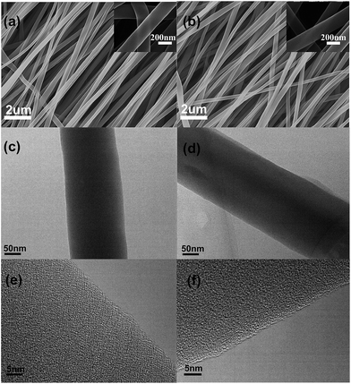
Fig. 1a presents the field emission scanning electron microscopy (FE-SEM) image of the 0B2O3–SnOx/CNFs, which exhibits a long continuous fibrous morphology with a diameter in the range of 200 nm to 300 nm. In Fig. 1b, the morphology of the 1.5B2O3–SnOx/CNFs is similar to that of 0B2O3–SnOx/CNFs. It was noted that the surface of both 0B2O3–SnOx/CNFs and 1.5B2O3–SnOx/CNFs nanofibers were smooth, and no nanoparticles were observed at the surface even under higher magnification, as shown in the inset images in Fig. 1a and b, suggesting that the B2O3–SnOx nanoparticles may be dispersed inside the CNFs. The transmission electron microscopy (TEM) images of 0B2O3–SnOx/CNFs and 1.5B2O3–SnOx/CNFs (Fig. 1c and d) show the uniform dispersion of B2O3–SnOx nanoparticles. Moreover, as observed in Fig. 1e and f, no distinct crystalline structures were observed, indicating that the B2O3–SnOx nanoparticles are amorphous and homogeneously dispersed as ultrafine nanoparticles. Such homogenous dispersion of B2O3–SnOx nanoparticles in CNFs is believed to be beneficial to the electrochemical performances of the B2O3–SnOx/CNFs electrodes.Thermogravimetric analysis (TGA) was carried out to determine the amounts of B2O3–SnOx nanoparticles inside the CNFs as shown in the Fig. 1S (seen in the ESI†). The weight loss in the first stage from room temperature to 200 °C is resulted from desorption of water vapor and evacuation of gaseous contents of the samples,34 and the sharp weight loss in the range of 200–550 °C is ascribed to the removal of carbon component. The four samples show similar compositions, which are composed of about 20 wt% of the B2O3–SnOx.
Fig. 2a shows the X-ray diffraction (XRD) patterns of the B2O3–SnOx/CNFs samples. All the curves exhibit a broad peak of amorphous graphitic carbon (JCPDS 13-0148) near 25°, while no other diffraction peaks can be observed, indicating the amorphous nature of the B2O3–SnOx particles. Moreover, no obvious difference can be seen from the Fig. 2a among the four B2O3–SnOx/CNFs samples, suggesting that boron addition has little influence on the crystal structure of SnOx/CNFs. Fig. 2b shows the Raman spectra of all B2O3–SnOx/CNFs samples. All the Raman spectra display two prominent peaks of the G band (1580 cm−1) and the D band (1350 cm−1) which are corresponding to the sp2-conjugated carbon structure and the disordered carbon structures.30,35 Generally, the intensity ratio of D band to G band (ID/IG) is used to estimate the disorder degree of carbon materials. The ID/IG values for all the B2O3–SnOx/CNFs samples were calculated to be ca. 1.2, with an indicator of low graphitization degree of the CNFs. However, it is worth noting that the ID/IG value falls from 1.19 for 0B2O3–SnOx/CNFs to 1.16 for 3B2O3–SnOx/CNFs, which shows the increase in the graphitization of CNFs with boron addition. This change of ID/IG value with boron addition is helpful for the efficient electron conduction when used as the anode materials for LIBs.36
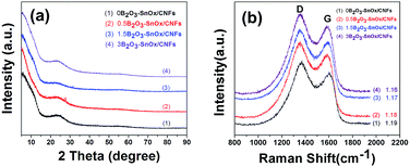 | ||
| Fig. 2 (a) XRD patterns and (b) Raman spectra of (1) 0B2O3–SnOx/CNFs, (2) 0.5B2O3–SnOx/CNFs, (3) 1.5B2O3–SnOx/CNFs, and (4) 3B2O3–SnOx/CNFs. | ||
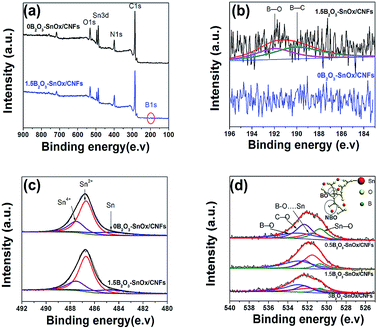
Fig. 3 shows the X-ray photoelectron spectroscopy (XPS) analysis of the 0B2O3–SnOx/CNFs and 1.5B2O3–SnOx/CNFs samples. As shown in Fig. 3a, the XPS general spectra present the signals of C, N, O and Sn elements for both 0B2O3–SnOx/CNFs and 1.5B2O3–SnOx/CNFs. In particular, B1s peak was detected at the binding energy around 190 eV on 1.5B–SnOx/CNFs. Fig. 3b displays the detailed B1s XPS spectra of the 1.5B2O3–SnOx/CNFs, which are evident for the existence of boron heteroatoms in the forms of B–C (binding energy of 190 eV) and B–O (binding energy of 192 eV) bonds.37 The B–C bonds in the 1.5B2O3–SnOx/CNFs indicates that boron enters the carbon lattice by substituting for carbon at the trigonal sites,38 which can acts as electron acceptor as it has three valence electrons, causing the improvement in electrical conductivity of the CNFs matrix.39 And the B–O bonds shows the boron maybe modify the structure of SnOx. The Sn3d5/2 spectrum in Fig. 3c was decomposed to three peaks at binding energy of 487.5, 486.7, and 484.7 eV, which are assigned to the Sn4+, Sn2+ and Sn0, respectively.40 Moreover, the proportions of Sn0, Sn2+ and Sn4+ for 1.5B2O3–SnOx/CNFs are similar to those for 0B2O3–SnOx/CNFs, demonstrating that boron addition has no significant effect on the valence state of Sn. Fig. 3d shows the XPS O1s spectra of 0.5B2O3–SnOx/CNFs, 1.5B2O3–SnOx/CNFs and 3B2O3–SnOx/CNFs. Four fitted peaks appeared in Fig. 4d: the two peaks at 530.7 and 532.3 eV are attributed to Sn–O and C–O, while the other two peaks at 532.9 and 531.5 eV are assigned to the bridging oxygen (BO: B–O–B) and the non-bridging oxygen (NBO: B–O⋯Sn).29,33 By calculating, the ratios of NBO to BO were 0.57, 1.07 and 0.73 for 0.5B2O3–SnOx/CNFs, 1.5B2O3–SnOx/CNFs and 3B2O3–SnOx/CNFs, respectively. It can be seen that the 1.5B2O3–SnOx/CNFs shows the highest NBO/BO ratio, which should be closely related to the electrochemical performance. Obviously, the chemical bonding in B–C, non-bridging oxygen in B–O⋯Sn, and the bridging oxygen in B–O–B reveal the chemical bonding interactions between B2O3 and SnOx/CNFs, forming the B2O3–SnOx glasses network in CNFs matrix by boron addition. The formed B2O3–SnOx glasses network is beneficial for compensating the large volume change of SnOx and prohibiting the aggregation of Sn particles by the bonding interactions of NBO during charged/recharged cycles.33
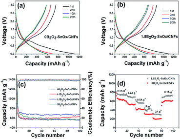
To investigate the electrochemical behavior of the B2O3–SnOx/CNFs electrodes, the 1st, 2nd, 10th, and 20th cycle charge/discharge voltage profiles of the 0B2O3–SnOx/CNFs and 1.5B2O3–SnOx/CNFs electrodes were measured at a current density of 200 mA g−1, as shown in Fig. 4a and b. The initial charge and discharge capacities for 0B2O3–SnOx/CNFs are 1106.4 and 753.7 mA h g−1. In comparison, the initial charge and discharge capacities for 1.5B2O3–SnOx/CNFs are 1126.2 and 852.2 mA h g−1, corresponding to a columbic efficiency of 75.7%, which is higher than that of 0B2O3–SnOx/CNFs (68.1%). Generally, the initial irreversible capacity is mainly attributed to the formation of solid electrolyte interphase (SEI) layer and the incompletely reversible reaction of SnOx to Sn and Li2O.41,42 Compared with 0B2O3–SnOx/CNFs, the 1.5B2O3–SnOx/CNFs electrode shows a higher initial columbic efficiency and specific capacity, suggesting that the reversibility of the reaction of SnOx to Sn and Li2O can be improved by boron addition. After the initial cycle, the columbic efficiency of 1.5B2O3–SnOx/CNFs electrode increases to about 100%, demonstrating the excellent cycling stability. Fig. 4c shows the cycling performance for all the samples in the potential range of 0.005–3 V at a current density of 200 mA g−1. After 100 cycles, the specific capacities for 0B2O3–SnOx/CNFs, 0.5B2O3–SnOx/CNFs, 1.5B2O3–SnOx/CNFs and 3B2O3–SnOx/CNFs are 565.7, 633.4, 670.2 and 580.4 mA h g−1, respectively. It is clear that the 1.5B2O3–SnOx/CNFs electrode exhibits the highest specific capacity of 670.2 mA h g−1 in the 100th cycle, which is about 20% higher than that of 0B2O3–SnOx/CNFs, and also better than those of other Sn-based composite anode materials such as Sn/SnOx/CNFs (510 mA h g−1@30 mA g−1, 40th),13 Sn/SnO2/MWCNT nanocomposites (374 mA h g−1@75 mA g−1, 100th),41 carbon coated Sn/graphene nanocomposites (566 mA h g−1@75 mA g−1, 100th),43 carbon-supported SnO2 nanowire arrays (403 mA h g−1@160 mA g−1, 60th),44 and graphene-wrapped SnO2 nanotubes (SnO2–NTs/G) (422.4 mA h g−1@100 mA g−1, 200th).45 Moreover, the rate capability of the 1.5B2O3–SnOx/CNFs has also been tested at various current densities from 100 to 2000 mA g−1 (Fig. 4d). As observed, the reversible capacities vary along with the discharging rates, and the values changes from 766.5 mA h g−1 (100 mA g−1) to 696.6 mA h g−1 (200 mA g−1), 557.3 mA h g−1 (500 mA g−1) 435.0 mA h g−1 (1000 mA g−1), and 300.2 mA h g−1 (2 A g−1), and then reversible back to 728.1 mA h g−1 (100 mA g−1), demonstrating the high rate capability of the 1.5B2O3–SnOx/CNFs.
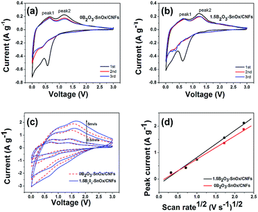
To disclose the mechanism for the enhanced electrochemical performances, the cyclic voltammetry (CV) measurement was performed on 0B2O3–SnOx/CNFs and 1.5B2O3–SnOx/CNFs at a scanning rate of 0.1 mV s−1 with the potential range of 0.005–3 V, as shown in Fig. 5a and b. The first cathodic peak observed at 0.6 V can be ascribed to the formation of SEI film and reduction of SnOx to Sn and Li2O, which should be responsible for the large irreversible capacity loss.46 Another peak appeared at around 0.01 V due to the insertion of Li+ into the CNFs. Two oxidation peaks appeared at around 0.55 V (peak 1) and 1.25 V (peak 2), as described by the following equations:31
| Sn + xLi+ + xe− ↔ LixSn, (0 ≤ x ≤ 4.4) | (1) |
| SnOx + 2xLi+ + 2xe− → Sn + xLi2O, (x ≤ 2) | (2) |
The 0.55 V (peak 1) is related to the alloying and dealloying LixSn (0 ≤ x ≤ 4.4) according to the eqn (1). An oxidation peak is also observed at about 1.25 V (peak 2) in the first cycle, which is mostly likely to be the formation of metallic Sn and Li2O as in eqn (2).34,46 Fig. 5c shows the CV curves of 0B2O3–SnOx/CNFs and 1.5B2O3–SnOx/CNFs electrodes at different scan rates (0.5, 1, 3, and 5 mV s−1). On the basis of these CV curves, the peak current (Ip, the peak near 1.25 V) is plotted as a function of the root of scan rate (v1/2) in Fig. 5d, which follows the Randles–Sevcik equation, Ip = (2.69 × 10⁵)n3/2D1/2C0v1/2, where n is the number of electrons per molecule during the intercalation, C0 is the concentration of lithium ions, D is the diffusion coefficient, and v is the scan rate.33 As can be seen from Fig. 5d, the liner correlations between Ip and v1/2 are obtained for both 0B2O3–SnOx/CNFs and 1.5B2O3–SnOx/CNFs, and the 1.5B2O3–SnOx/CNFs electrode shows a higher slope than 0B2O3–SnOx/CNFs, indicating that 1.5B2O3–SnOx/CNFs electrode has a larger Li+ transfer coefficient compared with 0B2O3–SnOx/CNFs. The significant enhancement of diffusion coefficient (D) in 1.5B2O3–SnOx/CNFs electrode could be attributed to the 3D network in the B2O3–SnOx glasses formed by boron addition, which facilitates ionic charge transfer in electrodes, and thus causing the enhanced rate capability.
The kinetic information for 0B2O3–SnOx/CNFs and 1.5B2O3–SnOx/CNFs electrodes is also provided by conducting the electrochemical impedance spectroscopy (EIS) measurements after 50 charge–discharge cycles, as shown in Fig. 2S (seen in the ESI†). An equivalent circuit used for fitting the impedance spectra is inserted in Fig. 2S.† Both the two curves consist of a semicircle and a straight line, standing for the overall resistance at interface (Rct) and diffusion of Li+ in the bulk electrode.33 The value of Rct for 0B2O3–SnOx/CNFs electrode (109.4 Ω) is larger than that of 1.5B2O3–SnOx/CNFs electrode (71.3 Ω), while the Li+ diffusion coefficient (straight line) of 0B2O3–SnOx/CNFs (1.513 × 10⁻³) is lower than that of 1.5B2O3–SnOx/CNFs (2.593 × 10⁻³). These results attest that boron addition into SnOx can enhance the ionic conductivity with decreasing charge transfer resistance, which is beneficial for improving the rate capability of SnOx/CNFs electrodes.
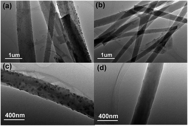
The morphologies of 0B2O3–SnOx/CNFs and 1.5B2O3–SnOx/CNFs electrodes after 100 cycles at a current density of 200 mA g−1 were investigated by HR-TEM. For the 0B2O3–SnOx/CNFs electrode (Fig. 6a and c), after 100 cycles many large particles with diameters in the range of 200 to 300 nm can be clearly found to locate randomly in the CNFs. However, in comparison, no obvious particles can be observed for the 1.5B2O3–SnOx/CNFs electrode (Fig. 6b and d) due to the formation of B2O3–SnOx glasses network in CNFs matrix, which can effectively buffer the large volume change of SnOx and prohibit the aggregation of Sn particles during charged/recharged cycles,47–49 causing the high cycle stability performance of the 1.5B2O3–SnOx/CNFs electrode.
Such good rate capability and reversibility of B2O3–SnOx/CNFs could be attributed to the following reasons:
(1) Boron is a unique element as substitution for carbon and Sn to promote the properties of electrical behaviour, leading to high reversibility.
(2) The B2O3–SnOx glasses network by the form of the bridging oxygen (BO: B–O–B) and the non-bridging oxygen (NBO: B–O⋯Sn) in CNFs matrix can provide a great number of active sites for the storage of lithium ions, leading to high capacity behaviours.
(3) The glasses network in the B2O3–SnOx can further effectively buffer the large volume change of SnOx and prohibit the aggregation of Sn particles during charged/recharged cycles.47,48
4. Conclusions
B2O3–SnOx/CNFs nanohybrids webs have been successfully prepared via electrospinning and subsequent thermal treatments. Boric acid in precursor solution is transformed to B2O3 during the carbonization process, forming the B2O3–SnOx glasses network by non-bridging oxygen (NBO) (B–O⋯Sn) in CNFs matrix. By controlling the addition of boric acid in the precursor solution, an optimal 1.5B2O3–SnOx/CNFs electrode (the approximate weight percent of boric acid to PAN is 1.5 wt%) has been obtained, which shows the highest reversible capacity of 670.2 mA h g−1 at 200 mA g−1 after 100 cycles, and a rate capacity of 300 mA h g−1 at the high current density of 2 A g−1. This excellent lithium-ion storage performance is associated with the 3D SnOx–B2O3 glasses network, which can not only accommodate the enormous volume change associated with lithium insertion/extraction and prevent the SnOx particles from agglomeration, but also provide enhanced diffusion for Li+ and charge transfer. The boron adding to SnOx/CNFs may be an effective route to develop the Sn-based anode materials with superior lithium-ion storage performance.Acknowledgements
This work was financially supported by National Natural Science Foundation of China (No. 51072013, 51272021, 51142004 and 51402010) and Natural Science Foundation of Jiangsu Province (No. BK20131147 and BK20140270).Notes and references
- J. B. Goodenough and Y. Kim, Chem. Mater., 2010, 22, 587 CrossRef CAS.
- W. Zhang, J. Power Sources, 2011, 196, 13 CrossRef CAS PubMed.
- B. Scrosati and J. Garche, J. Power Sources, 2010, 195, 2419 CrossRef CAS PubMed.
- V. Etacheri, R. Marom, R. Elazari, G. S. Salitra and D. Aurbach, Energy Environ. Sci., 2011, 4, 3243 CAS.
- Y. Wang, Z.-S. Feng, J.-J. Chen and C. Zhang, Mater. Lett., 2012, 71, 54 CrossRef CAS PubMed.
- Y. Wang, Z.-S. Feng, C. Zhang, L. Yu, J.-J. Chen, J. Hu and X.-Z. Liu, Nanoscale, 2013, 5, 3704 RSC.
- D. Saikia, T.-H. Wang, C.-J. Chou, J. Fang, L.-D. Tsai and H.-M. Kao, RSC Adv., 2015, 5, 42922 RSC.
- L. Zhan, S. Wang, L.-X. Ding, Z. Li and H. Wang, J. Mater. Chem. A, 2015, 3, 19711 CAS.
- J. Zhu, L. Chen, Z. Xu and B. Lu, Nano Energy, 2015, 12, 339 CrossRef CAS PubMed.
- Z. Sun, C. Cao and W.-Q. Han, RSC Adv., 2015, 5, 72825 RSC.
- D. Larcher, S. Beattie, M. Morcrette, K. Edstrom, J.-C. Jumas and J.-M. Tarascon, J. Mater. Chem., 2007, 17, 3759 RSC.
- Y. Zhang, Y. Liu and M. Liu, Chem. Mater., 2006, 18, 4643 CrossRef CAS.
- L. Zou, L. Gan, R. Lv, M. Wang, Z. Huang, F. Kang and W. Shen, Carbon, 2011, 49, 89 CrossRef CAS PubMed.
- H. Wang, P. Gao, S. Lu, H. Liu, G. Yang, J. Pinto and X. Jiang, Electrochim. Acta, 2011, 58, 44 CrossRef CAS PubMed.
- X. Zhou, L.-J. Wan and Y.-G. Guo, Adv. Mater., 2013, 25, 2152 CrossRef CAS PubMed.
- X. Niu, H. M. Zhou, Z. Y. Li, X. H. Shan and X. Xia, J. Alloys Compd., 2015, 620, 308 CrossRef CAS PubMed.
- X. Lou, J. Chen, P. Chen and L. A. Archer, Chem. Mater., 2009, 21, 2868 CrossRef CAS.
- I. Meschini, F. Nobili, M. Mancini, R. Marassi, R. Tossici, A. Savoini, M. L. Focarete and F. Croce, J. Power Sources, 2013, 226, 241 CrossRef CAS PubMed.
- B. Jang, S. Park and W. Lee, J. Alloys Compd., 2013, 574, 325 CrossRef CAS PubMed.
- Y. Wang, M. Wu, Z. Jiao and J. Y. Lee, Chem. Mater., 2009, 21, 3210 CrossRef CAS.
- S.-M. Paek, E. J. Yoo and I. Honma, Nano Lett., 2009, 9, 72 CrossRef CAS PubMed.
- P. Lian, J. Wang and D. Cai, J. Alloys Compd., 2014, 604, 188 CrossRef CAS PubMed.
- W. Zhang, J. Hu, Y.-G. Guo, S.-F. Zheng, L.-S. Zhong, W.-G. Song and L.-J. Wan, Adv. Mater., 2008, 20, 1160 CrossRef CAS PubMed.
- Y. Yu, Q. Yang, D. Teng, X. Yang and S. Ryu, Electrochem. Commun., 2010, 12, 1187 CrossRef CAS PubMed.
- L. Zou, L. Gan, F. Kang, M. Wang, W. Shen and Z. Huang, J. Power Sources, 2010, 195, 1216 CrossRef CAS PubMed.
- Y. Wang and T. Chen, Electrochim. Acta, 2009, 54, 3510 CrossRef CAS PubMed.
- C. Li, W. Wei, S. Fang, H. Wang, Y. Zhang, Y. Gui and R. Chen, J. Power Sources, 2010, 195, 2939 CrossRef CAS PubMed.
- D. Kim, D. Lee, J. Kim and J. Moon, ACS Appl. Mater. Interfaces, 2012, 4, 5408 CAS.
- Y. Liu, X. Yan, J. Lan, D. Teng, Y. Yu and X. Yang, Electrochim. Acta, 2014, 137, 9 CrossRef CAS PubMed.
- X. Liu, D. Teng, T. Li, Y. Yu, X. Shao and X. Yang, J. Power Sources, 2014, 272, 614 CrossRef CAS PubMed.
- R. Li, D. Li, D. Tian, G. Xia, C. Wang, N. Xiao, N. Li, N. H. Mack, Q. Li and G. Wu, J. Power Sources, 2014, 251, 279 CrossRef PubMed.
- G. Xia, N. Li, D. Li, R. Liu, N. Xiao and D. Tian, Mater. Lett., 2012, 79, 58 CrossRef CAS PubMed.
- A. Hayashi, M. Nakai, M. Tatsumisago, T. Minami, Y. Himei, Y. Miura and M. Katada, J. Non-Cryst. Solids, 2002, 306, 227 CrossRef CAS.
- J. Chen, Y. Tan, C. Li, Y. Cheah, D. Luan, S. Madhavi, F. Y. C. Boey, L. A. Archer and X. Lou, J. Am. Chem. Soc., 2010, 132, 6124 CrossRef CAS PubMed.
- R. Trócoli, S. Franger, M. Cruz, J. Morales and J. Santos-Pena, Electrochim. Acta, 2014, 135, 558 CrossRef PubMed.
- X. Bai, B. Wan, H. Wang and J. Jiang, J. Alloys Compd., 2015, 628, 407 CrossRef CAS PubMed.
- Z. Wu, W. Ren, L. Xu, F. Li and H. Cheng, ACS Nano, 2011, 5, 5463 CrossRef CAS PubMed.
- C. E. Lowell, J. Am. Ceram. Soc., 1967, 50, 142 CrossRef CAS PubMed.
- D.-W. Wang, F. Li, Z.-G. Chen, G. Q. Lu and H.-M. Cheng, Chem. Mater., 2008, 20, 7195 CrossRef CAS.
- B. Zhang, Y. Yu, Z. Huang, Y. He, D. Jang, W. Yoon, Y. Mai, F. Kang and J. Kim, Energy Environ. Sci., 2012, 5, 9895 CAS.
- M. Alaf, D. Gultekin and H. Akbulut, ACS Appl. Mater. Interfaces, 2013, 275, 244 CAS.
- X. Xia, X. Wang, H. Zhou, X. Niu, L. Xue, X. Zhang and Q. Wei, Electrochim. Acta, 2014, 121, 345 CrossRef CAS PubMed.
- D. Wang, X. Li, J. Yang, J. Wang, D. Geng, R. Li, M. Cai, T. K. Sham and X. Sun, Phys. Chem. Chem. Phys., 2013, 15, 3535 RSC.
- Z. Yang, S. Zhao, W. Jiang, X. Sun, Y. Meng, C. Sun and S. Ding, Electrochim. Acta, 2015, 158, 321 CrossRef CAS PubMed.
- P. Wu, X. Xu, Q. Zhu, X. Zhu, Y. Tang, Y. Zhou and T. Lu, J. Alloys Compd., 2015, 626, 234 CrossRef CAS PubMed.
- Y. Xu, Q. Liu, Y. Zhu, Y. Liu, A. Langrock, M. R. Zachariah and C. Wang, Nano Lett., 2013, 13, 470 CrossRef CAS PubMed.
- X. Wu, Z. Wang, L. Chen and X. Huang, Solid State Ionics, 2004, 170, 117 CrossRef CAS PubMed.
- H. Xiang, S. Fang and Y. Jiang, Solid State Ionics, 2002, 148, 35 CrossRef CAS.
- T. Yang and B. Lu, Phys. Chem. Chem. Phys., 2014, 16, 4115 RSC.
Footnotes |
| † Electronic supplementary information (ESI) available. See DOI: 10.1039/c5ra19387g |
| ‡ These authors contributed equally to this work. |
| This journal is © The Royal Society of Chemistry 2015 |

