Highly efficient and stable dye-sensitized solar cells based on SnO2 nanocrystals prepared by microwave-assisted synthesis†
Alexander
Birkel‡
a,
Yong-Gun
Lee‡
b,
Dominik
Koll‡
a,
Xavier Van
Meerbeek
a,
Stefan
Frank
a,
Mi Jin
Choi
c,
Yong Soo
Kang
*c,
Kookheon
Char
*b and
Wolfgang
Tremel
*a
aInstitut für Anorganische Chemie und Analytische Chemie, Johannes Gutenberg-Universität, Duesbergweg 10-14, D-55099, Mainz, Germany. E-mail: tremel@uni-mainz.de; Fax: +49-6131-39-25605; Tel: +49-6131-39-25135
bThe National Creative Research Initiative Center for Intelligent Hybrids, The WCU Program on Chemical Convergence for Energy and Environment, School of Chemical and Biological Engineering, Seoul National University, Seoul, 151-744, Korea. E-mail: khchar@snu.ac.kr; Fax: +82-2-873-1548; Tel: +82-2-880-7431
cWCU Department of Energy Engineering and Center for Next Generation Dye-Sensitized Solar Cells, Hanyang University, Seoul, 133-791, Korea. E-mail: kangys@hanyang.ac.kr; Fax: +82-2-2296-2969; Tel: +82-2-2220-2336
First published on 30th November 2011
Abstract
Highly efficient dye-sensitized solar cells (DSSCs) with excellent long-term stability were fabricated based on tin(IV) oxide (SnO2) nanocrystals with tunable morphologies and band energy levels. The nanocrystals were prepared by a facile, fast, and energy-saving microwave-assisted solvothermal reaction. Through variation of the precursor base used during nanocrystal synthesis control over morphology was achieved—precursor metal cations are known to have a strong influence on the growth process of SnO2 nanostructures. A simple and economic way to prepare semiconducting pastes for photoanodes was devised. The photovoltaic performance of dye-sensitized solar cells based on SnO2 photoanodes was investigated. A very high power conversion efficiency of up to 3.2%, based on very high Voc and comparable Jsc and FF [under 1 Sun condition (AM 1.5, 100 mW cm−2, with shading masks)] was achieved, reporting the highest efficiency value for the cells based on unmodified SnO2 nanocrystals so far. In order to elucidate the efficient cell behavior, electrochemical properties such as the charge transport in the photoanodes as well as SnO2/electrolyte interfacial properties were investigated. Uncharacteristically for DSSCs, all devices tested in the present study show an unusual long-term stability under ambient conditions over several weeks.
Broader contextAmong the variety of solar cell devices, dye-sensitized solar cells (DSSCs) certainly belong to the most successful types throughout the world. This is mostly because of their cheap and easy production and the broad range of colorful dyes that are available, making them suitable, for example, for building integrated photovoltaic systems.Consisting of basically four main parts (photoanode, dye, electrolyte and counter electrode [cathode]), each of them has attracted much interest, leading to a more profound understanding of the processes that are involved in the conversion of light to electrical energy. Yet, many processes in dye-sensitized solar cells are still far from being understood. The work presented here focuses on the outstanding long-term stability of SnO2-based DSSCs. The SnO2 nanocrystals are made using a microwave-assisted solvothermal synthesis. This allows the preparation of large amounts of material, which can be upscaled easily. As the total amount of energy that is needed to fabricate solar-cells must be taken into account for calculating the “break-even” point, any reduction in the energy costs is greatly appreciated. |
Introduction
The high surface area of nanomaterials indicates that their interfaces play an important role in determining their physical properties and the photovoltaic performance of dye-sensitized solar cells1–3 (DSSCs). To optimize their performance, efficient charge transport in the semiconductor nanocrystals (i.e., low recombination rate and low scattering at the interfaces) is required.4,5In the most efficient DSSCs, TiO2 nanoparticles have widely been used as photoanodes and substrates for dye molecules due to their high device performance, based on their large surface area and their relevant band-gap position.2,6–8 However, other oxides9 such as ZnO,10,11Nb2O512,13 and SnO210,14–17 have also been used. Tin(IV) oxide (SnO2) is a stable, n-type, and wide band-gap semiconductor18 (Eg = 3.6 eV at 300 K) with excellent optical and electrical properties,19 such as fast electron conductivity20–22 (which is orders of magnitudes higher than TiO2) and high stability even under long-term UV-radiation.23 Nanostructured SnO2 materials have been investigated extensively for application as photoelectrodes in DSSCs.24 However, SnO2 based DSSCs were realized with less success than TiO2 or ZnO; the power conversion efficiency of cells employing SnO2 photoanodes is inferior to those based on TiO2 photoanodes.15 The poor device performance has been attributed mostly to the faster electron recombination in the SnO2 layers as well as the weaker adsorption of dyes with acidic carboxyl groups.4,25 Additionally, in the case of SnO2 photoanodes, low open-circuit voltage (Voc) values were frequently observed, most likely due to the intrinsically lower value of the conduction band energy level compared to TiO2.7,26–28 As the open circuit voltage is a crucial factor for the performance of dye-sensitized solar cells, several attempts have been made to improve the low Voc of SnO2 photoanodes.14,15
In principle, SnO2 electrodes could achieve a similar or even better device performance if the interfacial problems mentioned above could be overcome. Possible strategies to optimize such interfacial properties of SnO2 photoanodes are surface modification (e.g. core–shell nanoparticles with shells consisting of TiO2, ZnO, Al2O3 or MgO) and morphological control of the nanocrystals.15,16,23,25,29 In this contribution, SnO2 nanocrystals with different morphologies were prepared by a fast, facile, and energy-efficient microwave-assisted synthetic technique that allowed us to prepare large quantities of nanocrystals in a short reaction time. These various tin dioxide nanocrystals were employed for the fabrication of DSSCs to explore the impact of the nanocrystal morphology on their device performance. Furthermore, a very convenient and easy way to prepare the required semiconducting paste (for the preparation of the photoanodes) is presented. The electrochemical properties, such as the charge transport in SnO2 based photoanodes, and SnO2/electrolyte interfacial properties were investigated in detail using current–voltage characteristics measurements, IPCE (incident photon-to-current conversion efficiency), and EIS (electrochemical impedance spectroscopy) studies.
Experimental section
Materials
All materials were used without further purification or treatment. SnCl4·5H2O (98%) was purchased from Sigma Aldrich. The precursor base solutions were prepared by mixing appropriate amounts of NaOH (≥99%), KOH (≥90%), tetramethylammonium hydroxide (TMAH, 25% w/w in water) and NH4OH (25%), all from Sigma Aldrich, with Milli-Q water. Ethanol (p.a.) was purchased from Carl Roth and VWR. PEG 400 and PEG 20![[thin space (1/6-em)]](https://www.rsc.org/images/entities/char_2009.gif) 000 were obtained from Sigma Aldrich. Triton-X-100 was obtained from Acros Organics.
000 were obtained from Sigma Aldrich. Triton-X-100 was obtained from Acros Organics.
Chemicals used for the fabrication of solar cells included MPII (1-methyl-3-propylimidazolium iodide, Sigma Aldrich), LiI (lithium iodide, Sigma Aldrich), I2 (iodine, Sigma Aldrich), N719 (cis-diisothiocyanato-bis(2,2′-bipyridyl-4,4′-dicarboxylato)-ruthenium(II) bis(tetrabutylammonium), Solaronix), tBP (4-tert-butylpyridine, Aldrich), and GuSCN (guanidinium thiocyanate, Sigma). Acetonitrile and tert-butanol were obtained from Sigma-Aldrich.
Synthesis of SnO2 nanocrystals
SnO2 nanocrystals were prepared using a microwave-assisted method.30,31 In a typical procedure, 3.5 mL of 0.5 M tin(IV) chloride solution in water and 3.5 mL of 5 M NaOH (or KOH, TMAH,§NH4OH) were mixed with 12.5 mL of a 1![[thin space (1/6-em)]](https://www.rsc.org/images/entities/char_2009.gif) :
:![[thin space (1/6-em)]](https://www.rsc.org/images/entities/char_2009.gif) 1 volumetric mixture of ethanol/water. After several minutes of stirring, the reaction mixture was transferred into a 100 mL Teflon liner and finally sealed in a CEM XP-1500 microwave vessel. After a heating ramp of 10 min, the reaction mixture was allowed to react in the microwave for 2 h at an internal pressure of 46 bar, corresponding to the temperature of 240 °C. After radiative cooling, the obtained white-gray powders were separated by centrifugation (9000 rpm) and washed several times with water and ethanol. Finally, the powder was dried at 75 °C overnight.
1 volumetric mixture of ethanol/water. After several minutes of stirring, the reaction mixture was transferred into a 100 mL Teflon liner and finally sealed in a CEM XP-1500 microwave vessel. After a heating ramp of 10 min, the reaction mixture was allowed to react in the microwave for 2 h at an internal pressure of 46 bar, corresponding to the temperature of 240 °C. After radiative cooling, the obtained white-gray powders were separated by centrifugation (9000 rpm) and washed several times with water and ethanol. Finally, the powder was dried at 75 °C overnight.
Materials characterization
| CShkl = 1/norm (hT × Cij × h) |
Fabrication of DSSCs
![[thin space (1/6-em)]](https://www.rsc.org/images/entities/char_2009.gif) 000 dissolved in water (5.5 g in 5 mL) was added and the mixture was homogenized in a ball-mill for 45 minutes.
000 dissolved in water (5.5 g in 5 mL) was added and the mixture was homogenized in a ball-mill for 45 minutes.
![[thin space (1/6-em)]](https://www.rsc.org/images/entities/char_2009.gif) 000 and ethanol) applied on a FTO substrate (sheet resistance 8 Ω sq−1, Pilkington). The anode was then sintered at 450 °C for 30 min (Scheme 1).
000 and ethanol) applied on a FTO substrate (sheet resistance 8 Ω sq−1, Pilkington). The anode was then sintered at 450 °C for 30 min (Scheme 1).
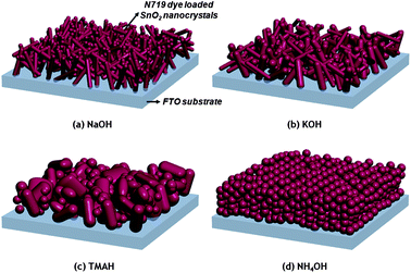 | ||
| Scheme 1 Schematic illustration of various types of SnO2 nanostructures based on different precursors on the FTO substrate. | ||
The SnO2 electrodes prepared as described above were dipped into a 0.3 mM solution of N719 dye in acetonitrile and tert-butanol (1![[thin space (1/6-em)]](https://www.rsc.org/images/entities/char_2009.gif) :
:![[thin space (1/6-em)]](https://www.rsc.org/images/entities/char_2009.gif) 1 v/v) for 18 h at 30 °C and then rinsed with acetonitrile and dried with a nitrogen gas flow. The electrolyte consists of 0.1 M LiI, 0.6 M 1-methyl-3-propylimidazolium iodide (MPII), 0.05 I2, 0.5 M 4-tert-butylpyridine (tBP), and 0.05 M guanidinium thiocyanate (GuSCN) in acetonitrile. A Pt counter electrode was prepared by thermal decomposition of 0.01 M H2PtCl6 in isopropyl alcohol solution spun cast on a FTO substrate, followed by sintering at 450 °C for 30 min.
1 v/v) for 18 h at 30 °C and then rinsed with acetonitrile and dried with a nitrogen gas flow. The electrolyte consists of 0.1 M LiI, 0.6 M 1-methyl-3-propylimidazolium iodide (MPII), 0.05 I2, 0.5 M 4-tert-butylpyridine (tBP), and 0.05 M guanidinium thiocyanate (GuSCN) in acetonitrile. A Pt counter electrode was prepared by thermal decomposition of 0.01 M H2PtCl6 in isopropyl alcohol solution spun cast on a FTO substrate, followed by sintering at 450 °C for 30 min.
Two holes on the Pt counter electrode for electrolyte injection were subsequently made using a drill. Afterwards, a Surlyn (25 μm, Solaronix) film, used as a spacer, was sandwiched between a SnO2 photoanode and a Pt counter electrode at 90 °C. For the last step of DSSC fabrication, the electrolyte was filled into the gap of the spacer through one of the two small holes in the Pt counter electrode, which was then subsequently sealed by a Surlyn film and a cover glass. TiO2 cells were fabricated to compare the performance of the SnO2 devices to a known system. A TiO2 paste (18NR, mostly anatase, some rutile, ∼17% TiO2 content) with particles approx. 20 nm in size (spherical particles and short rods) was supplied by CCIC. The fabrication of the cells was performed as described above for the SnO2 devices.
Solar cell characterization
The photovoltaic performance of DSSCs based on SnO2 photoanodes was characterized by current–voltage (J–V) measurements and incident photon-to-current conversion efficiency (IPCE). The current–voltage characterization of DSSCs was carried out using a Keithley Model 2400 source meter and a solar simulator with a 300 W xenon arc-lamp (Newport) under 1 Sun illumination (AM 1.5, 100 mW cm−2). The light intensity was calibrated by a silicon solar cell (PV Measurements, Inc.). A light shading mask was applied on the residual area of the front side of a FTO substrate except for an active area of 0.25 cm2, thus preventing the overestimation of power conversion efficiency. In addition, the quantum efficiency of DSSCs was analyzed by an IPCE device (PV Measurements, Inc.) The analysis of the work functions of SnO2 photoanodes prepared with different precursor cations was evaluated by photoelectron spectroscopy using an AC-2 photoelectron spectrometer (RKI Instruments, Inc., Japan) under ambient conditions. The interfacial properties were characterized by electrochemical impedance spectroscopy (EIS) using an IM6 (Zahner) under dark conditions. A bias potential of open-circuit voltage (Voc) was applied between the two electrodes and the frequency range was varied from 1 MHz to 100 mHz with a fixed amplitude of 10 mV.Charge extraction, IMPS, and IMVS
The photo-induced charge density as a function of white light bias intensity was obtained by charge extraction measurements where the stored charges under open circuit conditions were extracted by placing the cell under short circuit conditions.35,36The electron diffusion coefficient and electron lifetime were obtained by IMPS (intensity-modulated photocurrent spectroscopy) under short-circuit conditions and IMVS (intensity-modulated photovoltage spectroscopy) under open-circuit conditions as a function of light intensity using a CIMPS (Controlled Intensity Modulated Photo Spectroscopy) system (Zahner). The detailed explanation for measurements is described elsewhere.37,38
Results and discussion
Materials characterization
The crystallographic phases of all SnO2 nanocrystals were determined by X-ray powder diffraction. Fig. 1 shows that all samples yielded phase pure SnO2 nanocrystals (cassiterite, PDF-2, entry (41-1445), tetragonal space group: P42/mnm) regardless of the precursor cation. Full profile pattern fittings were applied to confirm the structural parameters of the samples as well as to determine the crystallite sizes and to obtain a first indication of the anisotropy. The refined crystallite size values are summarized in Table S1†. The reflection profiles of the SnO2 nanocrystals prepared with NH4OH were all very broad, indicating a small crystallite size of the nanocrystals. A value of 9 ± 0.15 nm was determined by full profile pattern fitting. No preferred growth orientation was found as all three crystallite sizes (obtained from the Rietveld refinement) were approximately identical. A comparison with the values obtained for the three other nanocrystalline SnO2 products (prepared with NaOH, KOH and TMAH¶) showed all of them to exhibit at least some anisotropy in the [001] (i.e., the c) direction (also see Table S1†). In addition, all reflection profiles are much narrower, indicating larger crystallite sizes, as shown in Fig. 1 and Table S1†.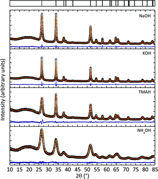 | ||
| Fig. 1 X-Ray powder diffraction data of samples prepared with different precursor bases including full pattern profile fits of the data. All samples show phase pure SnO2. The varying background intensity was observed due to slight variations in the sample preparation and the alterations of the total scattering intensity at low scattering angles. | ||
Fig. 2 shows the TEM micrographs of various SnO2 nanocrystals obtained with different precursor bases. With NaOH, homogeneous bundles of nanorods (around 150 nm in length and 5–10 nm in diameter, as shown in Fig. 2(a)) were obtained. SnO2 nanocrystals obtained with KOH were less anisotropic: in addition to polydisperse rods (from 10 nm up to 200–300 nm in length and 100 nm in diameter), the sample contained spherical particles (with diameters ranging from 5 to 10 nm) and larger “plate-like” structures as shown in Fig. 2(b). TMAH led to the formation of a mixture of spherical-, plate- and rod-like particles.
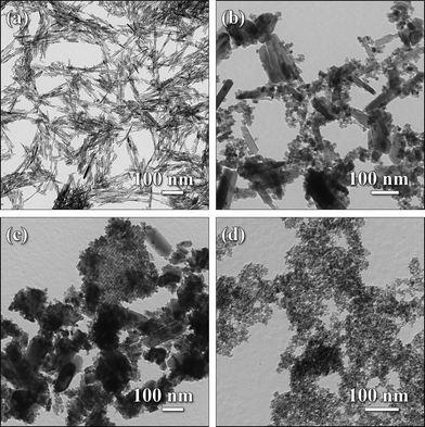 | ||
| Fig. 2 TEM micrographs of as-prepared SnO2 particles with various morphologies obtained from microwave-assisted reactions. The images show the nanorod crystals obtained with NaOH (a) and the crystal morphologies prepared with KOH (b). The bottom row shows samples obtained with TMAH (c) and spherical nanocrystals prepared with NH4OH (d). | ||
An interesting feature of these SnO2 nanocrystals was the formation of larger “platelets” consisting of inter-connected smaller particles, as shown in Fig. 2(c). Additionally, we note that in a typical sample of SnO2 nanoparticles prepared with TMAH precursor base, the amount of smaller particles and the amount of larger ill-defined particles are larger than the amount in samples of SnO2 nanocrystals prepared with KOH. As observed in earlier studies,30 the use of NH4OH as a precursor base in the synthesis of SnO2 nanocrystals leads to the formation of small and spherical particles (∼8 nm in diameter and nearly monodisperse in size, as shown in Fig. 2(d)). These morphological data, obtained from TEM, are in good agreement with the values deduced from the XRD data. The morphological trends for the nanocrystals obtained from microwave reactions are comparable with those for solvothermal reactions in a conventional steel autoclave.30 However, reaction times could be greatly reduced.
Device characterization
SnO2 nanocrystals with different morphologies were tested for their performance as photoanodes in dye-sensitized solar cells. SEM images of the sintered anodes were obtained to assure a high degree of reproducibility. Fig. 3 shows both top-view and cross-sectional scanning electron micrographs of sintered photoanodes.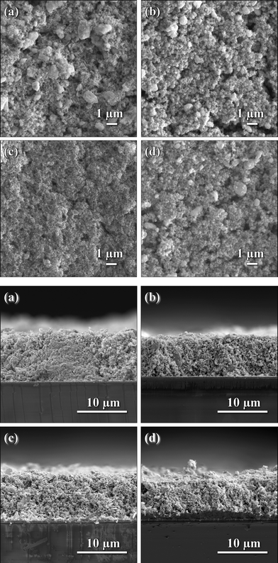 | ||
| Fig. 3 Top-view (top) and cross-sectional (bottom) SEM pictures of as prepared SnO2 photoanodes with various morphologies: (a) NaOH; (b) KOH; (c) TMAH; and (d) NH4OH. | ||
All prepared photoanode films had reasonably smooth surfaces with few cracks or voids. A ball milling step was employed in order to reduce the amount of large agglomerates. Only the film prepared with rod-shaped particles showed several larger residual agglomerates, around 2–3 μm in size, due to the possibility of SnO2 nanorods growing in an interconnected fashion (see the TEM image in Fig. 2(a)). These agglomerates are too small to be completely homogenized by the ball-mill. It is important to emphasize that the ball-milling step did not change the morphology of the obtained nanocrystals (the resulting fineness is 10 μm way above the size of the nanocrystals). It was only employed to achieve a more homogeneous distribution of the powders in the semiconducting paste, i.e., a more effective grinding.
All cross-sectional SEM images (Fig. 3) show that the films uniformly contact the FTO substrates without noticeable large irregularities. All SnO2 photoanodes used in the present study featured comparable film-thicknesses in the range of 8–11 μm.
In order to gain insight into the factors that determine the photovoltaic performance of different SnO2 photoanodes, the surface area of SnO2 photoanodes with different nanocrystal morphologies as well as the amount of dye loading of the photoanodes were determined and are summarized in Table 1. The surface area derived from multipoint BET measurements agrees well with the trend that could be expected from the TEM images: with decreasing size of the SnO2 nanocrystals, the surface area of the SnO2 photoanodes increases because of the increasing surface-to-volume ratio.
| Sample | BET surface (m2 g−1) | Dye loading (mol cm−2) | Thickness (μm) | Work function (eV) | V oc (V) | J sc (mA cm−2) | FF | Eff. (%) |
|---|---|---|---|---|---|---|---|---|
a
Sensitizer: 0.3 mM N719 dye in acetonitrile and tert-butanol (1![[thin space (1/6-em)]](https://www.rsc.org/images/entities/char_2009.gif) : :![[thin space (1/6-em)]](https://www.rsc.org/images/entities/char_2009.gif) 1, v/v); electrolyte: 0.1 M LiI, 0.6 M MPII, 0.05 M I2, 0.5 M tBP, and 0.05 M GuSCN dissolved in acetonitrile; measured under 1 Sun condition (AM 1.5, 100 mW cm−2) with shading masks, active area: 0.25 cm2. 1, v/v); electrolyte: 0.1 M LiI, 0.6 M MPII, 0.05 M I2, 0.5 M tBP, and 0.05 M GuSCN dissolved in acetonitrile; measured under 1 Sun condition (AM 1.5, 100 mW cm−2) with shading masks, active area: 0.25 cm2.
|
||||||||
| NaOH | 51 | 8.2 × 10⁻⁸ | 8–10 | 5.35 | 0.575 | 8.90 | 0.614 | 3.14 |
| KOH | 66 | 9.0 × 10⁻⁸ | 9–11 | 5.42 | 0.526 | 9.43 | 0.559 | 2.77 |
| TMAH | 69 | 1.0 × 10⁻⁷ | 10–12 | 5.47 | 0.503 | 9.87 | 0.637 | 3.16 |
| NH4OH | 149 | 1.1 × 10⁻⁷ | 9–11 | 5.51 | 0.405 | 9.47 | 0.416 | 1.60 |
| TiO2 | 50 | 5.4 × 10⁻⁸ | 9–10 | 5.32 | 0.735 | 12.06 | 0.746 | 6.62 |
According to the BET measurements, the SnO2 photoanodes prepared with NH4OH (small spheres) possess a large surface area (149 m2 g−1) that is almost three times larger than the surface area of the SnO2 nanorod films prepared with NaOH (51 m2 g−1) as precursor base. The surface areas of “KOH” and “TMAH” samples (both consisting of the mixtures of spheres, plate-like structures and rods) have intermediate values (66 and 69 m2 g−1, respectively), as expected from the TEM morphologies shown in Fig. 2.
Interestingly, the average amounts of dye for the different SnO2 photoanodes are almost identical: only a slightly larger amount of dye was found to adsorb onto the SnO2 photoanode with the highest surface area. As all cells contained almost identical amounts of adsorbed dye molecules, the measured trend in photocurrent-density should be caused by other factors like surface modifications, e.g. adsorbed ions originating from different precursor bases or various exposed crystal faces with different adsorption behavior. The exact elucidation of the factors contributing to the device performance is the subject of ongoing research.
Photovoltaic performance of SnO2-based DSSCs
Fig. 4 and Table 1 show the current–voltage characteristics of DSSCs based on SnO2 photoanodes. All devices show high power conversion efficiencies, all well above 1.5%, probably due to the quality of the photoanode films and devices16,39 investigated in this study. Devices prepared with spherical nanoparticles (“NH4OH”) exhibited an efficiency of 1.6% and a Voc of 0.405 V. In comparison, remarkably high Voc (and Jsc) values along with the overall efficiency of 3.15% (measured under 1 Sun illumination condition [AM 1.5, 100 mW cm−2] with shading masks) were obtained with the cells based on bundles of SnO2 nanorods (“NaOH” sample) or a mixture of different nanostructures (“TMAH” sample) as photoanodes. To the best of our knowledge, these values are the highest values reported so far for SnO2 based DSSCs employing I3−/I− electrolytes as well as N719 Ru-based dyes used as the sensitizer.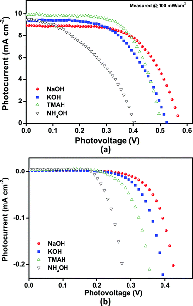 | ||
| Fig. 4 Current–voltage characteristics of SnO2 nanoparticle based DSSCs, obtained from various precursor bases. (a) Under 1 Sun illumination (AM 1.5, 100 mW cm−2) and (b) dark conditions with shading masks. The active area is 0.25 cm2 in both cases. | ||
The fill factor is above 40% in all tested cells, the highest values were obtained with the “TMAH” and “NaOH” devices (64% and 61%, respectively). It is evident that the increase in efficiency (compared to other cells based on SnO2 nanoparticles) can be attributed to some extent to the high fill factor observed in these cells.
The “NH4OH” (41%) cell exhibited the lowest value, while the “KOH” cell showed an intermediate value. The low fill factor for the “NH4OH” cell might result from higher internal/interfacial resistances, resulting from a poor interconnectivity between spherical nanocrystals, as shown in Fig. 2(d), and/or a high electron recombination rate with I3− ions in the electrolyte or with oxidized dye molecules, which may be due to a partially (dye)-uncovered surface caused by low dye adsorption. This deleterious effect is more effectively suppressed in the other SnO2 samples. Additionally the film quality of the “NH4OH” samples is comparably low.
The most striking feature in the characterization of DSSCs based on SnO2 photoanodes in this study is the very high Voc for the electrode employing SnO2 nanorods (“NaOH” cell). The position of the conduction band of SnO2 has been determined to be approximately 0–0.1 V (vs.normal hydrogen electrode, NHE), implying that it is almost 0.4–0.5 V lower than that of TiO2.26–28
The redox-potential of the I3−/I− couple lies in the range between 0.3 and 0.53 V (vs.NHE),40–42 depending on the solvent and the electrolyte concentration. This limits the Voc to approximately 600 mV, which is comparable to the Voc value obtained in this study. This behavior can be explained by the change in the flat-band potential for anisotropic and rod-like SnO2 nanocrystals (see below).39 The high Voc is also evident in the dark current. The onset dark current increases from the “NH4OH” to the “NaOH” samples, as shown in Fig. 4(b), which is consistent with the observed Voc behavior. Voc decreases from the “NaOH” to the “KOH”, “TMAH” and finally to the “NH4OH” cells, which is in the same order as the decreasing amount of rod-like nanocrystals (in other words, the increasing number of spherical nanocrystals).
Thus, Voc seems to depend strongly on the morphology of the SnO2 nanocrystals employed for the photoanode (and possibly also on the adsorbed cationic species on the surface—see dye adsorption): the more anisotropic the nanoparticles in the photoanode, the higher the open-circuit voltage.
All DSSC samples showed high current density values of 9 mA cm−2. Only for “NaOH”-based SnO2 photoanodes a slightly lower Jsc was obtained, which could be attributed to a slightly lower film thickness and/or the lower driving force for charge injection from the dyes because their relative band energy level is highest compared to other types of SnO2 photoanodes presented here. The Jsc results are consistent with the IPCE (incident photon-to-current conversion efficiency) spectra of the cells, as shown in Fig. 5. All devices showed high quantum efficiencies at around 510–520 nm corresponding to the absorption maximum of the dyes. In particular, the maximum IPCE reached up to 68% for the “TMAH” sample. The efficiency of the cells gradually increased over 10–15 days and subsequently remained nearly unchanged up to 50 days under ambient conditions (see Fig. 6).
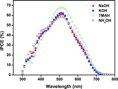 | ||
| Fig. 5 Incident photon-to-current conversion efficiency (IPCE) of DSSCs based on SnO2 photoanodes with different morphologies. | ||
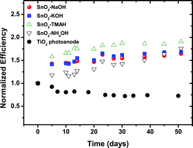 | ||
| Fig. 6 Normalized efficiency for DSSCs with SnO2 photoanodes derived from different precursors under 1 Sun condition during 50 days stored under ambient conditions. The change in performance over time was compared to a cell prepared with TiO2 nanoparticles. | ||
The increase in efficiency with time is due to the enhancement of both Voc and FF, while Jsc remains constant. All values reported in the present study are obtained from the saturated cell efficiencies after 15 days (i.e., the efficiency was measured after no further significant increase in the cell performance was observed). The increase in efficiency over an extended period of time (10–15 days) is an unusual behavior for DSSCs, particularly when a liquid, acetonitrile-based electrolyte is used.
Typically, this kind of device shows the degradation in device performance during a long-term stability test.43,44 Although no standard long-term stability test was employed, this increase in efficiency is a highly unusual behavior. In addition, it should be emphasized that the increasing efficiency with time was observed for all the cells regardless of film thickness or the amount of dye-loading. The exact reason for the observed time-dependent behavior (i.e., the increase in efficiency during several weeks) is still under examination.
Characterization of the band-edge movement
The variation of Voc could be traced independently by measuring the accumulated charge of SnO2 DSSCs under open-circuit conditions and also by using the work function measurements on SnO2 photoanodes (after the dye-loading step) with a photoelectron spectrometer (AC-2) under ambient conditions. The results are plotted in Fig. 7(a) and (b).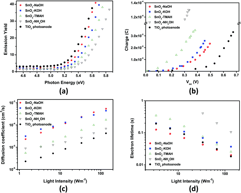 | ||
| Fig. 7 (a) Work function of SnO2 photoanodes under ambient conditions and (b) accumulated charge of DSSCs based on SnO2 photoanodes measured under short-circuit conditions. (c) Electron diffusion coefficient and (d) lifetime of DSSCs based on SnO2 photoanodes measured by IMPS (intensity-modulated photocurrent spectroscopy) and IMVS (intensity-modulated photovoltage spectroscopy) as a function of light intensity. In all cases, a TiO2 reference cell was measured to compare our results to a known, standardized system. | ||
The increase in Voc may be influenced by the intensity of the negative band edge movement of the SnO2 layer depending on the precursor base cations. As shown in Fig. 7(b), Voc increased from sphere-type (“NH4OH”) to rod-type (“NaOH”) SnO2 electrodes at the same capacitance, indicating the negative band-edge shift.
It has been anticipated that such negative band edge movement may be due to the different morphology (or anisotropy) of the SnO2 nanocrystals depending on the precursor base employed. Gubbala et al. reported that nanowires with single crystal surfaces (1–2 types of facets) showed a negative shift in their flatband potentials (we use the term ‘flatband potential’ to match the terminology used in this reference, in fact, it describes a shift of the conduction band edge) compared to nanospheres based on a high degree of surface polycrystallinity (i.e., mixed facets and a large number of edge sites).39,45,46 In addition, a flat-band potential shift with crystallographic orientation or surface crystallinity has been reported. The rod-like particles showed regular edges and tips, indicative of well-defined lateral limits, closely related to the single crystal structure. Their surface was highly crystalline, and only a few thermodynamically stable crystal orientations were observed (e.g. {110} as the lateral limit).30 When the amount of “ill-defined” nanocrystals was increased, the surface polycrystallinity may be expected to increase as well, resulting in a variety of edge sites and surface facets (e.g.NH4OH particles that had been investigated by HR-TEM in an earlier study30 were all highly crystalline and terminated mostly by the (110) face, but other orientations, such as (011), were found more often), which eventually causes a more positive shift of the band potential. The band-edge shift is consistent with the change in Voc observed in this study, suggesting that the band-edge shift may be a dominant factor in determining Voc.
As shown in Fig. 7(a), the work function was measured as a function of the morphology of the SnO2 nanocrystals as well to support the idea of a band-edge shift behavior as described above. The work function gradually increased by 0.16 eV for the “NH4OH” cell compared to 5.35 eV for the rod-type SnO2 photoanodes (“NaOH” cells). The large work function leads to the decrease in the energy difference with respect to the redox-potential of the I3−/I−redox-couple electrolyte which in turn leads to the decrease in Voc. The change in the work function is also consistent with the band-edge shift. This indicates that the band-edge shift has a dominant influence on the change in Voc. The same result was obtained from the measurements of the accumulated charge of the SnO2 DSSCs under open circuit conditions.
Electron transport and lifetime in SnO2 nanocrystals
In order to determine the electron diffusion coefficient and lifetime for SnO2 photoanodes of different types, IMPS and IMVS were performed as a function of light intensity. As shown in Fig. 7(c), as the portion of the rod-type SnO2 nanocrystals increased the electron diffusion coefficient became larger. Moreover, we note that the electron diffusion coefficient through nanorod-rich SnO2 electrodes obtained with “NaOH” and “KOH” precursor bases was ∼5 × 10⁻⁴ cm2 s−1 at 100 W m−2, which is almost 10 times faster than the value obtained from TiO2 nanoparticles.The electron lifetime of SnO2 based DSSCs also depends on the precursor base, but not in such a pronounced way as the electron diffusion coefficient. The electron lifetime for the “NH4OH” SnO2 photoanode was almost one order of magnitude longer than the value for TiO2 photoanode (see Fig. 7(d)). This result is unexpected because photoanodes based on sphere-type SnO2 (“NH4OH” sample) exhibited the lowest Voc and FF.
As shown in Fig. S2†, the results of the electrochemical impedance spectroscopy under 1 Sun illumination with a bias open-circuit voltage show a behavior that is consistent with that from intensity-modulated photovoltage spectroscopy. These results indicate that SnO2 based DSSCs exhibit a higher electron recombination resistance compared to TiO2 based DSSCs. Furthermore, they show a different behavior as a function of the morphologies of the SnO2 nanocrystals.
Conclusions
Highly efficient dye-sensitized solar cells employing SnO2 nanocrystals as photoanodes were fabricated. SnO2 nanocrystals with different morphologies were prepared with different precursor bases using the fast, facile, and energy-efficient microwave-assisted reaction pathway. The SnO2 nanocrystals were investigated using X-ray powder diffraction and transmission electron microscopy, showing that the powder morphology is strongly dependent on the type of cations used for the synthesis of SnO2 nanocrystals.When DSSCs based on SnO2 photoanodes with different powder morphologies were tested for the current–voltage characteristics, all cells in the present study yielded fairly high power conversion efficiencies above 1.6%, likely due to the high quality of the SnO2 films on FTO substrates. We note that the device efficiency is sensitive to the type of employed SnO2 nanocrystals: the highest power conversion efficiencies were 3.14% and 3.16% with fill factors above 61% and 64%, respectively. These are the highest values ever reported for SnO2 based DSSCs. They were achieved with SnO2 nanorods prepared with NaOH precursor base or with a mixture of different morphologies prepared with TMAH precursor base, respectively.
V oc was observed to depend strongly on the precursor base used for the synthesis of the SnO2 nanoparticles. We believe that the high efficiency of the DSSCs based on SnO2 photoanodes can be explained by the low rate of recombination losses at the interfaces and the shift of the flat-band potential due to the anisotropic nanocrystal morphology and efficient electron diffusion through the network of interconnected nanorods. This was substantiated by spectroscopic and electrochemical measurements.
Finally, all DSSCs based on SnO2 nanocrystals showed unusual long-term power conversion stability (under ambient conditions) unlike other DSSCs based on TiO2 photoanodes that show fast degradation of efficiency when standard N719 dyes and I3−/I−redox couple electrolytes were used.
Acknowledgements
The work presented here was supported and financed by the International Research Training Group (IRTG) Optoelectronics Mainz-Korea and the Graduate School of Excellence, MAINZ, funded by the Deutsche Forschungsgemeinschaft (DFG). We thank Dr. Martin Panthöfer for helpful discussions concerning the XRD data. Additionally, this work was supported by the Basic Science Research Program for the Center for Next Generation Dye-Sensitized Solar Cells (no. 2010-0001842) and the National Creative Research Initiative Center for Intelligent Hybrids (no. 2010-0018290) through the National Research Foundation of Korea (NRF) grants as well as the WCU Programs (R31-10013 and R31-10092) and the BK21 Programs funded by the Ministry of Education, Science and Technology (MEST) of Korea.References
- B. O'Regan and M. Grätzel, Nature, 1991, 353, 737 CrossRef CAS.
- M. Grätzel, J. Photochem. Photobiol., C, 2003, 4, 145 CrossRef.
- M. Grätzel, Inorg. Chem., 2005, 44, 6841 CrossRef.
- A. N. M. Green, E. Palomares, S. A. Haque, J. M. Kroon and J. R. Durrant, J. Phys. Chem. B, 2005, 109, 12525 CrossRef CAS.
- A. J. Frank, N. Kopidakis and J. van de Lagemaat, Coord. Chem. Rev., 2004, 248, 1165 CrossRef CAS.
- A. Hagfeldt, G. Boschloo, L. Sun, L. Kloo and H. Pettersson, Chem. Rev., 2010, 110, 6595 CrossRef CAS.
- M. Grätzel, Nature, 2001, 414, 338 CrossRef.
- Y. Ooyama and Y. Harima, Eur. J. Org. Chem., 2009, 2903 CrossRef CAS.
- R. Katoh, A. Furube, T. Yoshihara, K. Hara, G. Fujihashi, S. Takano, S. Murata, H. Arakawa and M. Tachiya, J. Phys. Chem. B, 2004, 108, 4818 CrossRef CAS.
- K. Tennakone, G. R. A. Kumara, I. R. M. Kottegoda and V. P. S. Perera, Chem. Commun., 1999, 15 RSC.
- M. Law, L. E. Greene, J. C. Johnson, R. Saykally and P. Yang, Nat. Mater., 2005, 4, 455 CrossRef CAS.
- K. Sayama, H. Sugihara and H. Arakawa, Chem. Mater., 1998, 10, 3825 CrossRef CAS.
- F. Lenzmann, J. Krueger, S. Burnside, K. Brooks, M. Grätzel, D. Gal, S. Rühle and D. Cahen, J. Phys. Chem. B, 2001, 105, 6347 CrossRef CAS.
- I. Bedja, S. Hotchandani and P. V. Kamat, J. Phys. Chem., 1994, 98, 4133 CrossRef CAS.
- H. J. Snaith and C. Ducati, Nano Lett., 2010, 10, 1259 CrossRef CAS.
- J. Qian, P. Liu, Y. Xiao, Y. Jiang, Y. Cao, X. Ai and H. Yang, Adv. Mater., 2009, 21, 3663 CrossRef CAS.
- E. Ramasamy and J. Lee, J. Phys. Chem. C, 2010, 114, 22032 CAS.
- B. Falabretti and J. Robertson, J. Appl. Phys., 2007, 102, 123703 CrossRef /1.
- E. E. Kohnke, J. Phys. Chem. Solids, 1962, 23, 1557 CrossRef CAS.
- C. G. Fonstad and R. H. Rediker, J. Appl. Phys., 1971, 42, 2911 CrossRef CAS.
- M. S. Arnold, P. Avouris, Z. W. Pan and Z. L. Wang, J. Phys. Chem. B, 2003, 107, 659 CrossRef CAS.
- Z. M. Jarzebski and J. P. Marton, J. Electrochem. Soc., 1976, 123, 299C CrossRef CAS.
- M. K. I. Senevirathna, P. Pitigala, E. V. A. Premalal, K. Tennakone, G. R. A. Kumara and A. Konno, Sol. Energy Mater. Sol. Cells, 2007, 91, 544 CrossRef CAS.
- S. Ferrere, A. Zaban and B. A. Gregg, J. Phys. Chem. B, 1997, 101, 4490 CrossRef CAS.
- A. Kay and M. Grätzel, Chem. Mater., 2002, 14, 2930 CrossRef CAS.
- K. Vinodgopal, I. Bedja and P. V. Kamat, Chem. Mater., 1996, 8, 2180 CrossRef CAS.
- R. W. Fessenden and P. V. Kamat, J. Phys. Chem., 1995, 99, 12902 CrossRef CAS.
- D. E. Scaife, Sol. Energy, 1980, 25, 41 CrossRef CAS.
- J. Liu, T. Luo, T. S. Mouli, F. Meng, B. Sun, M. Li and J. Liu, Chem. Commun., 2010, 46, 472 RSC.
- A. Birkel, N. Loges, E. Mugnaioli, R. Branscheid, D. Koll, S. Frank, M. Panthöfer and W. Tremel, Langmuir, 2010, 26, 3590 CrossRef CAS.
- A. Birkel, F. Reuter, D. Koll, S. Frank, R. Branscheid, M. Panthöfer, E. Rentschler and W. Tremel, CrystEngComm, 2011, 13, 2487 RSC.
- Eva 10.0 Rev 4, Bruker AXS, 2005 Search PubMed.
- A. A. Coelho, TOPAS Academic V4.1, Coelho Software, Brisbane, AU, 2007 CrossRef CAS; A. A. Coelho, Acta Crystallogr., Sect. A: Found. Crystallogr., 2007, 63, 400 CrossRef CAS.
- A. A. Coelho and R. W. Cheary, Comput. Phys. Commun., 1997, 104, 15 CrossRef CAS.
- N. W. Duffy, L. M. Peter, R. M. G. Rajapakse and K. G. U. Wijayantha, Electrochem. Commun., 2000, 2, 658 CrossRef CAS.
- M. Bailes, P. J. Cameron, K. Lobato and L. M. Peter, J. Phys. Chem. B, 2005, 109, 5429 CrossRef.
- D. K.-P. Wong, C.-H. Ku, Y.-R. Chen, G.-R. Chen and J.-J. Wu, ChemPhysChem, 2009, 10, 2698 CrossRef CAS.
- G. Schlichthö1rl, N. G. Park and A. J. Frank, J. Phys. Chem. B, 1999, 103, 782 CrossRef.
- S. Gubbala, V. Chakrapani, V. Kumar and M. K. Sunkara, Adv. Funct. Mater., 2008, 18, 2411 CrossRef CAS.
- M. Wang, N. Chamberland, L. Breau, J.- E. Moser, R. Humphry-Baker, B. Marsan, S. M. Zakeeruddin and M. Grätzel, Nat. Chem., 2010, 2, 385 CrossRef CAS.
- A. Kay, R. Humphry-Baker and M. Grätzel, J. Phys. Chem., 1994, 98, 952 CrossRef CAS.
- G. Boschloo and A. Hagfeldt, Acc. Chem. Res., 2009, 42, 1819 CrossRef CAS.
- M. Junghänel and H. Tributsch, J. Phys. Chem. B, 2005, 109, 22876 CrossRef.
- P. Wang, S. M. Zakeeruddin, J. E. Moser, M. K. Nazeeruddin, T. Sekiguchi and M. Grätzel, Nat. Mater., 2003, 2, 402 CrossRef CAS.
- R. Hengerer, L. Kavan, P. Krtil and M. Grätzel, J. Electrochem. Soc., 2000, 147, 1467 CrossRef CAS.
- L. C. Wang, N. R. de Tacconi, C. R. Chenthamarakshan, K. Rajeshwar and M. Tao, Thin Solid Films, 2007, 515, 3090 CrossRef CAS.
Footnotes |
| † Electronic supplementary information (ESI) available: (1) Refined crystallite sizes by X-ray diffraction derived from the le Bail fits of the raw product and (2) EIS. See DOI: 10.1039/c1ee02115j |
| ‡ All the authors contributed equally to this manuscript. |
| § Due to lower concentration, 6.25 mL of TMAH solution was used. The other amounts were varied accordingly to reach the same total volume of 19.5 mL. |
| ¶ From now on, samples prepared with NaOH as a precursor base (rod-type nanoparticles) are referred to as “NaOH” samples. This nomenclature is also applied to other samples as well (i.e., “TMAH” refers to SnO2 nanocrystals prepared with tetramethylammonium hydroxide as a precursor base. Please see the TEM section (Fig. 2) for detailed description of the particle morphology). |
| This journal is © The Royal Society of Chemistry 2012 |
