
Exploring Ir-doped NiFe-LDH nanosheets via a pulsed laser for oxygen evolution kinetics: in situ Raman and DFT insights†
Sieon
Jung‡
a,
Raja Arumugam
Senthil‡
a,
Ahreum
Min‡
b,
Anuj
Kumar
 c,
Cheol Joo
Moon
b,
Gyeong Hwa
Jeong
d,
Tae Wu
Kim
*e and
Myong Yong
Choi
*ab
c,
Cheol Joo
Moon
b,
Gyeong Hwa
Jeong
d,
Tae Wu
Kim
*e and
Myong Yong
Choi
*ab
aDepartment of Chemistry (BK21 FOUR), Research Institute of Natural Sciences, Gyeongsang National University, Jinju 52828, Republic of Korea. E-mail: mychoi@gnu.ac.kr
bCore-Facility Center for Photochemistry & Nanomaterials, Gyeongsang National University, Jinju 52828, Republic of Korea
cNano-Technology Research Laboratory, Department of Chemistry, GLA University, Mathura, Uttar Pradesh 281406, India
dResearch Institute for Green Energy Convergence Technology, Gyeongsang National University, Jinju, 52828, Republic of Korea
eDepartment of Chemistry, Mokpo National University, Muan-gun 58554, Republic of Korea. E-mail: twkim@mnu.ac.kr
First published on 5th March 2024
Abstract
Water electrolysis is one of the most satisfactory technologies for the generation of clean hydrogen energy by splitting water molecules without any harmful byproducts. However, its widespread application is severely restricted due to the paucity of suitable electrocatalysts for the oxygen evolution reaction (OER). Herein, we rationally designed iridium-doped NiFe-layered double hydroxide (NiFeIr-LDH) nanosheets via a novel and facile pulsed laser irradiation strategy. Remarkably, the NiFeIr-LDH nanosheets exhibited superior oxygen evolution reaction (OER) performance, exhibiting a lower overpotential (246 mV at 10 mA cm−2) compared to both NiFe-LDH (345 mV) and benchmark IrO2 (327 mV) in a 1 M KOH electrolyte. Furthermore, NiFeIr-LDH nanosheets showed outstanding catalytic stability for 12 h. Besides, in situ/operando Raman spectroscopy and theoretical studies revealed the effective modulation of the electronic structure of NiFe-LDH after Ir doping, leading to an improved performance in the OER. Most impressively, an alkaline water electrolyzer with NiFeIr-LDH(+)∥Pt/C(−) needed only a minimum cell voltage of 1.53 V to supply 10 mA cm−2 compared to that of an IrO2(+)∥Pt/C(−) electrolyzer (1.62 V at 10 mA cm−2). This work provides new insights into the development of greatly efficient and durable OER electrocatalysts for industrial applications in alkaline water electrolyzers.
1. Introduction
Due to the rapid consumption of fossil fuels resulting in colossal amounts of carbon emissions, the search for eco-friendly and sustainable alternative energy sources has become a paramount and urgent task for the scientific community to avoid or at least mitigate energy scarcity, global warming, and related problems that are already nearly upon us.1–3 Hydrogen has been established as a suitable carbon-free energy source to replace conventional fossil fuels. To date, various approaches have been developed for hydrogen production, among which steam reforming of hydrocarbons is most widely used in industry today.4,5 Unfortunately, this technology also releases greenhouse gases as undesirable byproducts in addition to hydrogen. Hence, an alternative technology for producing hydrogen from carbon-free molecules is needed. Currently, the electrolysis of water is considered the most suitable technique for efficient hydrogen production through overall water splitting (OWS), characterized by low energy utilization and zero carbon emissions.6–8 Furthermore, the hydrogen evolution reaction and oxygen evolution reaction (OER) are the most prominent electrochemical reactions involved in the electrolysis of water. Despite all this, the real-life applications of electrolysis of water suffer from sluggish electron transfer kinetics of the anodic OER, resulting in the need for a huge overpotential.9–11 Hence, the investigation of highly effective electrocatalysts with a low overpotential for the OER is crucial for realizing a high-performance water electrolyzer. Although noble metal oxides of IrO2 and RuO2 are considered to have superior electrocatalytic ability for the OER, the high price and shortage of these materials restrict their use in real-life applications.12,13In recent times, several efforts have been dedicated to designing inexpensive and more easily available OER electrocatalysts based on transition metals and their oxides, sulfides, phosphides, carbides, hydroxides, etc.14–17 Among these, two-dimensional (2D) bimetallic layered double hydroxides (LDH) have received tremendous attention as electrocatalysts for the OER in a strong alkaline electrolyte due to their tunable compositions, unique lamellar structure, high surface area, scale-up synthesis, and excellent stability.18–20 Specifically, NiFe-LDH nanostructures were found to exhibit outstanding electrocatalytic OER performance because of their special nanosheet-like morphology, high surface area, and abundant catalytically active sites due to a robust synergistic coupling between the Ni2+ and Fe3+ cations.21–23 This could be favorable for the creation of adsorbed *OOH active species by accelerating the reaction of the OH− anions with the adsorbed *O atoms, which happens to be the rate-determining step for the OER.24–26 In contrast, the superior OER activity of NiFe-LDH benefits mainly from the creation of intermediate active metal sites of Ni(OH)2/NiOOH redox couples during the electrochemical reactions.27,28 However, the electrocatalytic ability of NiFe-LDH for the OER is still not satisfactory for large-scale applications when compared to noble metal-based electrocatalysts.23,29 Thus, it is extremely important to address the challenge of further improving the electrocatalytic OER activity of NiFe-LDH with a reduced overpotential.
Recently, the effective doping of third metal cations into bimetallic LDHs has been explored as a successful strategy to attain high-performance OER electrocatalysts. This strategy enhances the number of active metal centers and simplifies mass and electron transport between the electrode and the electrolyte.30–32 Numerous trimetallic LDHs, such as NiFeTa-LDH,33 NiFeMo-LDH,34 NiFeRh-LDH,35 NiCoFe-LDH,36 NiFeCr-LDH,37 NiFeAu-LDH,38 and NiCoV-LDH39 have been reported recently with enhanced OER performance. Particularly noteworthy is the work of Wang et al.,40 who demonstrated an outstanding improvement in electrocatalytic OER performance by doping Ir into NiV-LDH. Other reports have also highlighted the advantages of Ir-doping in improving OER performance.41–43 These findings motivated us to incorporate Ir dopants into NiFe-LDH nanosheets to achieve a high-performance OER electrocatalyst in our current study. The doping of Ir into NiFe-LDH nanosheets can alter the electronic structure, resulting in benefits such as the creation of active sites, enhanced electrical conductivity, effective mass transfer, and an enlarged active surface area. These modifications are likely to promote the electrochemical OER process. Furthermore, we explored the utilization of a novel pulsed laser-based approach for synthesizing NiFeIr-LDH nanosheets, offering an alternative to conventional chemical methods. Pulsed laser technology presents several advantages, including (i) the use of high-purity metal sources, (ii) a straightforward synthesis procedure, (iii) the elimination of sophisticated equipment requirements, (iv) cost-effectiveness, (v) time efficiency, and (vi) the facile tuning of the physicochemical properties of the materials.44–47 This study represents the first successful synthesis of NiFeIr-LDH nanosheets via the pulsed laser irradiation (PLI) method. In addition, we aimed to uncover the origin of the activity of NiFeIr-LDH nanosheets in accelerating the reaction kinetics of the OER through in situ/operando Raman spectroscopy and density functional theory (DFT) studies.
Herein, we have reported a novel and simple PLI-based strategy to design and synthesize Ir-doped NiFe-LDH nanosheets to obtain a robust OER electrocatalyst suitable for large-scale applications. In accordance with our expectations, the obtained NiFeIr-LDH nanosheets presented a lower overpotential of 246 mV at 10 mA cm−2 and a smaller Tafel slope of 46 mV dec−1 as compared to NiFe-LDH (345 mV and 80 mV dec−1) and IrO2 (327 mV and 77 mV dec−1) in a 1 M KOH electrolyte, revealing their brilliant OER performance. Furthermore, the NiFeIr-LDH nanosheets demonstrated an excellent long-term OER stability of at least 12 h. This demonstrates that low Ir doping of NiFe-LDH has a very significant effect on the improvement of its catalytic activity towards the OER. This could be mainly ascribed to the increased number of active metal sites, increased active surface area, improved electrical conductivity, and accelerated mass transport due to the strong synergistic effects of doping NiFe-LDH with Ir. Furthermore, in situ/operando Raman spectroscopy demonstrated that NiFeIr-LDH can readily generate surface-active intermediate species, γ-NiOOH and Ir–O, during the OER process. These species play a pivotal role in enhancing the OER performance. On the other hand, the obtained DFT results prove that the incorporation of doped Ir effectively alters the electronic structure of NiFe-LDH. This modification results in an increased surface area and improved electrical conductivity, ultimately leading to high-performance OER. Consequently, the alkaline water electrolyzer that we assembled using NiFeIr-LDH(+)∥Pt/C(−) needed just 1.53 V to supply 10 mA cm−2 compared to the benchmark IrO2(+)∥Pt/C(−)-based electrolyzer, needing 1.62 V to supply 10 mA cm−2. This work offers a noteworthy platform for further enhancing the performance of OER electrocatalysts for industrial applications.
2. Experimental section
2.1. Chemicals
Nickel chloride tetrahydrate (NiCl2·6H2O, 96%) was received from Yakuri Chemicals, Korea. Iron chloride tetrahydrate (FeCl3·6H2O, 98%), ethanol (C2H5OH, HPLC grade, 99.9%), and potassium hydroxide (KOH, extra pure flakes, 93%) were delivered by Daejung Chemicals, Korea. Iridium(III) chloride hydrate (IrCl3 H2O, 99.9%) was obtained from Strem Chemicals, USA. Iron powder (Fe, 99.99%) was supplied by Alfa Aesar, USA. All these chemicals were of analytical reagent grade and were used as purchased.2.2. Synthesis of NiFeIr-LDH nanosheets by the PLI method
NiFeIr-LDH nanosheets were fabricated using a novel and facile PLI strategy. First, NiCl2·6H2O (11.88 mg, 0.05 mmol), ultrapure Fe powder (50 mg, 0.895 mmol), and (NH4)2CO3 (96.09 mg, 1 mmol) were mixed in 10 mL of deionized (DI) water taken in a 20 mL glass vial. After this, the reaction mixture was subjected to PLI using an Nd:YAG, Surelite II-10 laser with a wavelength of 532 nm, and each pulse having 150 mJ of energy, a pulse width of 7 ns, and a pulse rate of 10 Hz, for 1 h with constant stirring using a magnetic stirrer. During the PLI process, Fe3+ cations can be generated from the etching of the Fe metal powder target. These Fe3+ cations were further combined with the Ni2+ cations in the presence of CO32− anions, resulting in the creation of NiFe-LDH colloids. After PLI, the unreacted Fe powder was completely removed from the reaction mixture using a strong magnetic bar. After this, IrCl3 H2O (0.298 mg in 2 mL of DI water) solution was introduced to the reaction mixture, followed by agitation using a magnetic stirrer for 3 h. Finally, the resultant NiFeIr-LDH nanosheets were collected, washed with DI water, and dried at 60 °C for 3 h. For comparison, pure NiFe-LDH nanosheets were also synthesized by a similar procedure, excluding the addition of IrCl3 H2O.2.3. Synthesis of NiFeIr-LDH nanosheets by the co-precipitation method
For the purpose of comparison, NiFeIr-LDH nanosheets were also synthesized using a co-precipitation method. In this method, NiCl2·6H2O (11.88 mg, 0.05 mmol), FeCl3·6H2O (3.38 mg, 0.0125 mmol), IrCl3 H2O (0.298 mg, 0.001 mmol) and (NH4)2CO3 (96.09 mg, 1 mmol) were mixed in 10 mL of deionized (DI) water in a 20 mL glass vial. Subsequently, the reaction mixture was magnetically stirred for 3 h. Lastly, the acquired NiFeIr-LDH nanosheets were collected, washed with DI water, and dried at 60 °C for 3 h. This NiFeIr-LDH synthesized using the co-precipitation method was named NiFeIr-LDHCop.2.4. Electrochemical examinations
All electrochemical examinations were performed using a CHI 760E electrochemical workstation in a three-electrode configuration with a working electrode, a counter electrode (graphite rod), and a reference electrode (Hg/HgO electrode) in a 1 M KOH solution as the electrolyte (pH = 14). The working electrode can be fabricated by a drop-cast approach. 1 mg of the catalyst was dispersed well in a mixture of ethanol (95 μL), DI water (95 μL), and 5 wt% Nafion (10 μL) through ultrasonication. The homogenous solution thus obtained was evenly drop-cast over a 1 × 1 cm2 activated carbon cloth, which was then dried at 60 °C for 2 h. All potentials were transferred to the reversible hydrogen electrode (RHE) based on the relation| ERHE = EHg/HgO + 0.059 V × pH + E0Hg/HgO |
2.5. In situ/operando Raman spectroscopy tests
Real-time in situ/operando Raman spectroscopy was carried out during the OER in 1 M KOH electrolyte. For this experiment, a Raman electrochemical flow cell with a three-electrode setup was utilized. The working electrode consisted of a catalyst-coated CC, the reference electrode was an Hg/HgO electrode, and a graphite rod served as the counter electrode. A Raman microscope (Thermo Fisher Scientific, DXR3) equipped with a 7 mW Nd:YAG laser (532 nm) was used as the excitation source to record the Raman spectra in situ/operando in the range of 200–800 cm−1 during the OER using the chronoamperometry (CA) technique at various potentials in the range of 1.30–1.60 V vs. RHE.2.6. Computational details
The Quantum Espresso (QE) software was employed to conduct density functional theory (DFT) calculations. Optimization and self-consistent field (SCF) calculations for the NiFe-LDH and Ir–NiFe-LDH models were performed using the plane wave projector-augmented wave method in conjunction with the non-relativistic Perdew–Burke–Ernzerhof pseudo-potential (PBE) and the generalized gradient approximation (GGA) approach for exchange–correlation functions. To avoid potential layer–layer interactions within the created slab, a vacuum thickness of 8 Å was implemented in each model. The plane-wave basis set was defined with a kinetic energy threshold of 450 eV, while the Hellmann–Feynman forces were constrained to be around 0.001 eV Å−1. The selection of pseudopotentials for each atom was carried out using a KB-projector and a partial core correction, which are scalar relativistically averaged norm-conserving pseudopotentials. The computation of the density of states (DOS) was performed using the same methodology.3. Results and discussion
3.1. Physicochemical properties
A schematic diagram illustrating the synthesis procedure of NiFeIr-LDH nanosheets via an advanced PLI approach is presented in Fig. 1a. Initially, a colloidal solution of NiFe-LDH was prepared through PLI by irradiating a high-purity Fe metal powder target within a solution containing NiCl2·6H2O and (NH4)2CO3, utilizing an unfocused laser beam. This process generated Fe3+ ions, which subsequently reacted with Ni2+ ions in the presence of CO32− anions, leading to the formation of the NiFe-LDH colloidal solution. Subsequently, NiFeIr-LDH nanosheets were synthesized by introducing an appropriate amount of IrCl3 H2O solution into the preformed NiFe-LDH colloidal solution, followed by stirring for 3 h using a magnetic stirrer. The residual Fe powder, removed from the solution, can be recycled for subsequent synthesis batches of NiFeIr-LDH nanosheets. Digital photographs of the synthesized samples, as shown in Fig. S1,† indicate a subtle shift from the bright yellow color of NiFe-LDH to a lighter yellow after Ir doping, signifying the successful formation of NiFeIr-LDH material.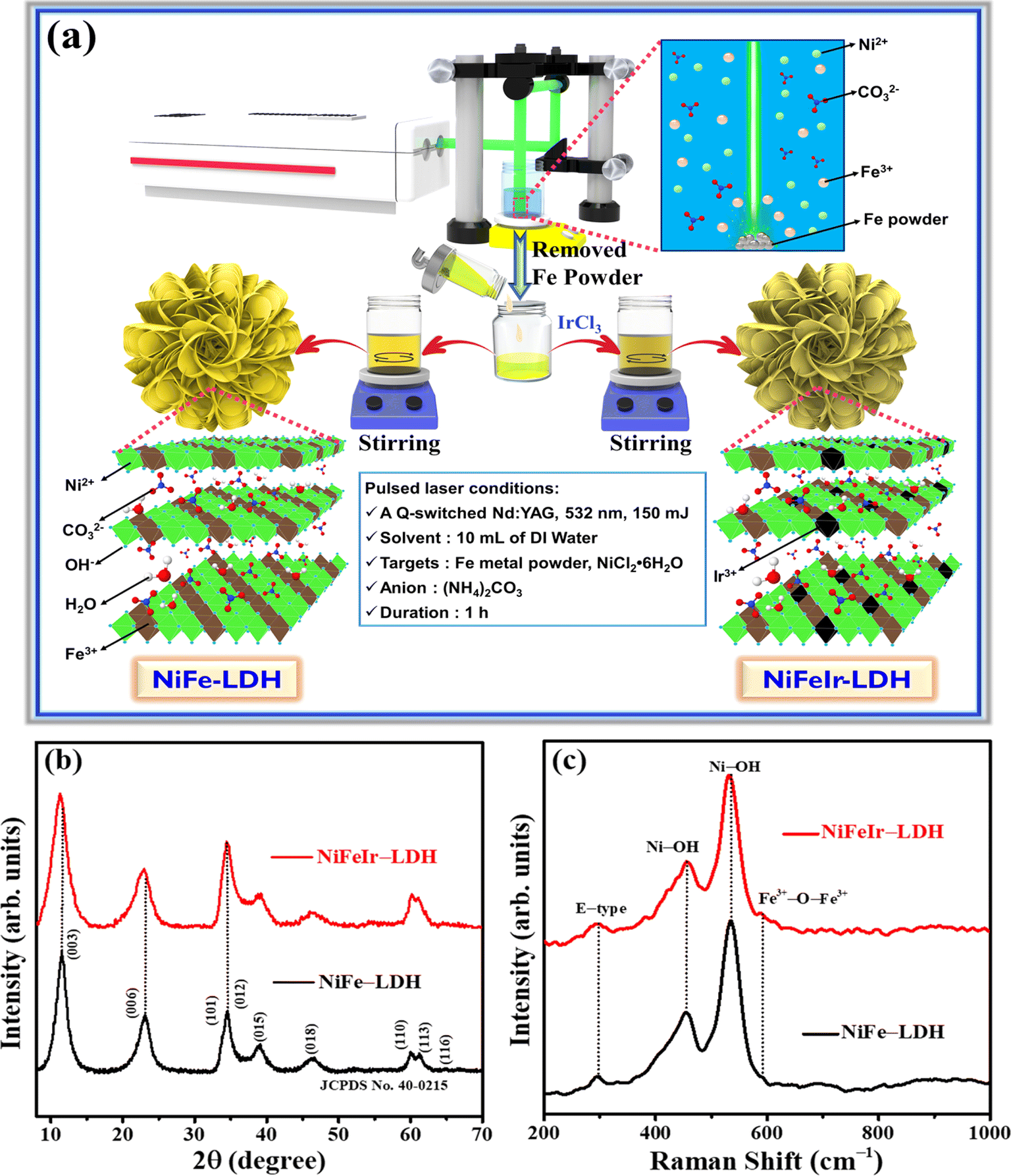 | ||
| Fig. 1 (a) Schematic diagram of the synthesis of flower-like NiFeIr-LDH nanosheets using an advanced PLI method, and (b) XRD patterns and (c) Raman spectra of the as-synthesized NiFe-LDH and NiFeIr-LDH nanosheets. | ||
The X-ray diffraction (XRD) patterns of the as-synthesized samples, depicted in Fig. 1b, corroborate that the diffraction peaks of NiFe-LDH are in good agreement with the crystalline structure of NiFe-LDH (JCPDS card no. 40-0215).33,35 Following the incorporation of Ir into NiFe-LDH, the absence of new diffraction peaks and the observed shift of existing NiFe-LDH peaks toward lower 2θ values, as detailed in the magnified XRD patterns in Fig. S2,† unequivocally demonstrates the effective doping of Ir, while preserving the original host phase. Additionally, these shifts affirm the purity of the as-synthesized samples. Meanwhile, the XRD pattern of the as-synthesized NiFeIr-LDHCop, shown in Fig. S3,† also well matches the diffraction peaks of NiFe-LDH. On the other hand, the Raman spectra of the as-synthesized NiFe-LDH and NiFeIr-LDH nanosheets, shown in Fig. 1c, reveal that both types of nanosheets exhibit similar characteristic peaks, consistent with previous reports on NiFe-LDH materials.28,48 Specifically, the NiFe-LDH nanosheets show characteristic peaks at 295, 455, 533, and 588 cm−1, which can be credited to the stretching vibrations of E-type, Ni–OH, disordered Ni–OH, and Fe3+–O–Fe3+, respectively. However, in the case of NiFeIr-LDH nanosheets, these peak positions have slightly shifted to lower values (Fig. S4†), indicating the effective influence of Ir doping on NiFe-LDH nanosheets. Additionally, the synthesized NiFeIr-LDHCop exhibits the same Raman spectrum as NiFe-LDH, as presented in Fig. S5.† Furthermore, the doping of Ir is anticipated to enhance the availability of active sites on the NiFe-LDH nanosheets, thereby enhancing their electrocatalytic activity for the OER.
Scanning electron microscopy (SEM) and high-resolution transmission electron microscopy (HR-TEM) characterization studies of the as-synthesized samples are depicted in Fig. 2a–n. SEM images (Fig. 2a and b) reveal that NiFe-LDH exhibits a flower-like morphology, composed of interconnected nanosheets. Similarly, NiFeIr-LDH retains this morphology (Fig. 2c and d), indicating that Ir doping into the NiFe-LDH structure does not alter its surface morphology. SEM-EDS mapping for analyzing the elemental compositions of the as-synthesized samples revealed uniform distributions of Ni (26.99 wt%), Fe (5.87 wt%), C (27.55 wt%), and O (39.60 wt%) in the NiFe-LDH nanosheets (Fig. 2e and S6a†). Specifically, the uniform distribution of Ni (25.44 wt%), Fe (4.72 wt%), C (24.05 wt%), and O (40.91 wt%) along with Ir (4.87 wt%) in the NiFeIr-LDH nanosheets (Fig. 2f and S6b†) supported our claim of effective Ir doping into NiFe-LDH. Notably, the low Ir content (∼4.87 wt%) in NiFeIr-LDH nanosheets underscores their potential cost-effectiveness for large-scale applications. Additionally, NiFeIr-LDHCop samples, as illustrated in Fig. S7a–c,† displayed the presence of Ni, Fe, Ir, C, and O elements, yet lacked the uniform flower-shaped morphology characteristic of samples synthesized via the PLI approach, highlighting the unique capability of the PLI method for producing uniformly structured LDH materials. The HR-TEM characterization of the as-synthesized NiFe-LDH and NiFeIr-LDH nanosheets was performed and the resultant HR-TEM micrographs are shown in Fig. 2g–n. HR-TEM images of NiFe-LDH at various magnifications, shown in Fig. 2g–j, also revealed its interconnected nanosheet-like morphology with interplanar spacings of 0.20 and 0.25 nm assigned to the (018) and (012) planes of NiFe-LDH, respectively.28,35 Meanwhile, Fig. 2k–n show that NiFeIr-LDH also preserved the interconnected nanosheet-like structure with interplanar spacings of 0.20 and 0.25 nm corresponding to the (018) and (012) planes of NiFe-LDH, respectively.33 Additionally, the HR-TEM images in Fig. S8a–d† reveal an interconnected nanosheet-like morphology for NiFeIr-LDHCop, with similar interplanar spacings to those seen in NiFe-LDH. Previous studies suggest that doping Ir into NiFe-LDH nanosheets helps increase the surface reactive sites and enhances the electrical conductivity, both of which are likely to promote the electrochemical performance of the OER.40,42
 | ||
| Fig. 2 (a and b) SEM images, (e) SEM-EDS mapping images and (g–j) HR-TEM images of the NiFe-LDH nanosheets and (c and d) SEM images, (f) SEM-EDS mapping images and (k–n) HR-TEM images of the NiFeIr-LDH nanosheets. | ||
In addition, core-level X-ray photoelectron spectroscopy (XPS) characterization was employed to inspect the elemental compositions and surface oxidation states of the as-synthesized samples, as shown in Fig. S9† and 3a–e. The XPS survey spectra in Fig. S9† show the detection of Ni, Fe, Ir, C, and O elements for NiFeIr-LDH nanosheets, confirming the effective incorporation of Ir into the NiFe-LDH nanosheets. In Fig. 3a, the Ni 2p spectrum can be seen to consist of two core peaks at 856.3 and 874.0 eV along with their satellite peaks, corresponding to the Ni2+ 2p3/2 and Ni2+ 2p1/2 signals, respectively.42,49 At the same time, Fig. 3b confirms that the Fe 2p spectrum also has two core peaks at 712.2 and 724.7 eV with their satellite peaks, corresponding to to the Fe3+ 2p3/2 and Fe3+ 2p1/2 signals, respectively.34,50 Notably, in comparison to NiFe-LDH, the XPS peak positions for Ni2+ 2p3/2, Ni2+ 2p1/2, Fe3+ 2p3/2, and Fe3+ 2p1/2 in NiFe-LDH nanosheets exhibit a slight shift toward higher binding energies, suggesting alterations in the electronic structure of NiFe-LDH attributable to Ir-doping. These modifications could play a crucial role in enhancing the electrocatalytic performance of the OER.33,35 As shown in Fig. 3c, the Ir 4d spectra exhibited two peaks at 297.4 and 312.9 eV for only NiFeIr-LDH, which were associated with the Ir3+ 4d5/2 and Ir3+ 4d3/2 signals, respectively.51,52 This indicates the presence of Ir with an oxidation level of 3+ in NiFe-LDH nanosheets. Besides, the O 1s spectra in Fig. 3d show two peaks at 530.7 and 532.6 eV which were attributed to the M–OH bonds (M = Ni, Fe or Ir) and C–O bonds, respectively.53 Additionally, a slightly positive shift can be observed in the M–OH peak of NiFeIr-LDH as compared to that of NiFe-LDH, revealing a strong interaction of metal cations with the O sites, which might have a role to play in improving the intrinsic activity of the OER.33 In Fig. 3e, the C 1s spectrum exhibits three peaks at around 284.6, 286.2, and 288.5 eV associated with the C–C, C![[double bond, length as m-dash]](https://www.rsc.org/images/entities/char_e001.gif) O, and OC–O bonds from the carbonyl (CO32−) anions of LDH, respectively.54,55 To get a better understanding of the electronic structure and coordination environment of Ir species, we conducted X-ray absorption spectroscopy (XAS) on the NiFeIr-LDH sample. Fig. 3f displays the X-ray absorption near-edge structure (XANES) spectra of the Ir K-edge for NiFeIr-LDH with Ir foil as the reference. Notably, the intensity of the normalized XANES spectrum at the Ir L3-edge of NiFeIr-LDH is significantly higher compared to that of Ir foil. This suggests an enhanced local coordination environment of Ir species, possibly due to the presence of higher oxidation Ir species within the NiFeIr-LDH structure.56,57 The Fourier transform (FT) extended X-ray absorption fine structure (EXAFS) plots of NiFeIr-LDH with Ir foil as the reference are illustrated in Fig. 3g. These spectra confirm a noticeable difference in the R space of NiFeIr-LDH compared to that of Ir foil, indicating a distinct coordination environment for Ir species within NiFeIr-LDH.58 In particular, the distinct peaks at 1.66 Å and 2.83 Å in NiFeIr-LDH indicate the presence of Ir–O and Ir–Ni/Fe coordination, respectively.59,60 In contrast, Ir foil exhibits a strong Ir–Ir signal exclusively in the wavelet transforms of the EXAFS signal (Fig. 3h). However, as illustrated in Fig. 3i, the synthesized NiFeIr-LDH nanosheets display both Ir–O and Ir–Ni/Fe signals in their wavelet transforms of the EXAFS signal. These XAS results provide compelling evidence for the presence of Ir species with a higher oxidation state incorporated into the lattice of the NiFe-LDH structure. Overall, these characterization results demonstrated the successful synthesis of Ir-doped NiFe-LDH nanosheets via a simple and time-saving PLI approach.
O, and OC–O bonds from the carbonyl (CO32−) anions of LDH, respectively.54,55 To get a better understanding of the electronic structure and coordination environment of Ir species, we conducted X-ray absorption spectroscopy (XAS) on the NiFeIr-LDH sample. Fig. 3f displays the X-ray absorption near-edge structure (XANES) spectra of the Ir K-edge for NiFeIr-LDH with Ir foil as the reference. Notably, the intensity of the normalized XANES spectrum at the Ir L3-edge of NiFeIr-LDH is significantly higher compared to that of Ir foil. This suggests an enhanced local coordination environment of Ir species, possibly due to the presence of higher oxidation Ir species within the NiFeIr-LDH structure.56,57 The Fourier transform (FT) extended X-ray absorption fine structure (EXAFS) plots of NiFeIr-LDH with Ir foil as the reference are illustrated in Fig. 3g. These spectra confirm a noticeable difference in the R space of NiFeIr-LDH compared to that of Ir foil, indicating a distinct coordination environment for Ir species within NiFeIr-LDH.58 In particular, the distinct peaks at 1.66 Å and 2.83 Å in NiFeIr-LDH indicate the presence of Ir–O and Ir–Ni/Fe coordination, respectively.59,60 In contrast, Ir foil exhibits a strong Ir–Ir signal exclusively in the wavelet transforms of the EXAFS signal (Fig. 3h). However, as illustrated in Fig. 3i, the synthesized NiFeIr-LDH nanosheets display both Ir–O and Ir–Ni/Fe signals in their wavelet transforms of the EXAFS signal. These XAS results provide compelling evidence for the presence of Ir species with a higher oxidation state incorporated into the lattice of the NiFe-LDH structure. Overall, these characterization results demonstrated the successful synthesis of Ir-doped NiFe-LDH nanosheets via a simple and time-saving PLI approach.
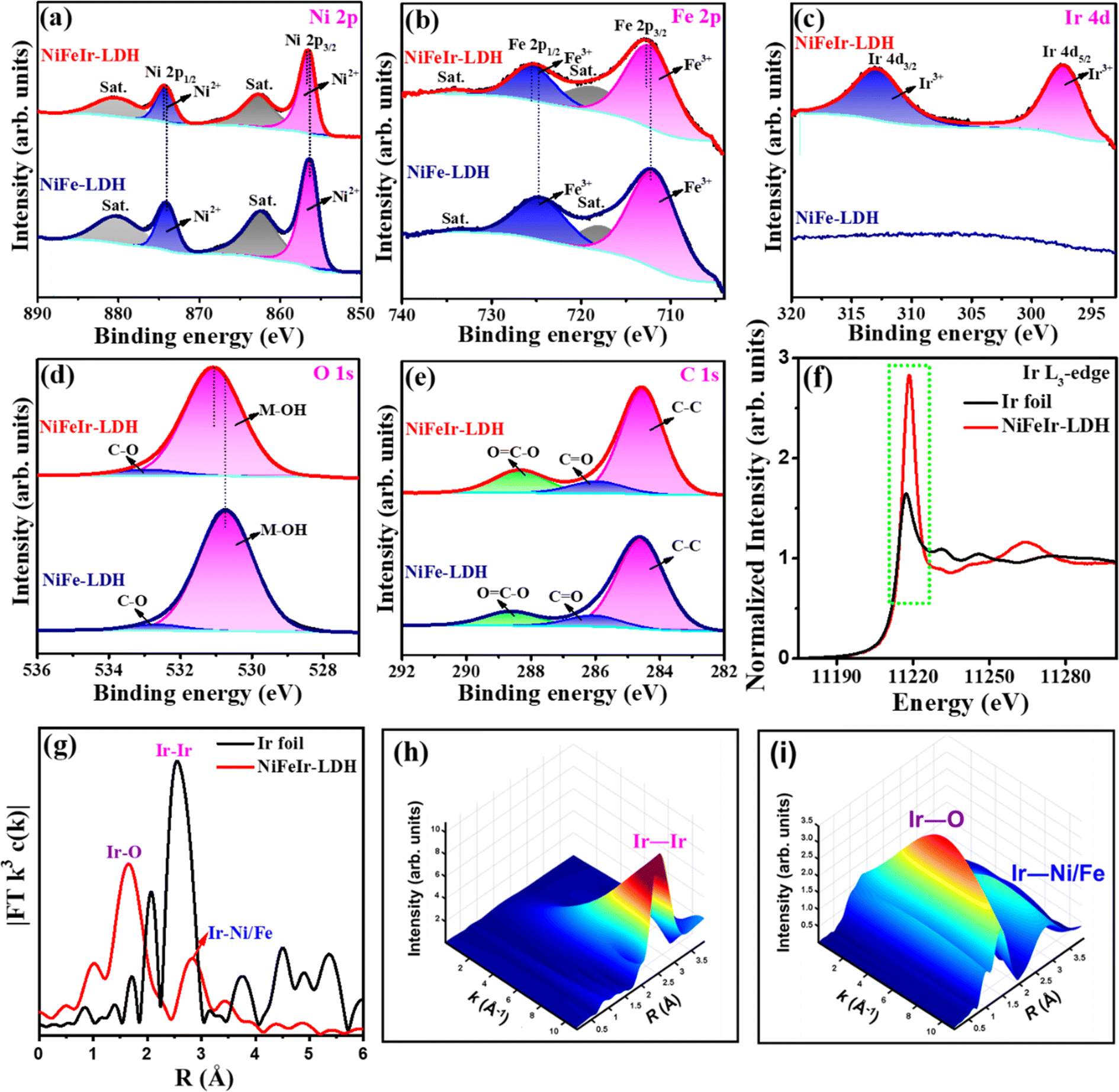 | ||
| Fig. 3 XPS spectra of the as-synthesized NiFe-LDH and NiFeIr-LDH nanosheets: (a) Ni 2p, (b) Fe 2p, (c) Ir 4d, (d) O 1s and (e) C 1s. (f) Ir L3-edge XANES spectra and (g) the corresponding Fourier transforms of Ir L3-edge EXAFS spectra of the as-synthesized NiFeIr-LDH nanosheets and the standard reference Ir foil. Wavelet transforms of the EXAFS signals for the (h) standard reference Ir foil and (i) NiFeIr-LDH nanosheets. | ||
3.2. Electrocatalytic OER performance
The electrocatalytic OER performance of the as-synthesized NiFe-LDH, NiFeIr-LDH, and NiFeIr-LDHCop nanosheets was evaluated in a 1 M KOH electrolyte using a standard three-electrode system (Fig. S10†). For comparison, the OER activity of a commercial IrO2 catalyst was also verified. Linear sweep voltammetry (LSV) curves, presented in Fig. 4a, indicate that the NiFeIr-LDH nanosheets synthesized via the PLI method demonstrate superior OER performance compared to NiFe-LDH, NiFeIr-LDHCop, and the commercial IrO2 catalyst. The absence of an oxidation peak in NiFeIr-LDH, in contrast to NiFeIr-LDHCop, may be attributed to Ni atoms on the LDH surface existing in slightly higher oxidation states. Notably, as shown in Fig. 4b, NiFeIr-LDH nanosheets exhibit significantly lower overpotentials of 246 and 384 mV at current densities of 10 and 50 mA cm−2, respectively, in comparison to NiFe-LDH (345 and 484 mV), NiFeIr-LDHCop (261 and 451 mV), and IrO2 (327 and 480 mV). These findings underscore the profound impact of Ir doping into NiFe-LDH nanosheets via the PLI method on enhancing OER performance, even at low doping concentrations. This enhancement is likely due to the increased exposure of active sites and the synergistic electronic effect between the doped Ir and NiFe-LDH matrix. Importantly, the Tafel slope is the most significant parameter for evaluating the reaction kinetics of an OER catalyst.61 To better understand the reason for the increased OER performance of NiFeIr-LDH nanosheets, the Tafel plots obtained from the LSV plots are presented in Fig. 4c. It is evident that the NiFeIr-LDH nanosheets displayed the smallest Tafel slope of 46 mV dec−1 compared to those of NiFe-LDH (80 mV dec−1), NiFeIr-LDHCop (58 mV dec−1), and IrO2 (77 mV dec−1). This indicates enhanced reaction kinetics for NiFeIr-LDH, resulting in superior OER performance. On the other hand, the mass activity and turnover frequency (TOF) of the as-synthesized samples were also determined to know their intrinsic activity for the OER.62Fig. 4d shows that NiFeIr-LDH exhibited the highest mass activity values at each overpotential. Notably, NiFeIr-LDH had the highest mass activity value of 47.04 A g−1 at an overpotential of 350 mV compared to NiFe-LDH (17.65 A g−1), NiFeIr-LDHCop (23.67 A g−1), and IrO2 (20.51 A g−1). This indicates that the doping of Ir into NiFe-LDH through PLI significantly improved the intrinsic activity of NiFe-LDH for the OER. Meanwhile, the number of surface-active sites was determined from the reduction part of the cyclic voltammetry (CV) curves measured at 50 mV s−1 (Fig. S11a–d†) for determining the TOF.2,63 The TOF values determined are presented in Fig. 4e. It is also worth noting that NiFeIr-LDH showed the highest TOF values at each overpotential. For instance, the TOF value of NiFeIr-LDH was found to be 0.288 s−1 at an overpotential of 350 mV, which is higher compared to that of NiFe-LDH (0.190 s−1), NiFeIr-LDHCop (0.189 s−1), and IrO2 (0.105 s−1). This higher TOF value ensures the availability and accessibility of efficient surface-active sites for the electrochemical OER at any given instant during the reaction, demonstrating the excellent intrinsic catalytic nature of NiFeIr-LDH for the OER.18 Thus, the higher OER activity of NiFeIr-LDH might be credited to its unique 2D nanosheet structure enabling quick mass transport and the electronic contacts between the doped Ir and Ni/Fe enabling access to more metal active sites, thus aiding the OER kinetics.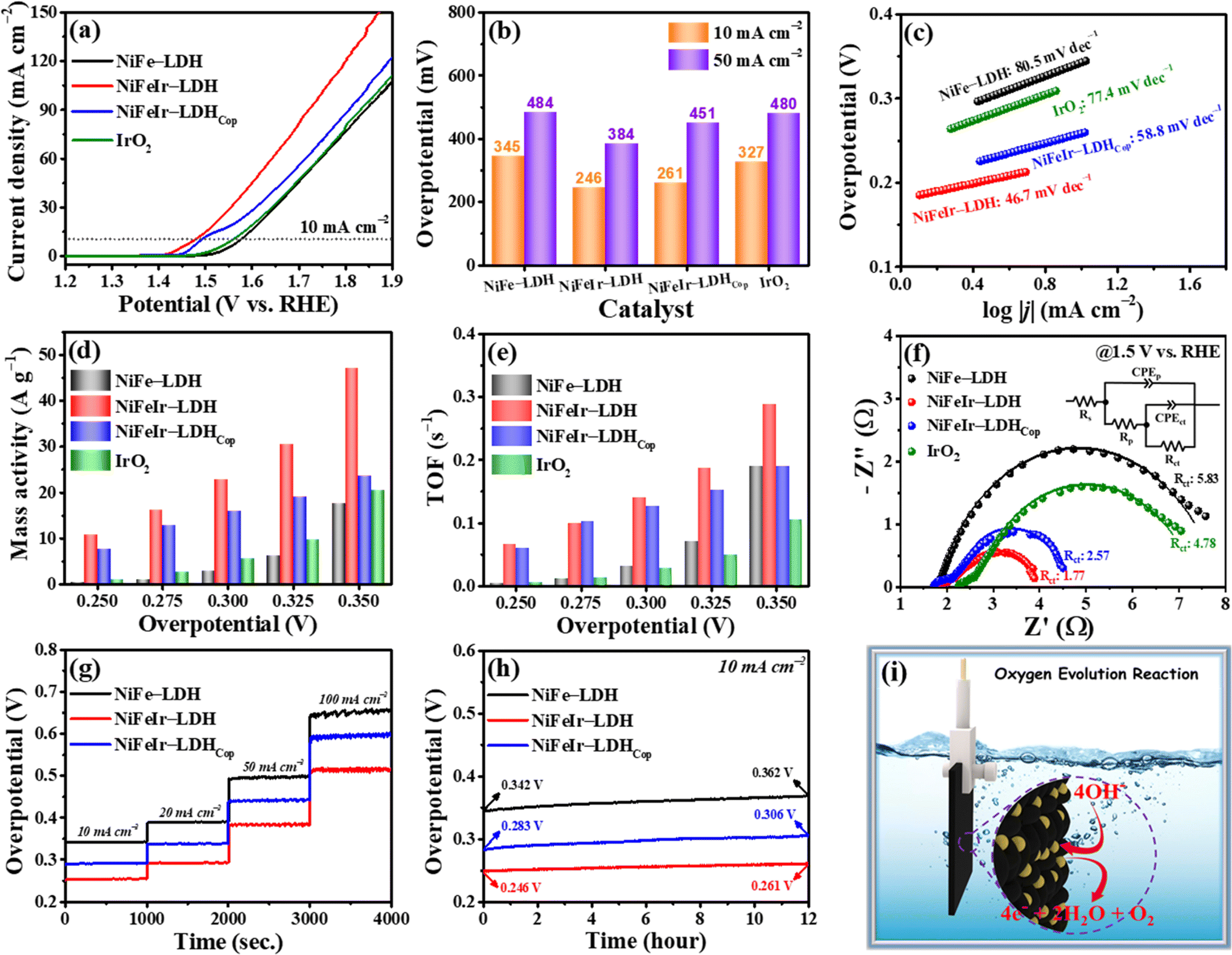 | ||
| Fig. 4 OER performances in a 1 M KOH electrolyte: (a) LSV polarization curves, (b) overpotentials at 10 and 50 mA cm−2, (c) Tafel plots, (d) mass activities, (e) TOF activities, and (f) Nyquist plots of the as-synthesized NiFe-LDH, NiFeIr-LDH and NiFeIr-LDHCop nanosheets along with a commercial IrO2 catalyst. (g) Step-wise CP tests and (h) long-term OER stability tests of NiFe-LDH, NiFeIr-LDH, and NiFeIr-LDHCop nanosheets. (i) A schematic diagram for the OER mechanism at the electrode surface in an alkaline electrolyte. | ||
To gain a better understanding of the electron transfer kinetics, electrochemical impedance spectroscopy (EIS) characterization was also conducted during the OER.53,64 The Nyquist plots, obtained at a stable potential of 1.5 V vs. RHE and fitted with an equivalent circuit, are illustrated in Fig. 4f. The resistance in the high-frequency region corresponds to the solution resistance (Rs), while the resistance in the low-frequency region is associated with the charge transfer resistance (Rct) of OH− ion adsorption. From these fitted Nyquist plots, it was observed that NiFeIr-LDH exhibited the lowest Rct of 1.77 Ω, compared to NiFe-LDH (5.83 Ω), NiFeIr-LDHCop (2.57 Ω), and IrO2 (4.78 Ω). These results showed that NiFeIr-LDH could accomplish a much faster charge transfer between the electrodes and electrolyte due to its good electrical conductivity, which is in good agreement with the Tafel slopes discussed earlier, leading to a better OER performance. The Bode plots can be derived from EIS measurements to determine the electron lifetimes (τe) in the OER, as presented in Fig. S12.† The τe value was assessed using the expression τe = 1/2πfmax, where fmax denotes the maximum frequency. The low τe value (64 ms) of NiFeIr-LDH represents its small electron relaxation time, which could be helpful in improving the reaction kinetics of the OER. Fig. S13† displays the Nyquist plots of NiFeIr-LDH during the OER at various overpotentials ranging from 250 to 290 mV. These plots indicate that the charge-transfer process increases with increasing applied overpotential. The electrochemical surface areas (ECSAs) were analyzed by testing the double-layer capacitance (Cdl) in the non-faradaic region to further verify the improved OER performance of NiFeIr-LDH.30,65 To calculate the value of Cdl, CV curves were measured for NiFe-LDH, NiFeIr-LDH, and NiFeIr-LDHCop in the range of 0.95–1.05 V vs. RHE at scan rates ranging from 10 to 100 mV s−1, as depicted in Fig. S14a–c.† The plots of (ΔJ)/2 versus the scan rates, shown in Fig. S14d,† indicate that NiFeIr-LDH presented a Cdl value of 4.33 mF cm−2, higher than those of NiFe-LDH (2.07 mF cm−2) and NiFeIr-LDHCop (4.21 mF cm−2). In addition, Fig. S15† shows that NiFeIr-LDH had a higher ECSA of 0.049 cm2 compared to NiFe-LDH (0.024 cm2) and NiFeIr-LDHCop (0.047 cm2). This demonstrates that NiFeIr-LDH can expose more electrochemically active sites to the electrolyte during the electrochemical reaction. Consequently, the electrocatalytic OER activity of PLI produced NiFe-LDH significantly improved due to Ir doping. Moreover, the ECSA normalized LSV curves for the OER process in Fig. S16† indicate that an increase in surface area leads to an enhanced current response during the OER process, resulting in increased intrinsic activity. These results could be attributed to the enhanced effective charge transport and increased number of active sites from its unique 2D nanosheet structure, enhanced ECSA, good electrical conductivity, and the synergistic interaction between the doped Ir and the Ni/Fe cations.
The long-term stability of electrocatalytic materials is the most significant factor determining their suitability for practical application.9,66 Therefore, the long-term OER stabilities of the as-synthesized NiFe-LDH, NiFeIr-LDH and NiFeIr-LDHCop nanosheets were tested using the chronopotentiometry (CP) technique. The step-wise CP testing results, as presented in Fig. 4g, demonstrate an increase in the OER overpotential with the increase in current density from 10 to 100 mA cm−2 for both samples. More interestingly, the NiFeIr-LDH nanosheets kept the OER overpotentials stable at 246, 296, 387, and 519 mV at 10, 20, 50, and 100 mA cm−2, respectively, which is in good agreement with LSV plots, confirming the good catalyst stability. As shown in Fig. 4h, NiFeIr-LDH displayed a negligible overpotential increase (only 15 mV) after a continuous OER test for 12 h. Subsequently, Fig. S17† demonstrates that after 50 h of continuous OER testing, the overpotential increase for NiFeIr-LDH was merely 46 mV, showcasing its exceptional long-term OER stability. Additionally, the SEM images in Fig. S18a–c† show no noticeable morphological changes in NiFeIr-LDH after the 12 h OER stability test. HR-TEM images in Fig. S19† affirm that NiFeIr-LDH retains its 2D nanosheet structure post 12 h of OER stability testing, emphasizing its remarkable structural stability under OER conditions. Fig. S20† indicates the emergence of new peaks corresponding to γ-NiOOH in the XRD pattern of NiFeIr-LDH following OER stability testing, indicating the formation of surface active γ-NiOOH species during the OER. Similarly, the ex situ Raman spectra shown in Fig. S21† further suggest the surface transformation of NiFeIr-LDH into active γ-NiOOH and Ir–O species after the OER stability test.51 This confirms the formation of higher valence states of Ni3+ and Ir4+ due to the oxidation of Ni2+ and Ir3+, respectively, during the OER process. A schematic diagram for the electrochemical OER mechanism at the electrode surface in an alkaline electrolyte, based on the above results, is presented in Fig. 4i. Moreover, the overall electrochemical performances of the NiFe-LDH and NiFeIr-LDH electrocatalysts for the OER are summarized in Table S1.† Interestingly, NiFeIr-LDH offered a low overpotential (246 mV at 10 mA cm−2) and a low Tafel slope (46 mV dec−1) with proven OER stability for 12 h. This remarkable improvement in the OER performance is achieved through the doping of Ir into NiFe-LDH nanosheets, which benefits from accelerated reaction kinetics and superb electrical conductivity. Amazingly, our NiFeIr-LDH nanosheets exhibit better OER performance than previously reported OER electrocatalysts (Table S2†), showing the PLI method is a promising synthesis technology for developing 2D nanomaterials for energy applications.
Encouraged by the excellent OER performance of the synthesized NiFeIr-LDH nanosheets, an alkaline water electrolyzer was fabricated with NiFeIr-LDH as the anode and commercial 20% Pt/C as the cathode using a 1 M KOH solution as the electrolyte for performing OWS to confirm their practical application (Fig. S22†). At the same time, the OWS performance was also tested on the IrO2(+)∥Pt/C(−) electrolyzer for comparison. The LSV curves at 5 mV s−1 presented in Fig. 5a demonstrate that the NiFeIr-LDH(+)∥Pt/C(−) electrolyzer shows an enhanced OWS performance as compared to the benchmark IrO2(+)∥Pt/C(−) electrolyzer. Specifically, the NiFeIr-LDH(+)∥Pt/C(−) electrolyzer only required a cell voltage of 1.53 V to produce a current density of 10 mA cm−2, which is lower than that of the IrO2(+)∥Pt/C(−) electrolyzer (1.62 V), as shown in Fig. 5b. This shows the excellent OWS response of the NiFeIr-LDH(+)∥Pt/C(−) electrolyzer. In addition, Fig. 5c suggests that the NiFeIr-LDH(+)∥Pt/C(−) electrolyzer can maintain stable cell voltages of 1.53, 1.61, 1.80, and 2.08 V when performing stepwise CP measurements at 10, 20, 50, and 100 mA cm−2, respectively. In particular, there were no significant changes observed in the cell voltage of the NiFeIr-LDH(+)∥Pt/C(−) electrolyzer even after 12 h of continuous operations (Fig. 5d), ensuring excellent long-term stability. Furthermore, we quantified the amount of hydrogen gas generated by the NiFeIr-LDH(+)∥Pt/C(−) electrolyzer during the OWS process using gas chromatography. As seen in Fig. 5e, the NiFeIr-LDH(+)∥Pt/C(−) electrolyzer produced 1.028 mmol of hydrogen at an applied cell voltage of 2 V within 60 min. This production level is notably higher than that of the benchmark electrolyzer (0.639 mmol). Subsequently, hydrogen production from the NiFeIr-LDH(+)∥Pt/C(−) electrolyzer increased as the applied cell voltage ranged from 1.6 to 2.2 V (Fig. S23†). A schematic diagram of the as-fabricated NiFeIr-LDH(+)∥Pt/C(−) electrolyzer is displayed in Fig. 5f. These results underscore that the NiFeIr-LDH nanosheets from the PLI approach have great potential as OER electrocatalysts to be used in alkaline water electrolyzers.
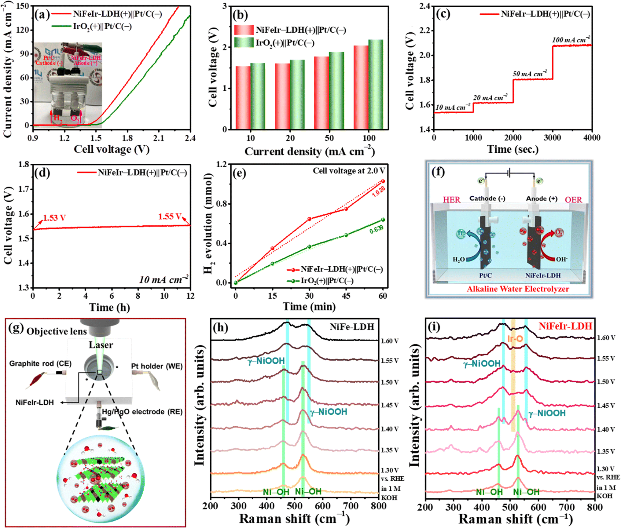 | ||
| Fig. 5 OWS performance of the assembled alkaline water electrolyzer with a NiFeIr-LDH(+)∥Pt/C(−) system: (a) LSV polarization curves (inset shows an optical image of the OWS electrolyzer), (b) the required cell voltage to supply 10, 20, 50 and 100 mA cm−2, (c) step-wise CP test, (d) long-term OWS stability, (e) the quantification of hydrogen production at an applied cell voltage of 2 V and (f) a schematic diagram of the alkaline water electrolyzer. (g) Schematic representation of the in situ/operando Raman spectroscopy cell setup, and (h and i) in situ/operando Raman spectra recorded during the OER process of (h) NiFe-LDH and (i) of NiFeIr-LDH nanosheets. | ||
3.3. In situ/operando Raman spectroscopy studies
To get detailed insights into the origin of OER performance improvement in the NiFeIr-LDH nanosheets, in situ/operando Raman spectroscopy was conducted to identify surface intermediates during the OER.48,67 Fig. S24† displays the digital photos of the in situ/operando Raman spectroscopy setup. Likewise, a schematic illustration of the in situ/operando Raman spectroscopy examination of NiFeIr-LDH during the OER is presented in Fig. 5g. We conducted a series of Raman spectroscopy measurements for both NiFe-LDH and NiFeIr-LDH nanosheets during the OER at different potentials ranging from 1.30 to 1.60 V vs. RHE, as shown in Fig. 5h and i, respectively. In the OER at potentials within 1.30 and 1.40 V vs. RHE, two distinct Raman peaks at 457 and 529 cm−1 were observed, corresponding to the characteristic bands of NiFe-LDH. However, as the potential exceeded 1.40 V vs. RHE, two new Raman peaks at 472 and 547 cm−1 emerged in both NiFe-LDH and NiFeIr-LDH nanosheets, indicating the presence of characteristic bands associated with γ-NiOOH species.38,68 Significantly, the intensities of these Raman peaks associated with γ-NiOOH were notably higher in the case of NiFeIr-LDH compared to NiFe-LDH. Furthermore, NiFeIr-LDH nanosheets exhibited a new peak at 512 cm−1 with lower intensity at higher potentials, which can be ascribed to the characteristic band of Ir–O species.51 These results provide evidence for the transformation of NiFeIr-LDH into γ-NiOOH and Ir–O species, affirming the surface oxidation of Ni2+ and Ir3+ into higher valence states of Ni3+ and Ir4+ during the OER process. Thus, the in situ/operando Raman spectroscopy studies revealed the formation of surface-active γ-NiOOH and Ir–O intermediates, which act as active catalytic sites to increase the OER activity of NiFeIr-LDH nanosheets.3.4. Theoretical calculations through DFT studies
Electrochemical measurements have empirically validated the enhancement of the OER activity of NiFe-LDH through the incorporation of Ir dopants. To better understand the enhanced OER activity of NiFeIr-LDH, we conducted a theoretical investigation using density functional theory (DFT) to compute the Gibbs free energy changes during the OER process.69,70Fig. 6a displays the side and top-view crystal structures of NiFeIr-LDH, highlighting the incorporation of Ir dopants within the NiFe-LDH lattice. Fig. 6b shows the charge density changes in NiFeIr-LDH, demonstrating the effective modulation of charge redistribution resulting from the incorporation of Ir. This observation suggests a significant electronic interaction between the doped Ir sites and the NiFe-LDH matrix.59 The total density of states (DOS) for both NiFe-LDH and NiFeIr-LDH is presented in Fig. 6c. It becomes evident that the incorporation of Ir atoms induces alterations in the electronic states of NiFeIr-LDH, resulting in an increase in DOS near the Fermi level. This observed change in the electronic structure of NiFeIr-LDH contributes to its superior electronic conductivity when compared to pure NiFe-LDH. This augmented electronic conductivity, in turn, facilitates enhanced charge transfer between active sites and surface adsorbed intermediates, thus leading to the boosted OER performance of NiFeIr-LDH.71 Furthermore, Fig. 6d presents the Gibbs free energy changes for OER intermediates, such as *OH, *O, and *OOH, for both NiFe-LDH and NiFeIr-LDH. Notably, the conversion from *OH to *O represents the rate-determining step (RDS) for both NiFe-LDH and NiFeIr-LDH in the OER process, as indicated by a substantial change in Gibbs free energy (ΔG). Particularly, the ΔG value for NiFeIr-LDH stands at 2.32 eV, markedly lower than that of NiFe LDH (2.65 eV). This reduced energy barrier of NiFeIr-LDH implies a lower theoretical overpotential requirement for the OER process, resulting in enhanced OER activity compared to NiFe-LDH.38,72Fig. 6e illustrates the proposed catalytic OER mechanism on NiFeIr-LDH nanosheets, identifying the Fe site as the primary active site.28 The mechanism begins with the active surface sites (*) adsorbing a hydroxyl anion (OH−) from the electrolyte, leading to the formation of *OH via electron loss. This *OH species then interacts with another OH−, converting into *O by releasing a water molecule and an electron. The subsequent step involves the *O species coupling with another OH− to form the *OOH species through electron loss. The OER process culminates with the *OOH species reacting with OH− to produce O2, alongside the release of a water molecule and an electron, illustrating the four single electron transfer steps integral to the OER. Consequently, the results of our DFT calculations propose that the increased OER performance of NiFeIr-LDH can be attributed to the creation of electronic contacts between the doped Ir atoms and the Ni and Fe atoms within NiFeIr-LDH as well as a noticeably reduced energy barrier towards the OER. Furthermore, it should be noted that the NiFeIr-LDH nanosheets have many more active metal sites and enlarged ECSA as compared to NiFe-LDH, which enables the adsorption of OH− to accelerate the OER kinetics.38,40 Therefore, the NiFeIr-LDH nanosheets produced by PLI could potentially be a reliable electrocatalyst for oxygen evolution for energy applications in the future. | ||
| Fig. 6 (a) DFT-optimized top and side view crystal structures of NiFeIr-LDH, (b) charge density difference over NiFeIr-LDH, (c) DOS of NiFe-LDH and NiFeIr-LDH (Fermi level is set as 0 eV), (d) Gibbs free energy diagrams of the four-electron OER process for the NiFe-LDH and NiFeIr-LDH catalysts at an applied overpotential of 1.23 V vs. RHE and (e) the proposed four-electron OER mechanism for the NiFeIr-LDH catalyst with Fe as the main active site. | ||
4. Conclusions
In conclusion, we have proposed a novel and time-saving PLI approach for the successful construction of NiFeIr-LDH nanosheets as an efficient and durable OER electrocatalyst in a strong alkaline electrolyte. The NiFeIr-LDH nanosheets exhibited a superior OER activity with a substantially decreased overpotential (246 mV at 10 mA cm−2) and Tafel slope (46 mV dec−1) as compared to NiFe-LDH (345 mV, 80 mV dec−1) and IrO2 (327 mV, 77 mV dec−1). Likewise, the NiFeIr-LDH nanosheets demonstrated an amazing long-term durability of at least 12 h during the OER. The unique 2D surface structure, increased metal active sites, efficient mass transport, enlarged ECSA, and excellent electrical conductivity were identified as contributing factors to the exceptional OER performance of the NiFeIr-LDH nanosheets. Moreover, the findings from in situ/operando Raman spectroscopy and DFT calculations have further substantiated the pivotal role of doped Ir in modulating the electronic structure of NiFe-LDH. These modifications are responsible for the reduced overpotential and enhanced kinetics observed during the OER. Importantly, the designed alkaline water electrolyzer with NiFeIr-LDH(+)∥Pt/C(−) needed only 1.53 V to produce 10 mA cm−2, which is lower compared to that needed by IrO2(+)∥Pt/C(−) (1.62 V at 10 mA cm−2). We trust that this study provides effective insights into the development of more efficient OER electrocatalysts for practical applications such as high-performance water electrolyzers.Conflicts of interest
No conflict to declare.Acknowledgements
This research was supported by Korea Basic Science Institute (National Research Facilities and Equipment Center) grant funded by the Ministry of Education. (No. 2019R1A6C1010042, 2021R1A6C103A427). The authors acknowledge the financial support from National Research Foundation of Korea (NRF), (2022R1A2C2010686, 2022R1A4A3033528, 2022R1I1A1A01073299, 2021R1C1C2010726).References
- C. Zhu, A.-L. Wang, W. Xiao, D. Chao, X. Zhang, N. H. Tiep, S. Chen, J. Kang, X. Wang, J. Ding, J. Wang, H. Zhang and H. J. Fan, Adv. Mater., 2018, 30, 1705516 CrossRef PubMed.
- Y. Yu, S. J. Lee, J. Theerthagiri, Y. Lee and M. Y. Choi, Appl. Catal., B, 2022, 316, 121603 CrossRef CAS.
- C. Xu, M. Zhang, X. Yin, Q. Gao, S. Jiang, J. Cheng, X. Kong, B. Liu and H.-Q. Peng, J. Mater. Chem. A, 2023, 11, 18502–18529 RSC.
- A. Boretti and B. K. Banik, Adv. Energy Sustainability Res., 2021, 2, 2100097 CrossRef CAS.
- C. S. Martavaltzi, E. P. Pampaka, E. S. Korkakaki and A. A. Lemonidou, Energy Fuels, 2010, 24, 2589–2595 CrossRef CAS.
- S. N. Shreyanka, J. Theerthagiri, S. J. Lee, Y. Yu and M. Y. Choi, Chem. Eng. J., 2022, 446, 137045 CrossRef.
- R. A. Senthil, Y. Wang, S. Osman, J. Pan, Y. Lin, X. Shu, X. Jin and Y. Sun, Int. J. Hydrogen Energy, 2019, 44, 16537–16547 CrossRef CAS.
- Y. Ding, K.-W. Cao, J.-W. He, F.-M. Li, H. Huang, P. Chen and Y. Chen, Chin. J. Catal., 2022, 43, 1535–1543 CrossRef CAS.
- Y. Gu, S. Chen, J. Ren, Y. A. Jia, C. Chen, S. Komarneni, D. Yang and X. Yao, ACS Nano, 2018, 12, 245–253 CrossRef CAS PubMed.
- R. A. Senthil, S. Jung, A. Min, C. J. Moon and M. Y. Choi, Chem. Eng. J., 2023, 475, 146441 CrossRef CAS.
- X. Zhang, C. Feng, B. Dong, C. Liu and Y. Chai, Adv. Mater., 2023, 35, 2207066 CrossRef CAS PubMed.
- Q. Xue, X.-Y. Bai, Y. Zhao, Y.-N. Li, T.-J. Wang, H.-Y. Sun, F.-M. Li, P. Chen, P. Jin, S.-B. Yin and Y. Chen, J. Energy Chem., 2022, 65, 94–102 CrossRef CAS.
- N. Yu, Y. Ma, J.-K. Ren, Z.-J. Zhang, H.-J. Liu, J. Nan, Y.-C. Li, Y.-M. Chai and B. Dong, Chem. Eng. J., 2023, 478, 147415 CrossRef CAS.
- S. Li, E. Li, X. An, X. Hao, Z. Jiang and G. Guan, Nanoscale, 2021, 13, 12788–12817 RSC.
- J. Theerthagiri, A. P. Murthy, S. J. Lee, K. Karuppasamy, S. R. Arumugam, Y. Yu, M. M. Hanafiah, H.-S. Kim, V. Mittal and M. Y. Choi, Ceram. Int., 2021, 47, 4404–4425 CrossRef CAS.
- S. Jung, R. A. Senthil, C. J. Moon, N. Tarasenka, A. Min, S. J. Lee, N. Tarasenko and M. Y. Choi, Chem. Eng. J., 2023, 468, 143717 CrossRef CAS.
- H.-J. Liu, R.-N. Luan, L.-Y. Li, R.-Q. Lv, Y.-M. Chai and B. Dong, Chem. Eng. J., 2023, 461, 141714 CrossRef CAS.
- S. S. Naik, J. Theerthagiri, F. S. Nogueira, S. J. Lee, A. Min, G.-A. Kim, G. Maia, L. M. C. Pinto and M. Y. Choi, ACS Catal., 2023, 13, 1477–1491 CrossRef.
- C. Hao, Y. Wu, Y. An, B. Cui, J. Lin, X. Li, D. Wang, M. Jiang, Z. Cheng and S. Hu, Mater. Today Energy, 2019, 12, 453–462 CrossRef.
- Z. Cai, X. Bu, P. Wang, J. C. Ho, J. Yang and X. Wang, J. Mater. Chem. A, 2019, 7, 5069–5089 RSC.
- S. S. Jeon, P. W. Kang, M. Klingenhof, H. Lee, F. Dionigi and P. Strasser, ACS Catal., 2023, 13, 1186–1196 CrossRef CAS.
- R. A. Senthil, J. Pan, X. Yang and Y. Sun, Int. J. Hydrogen Energy, 2018, 43, 21824–21834 CrossRef CAS.
- Y.-N. Zhou, W.-L. Yu, Y.-N. Cao, J. Zhao, B. Dong, Y. Ma, F.-L. Wang, R.-Y. Fan, Y.-L. Zhou and Y.-M. Chai, Appl. Catal., B, 2021, 292, 120150 CrossRef CAS.
- J. Chen, F. Zheng, S.-J. Zhang, A. Fisher, Y. Zhou, Z. Wang, Y. Li, B.-B. Xu, J.-T. Li and S.-G. Sun, ACS Catal., 2018, 8, 11342–11351 CrossRef CAS.
- W.-D. Zhang, Q.-T. Hu, L.-L. Wang, J. Gao, H.-Y. Zhu, X. Yan and Z.-G. Gu, Appl. Catal., B, 2021, 286, 119906 CrossRef CAS.
- J. Zhao, N. Liao and J. Luo, J. Mater. Chem. A, 2023, 11, 9682–9690 RSC.
- Y. Bai, Y. Wu, X. Zhou, Y. Ye, K. Nie, J. Wang, M. Xie, Z. Zhang, Z. Liu, T. Cheng and C. Gao, Nat. Commun., 2022, 13, 6094 CrossRef CAS PubMed.
- S. Liu, H. Zhang, E. Hu, T. Zhu, C. Zhou, Y. Huang, M. Ling, X. Gao and Z. Lin, J. Mater. Chem. A, 2021, 9, 23697–23702 RSC.
- M. Gong, Y. Li, H. Wang, Y. Liang, J. Z. Wu, J. Zhou, J. Wang, T. Regier, F. Wei and H. Dai, J. Am. Chem. Soc., 2013, 135, 8452–8455 CrossRef CAS PubMed.
- L. Yu, H. Zhou, J. Sun, F. Qin, D. Luo, L. Xie, F. Yu, J. Bao, Y. Li, Y. Yu, S. Chen and Z. Ren, Nano Energy, 2017, 41, 327–336 CrossRef CAS.
- H. Xu, B. Wang, C. Shan, P. Xi, W. Liu and Y. Tang, ACS Appl. Mater. Interfaces, 2018, 10, 6336–6345 CrossRef CAS PubMed.
- Y. Wang, L. Yan, K. Dastafkan, C. Zhao, X. Zhao, Y. Xue, J. Huo, S. Li and Q. Zhai, Adv. Mater., 2021, 33, 2006351 CrossRef CAS PubMed.
- X. Wang, Y. Tuo, Y. Zhou, D. Wang, S. Wang and J. Zhang, Chem. Eng. J., 2021, 403, 126297 CrossRef CAS.
- Z. Yin, X. Liu, M. Cui, Z. Cao, A. Liu, L. Gao, T. Ma, S. Chen and Y. Li, Mater. Today Sustain., 2022, 17, 100101 CrossRef.
- H. Sun, W. Zhang, J.-G. Li, Z. Li, X. Ao, K.-H. Xue, K. K. Ostrikov, J. Tang and C. Wang, Appl. Catal., B, 2021, 284, 119740 CrossRef CAS.
- M. Zhang, Y. Liu, B. Liu, Z. Chen, H. Xu and K. Yan, ACS Catal., 2020, 10, 5179–5189 CrossRef CAS.
- Y. Yang, L. Dang, M. J. Shearer, H. Sheng, W. Li, J. Chen, P. Xiao, Y. Zhang, R. J. Hamers and S. Jin, Adv. Energy Mater., 2018, 8, 1703189 CrossRef.
- J. Zhang, J. Liu, L. Xi, Y. Yu, N. Chen, S. Sun, W. Wang, K. M. Lange and B. Zhang, J. Am. Chem. Soc., 2018, 140, 3876–3879 CrossRef CAS PubMed.
- K. Bera, A. Karmakar, S. Kumaravel, S. S. Sankar, R. Madhu, H. N. Dhandapani, S. Nagappan and S. Kundu, Inorg. Chem., 2022, 61, 4502–4512 CrossRef CAS PubMed.
- D. Wang, Q. Li, C. Han, Q. Lu, Z. Xing and X. Yang, Nat. Commun., 2019, 10, 3899 CrossRef PubMed.
- L. Fagiolari, M. Bini, F. Costantino, G. Gatto, A. J. Kropf, F. Marmottini, M. Nocchetti, E. C. Wegener, F. Zaccaria, M. Delferro, R. Vivani and A. Macchioni, ACS Appl. Mater. Interfaces, 2020, 12, 32736–32745 CrossRef CAS PubMed.
- R. Fan, Q. Mu, Z. Wei, Y. Peng and M. Shen, J. Mater. Chem. A, 2020, 8, 9871–9881 RSC.
- J. Liu, J. Xiao, Z. Wang, H. Yuan, Z. Lu, B. Luo, E. Tian and G. I. N. Waterhouse, ACS Catal., 2021, 11, 5386–5395 CrossRef CAS.
- J. Theerthagiri, K. Karuppasamy, S. J. Lee, R. Shwetharani, H.-S. Kim, S. K. K. Pasha, M. Ashokkumar and M. Y. Choi, Light: Sci. Appl., 2022, 11, 250 CrossRef CAS PubMed.
- C. E. Park, H. Lee, R. A. Senthil, G. H. Jeong and M. Y. Choi, Fuel, 2022, 321, 124108 CrossRef CAS.
- R. C. Forsythe, C. P. Cox, M. K. Wilsey and A. M. Müller, Chem. Rev., 2021, 121, 7568–7637 CrossRef CAS PubMed.
- D. Zhang, B. Gökce and S. Barcikowski, Chem. Rev., 2017, 117, 3990–4103 CrossRef CAS PubMed.
- Y. Luo, Y. Wu, D. Wu, C. Huang, D. Xiao, H. Chen, S. Zheng and P. K. Chu, ACS Appl. Mater. Interfaces, 2020, 12, 42850–42858 CrossRef CAS PubMed.
- L. Ding, K. Li, Z. Xie, G. Yang, S. Yu, W. Wang, H. Yu, J. Baxter, H. M. Meyer, D. A. Cullen and F.-Y. Zhang, ACS Appl. Mater. Interfaces, 2021, 13, 20070–20080 CrossRef CAS PubMed.
- R.-Y. Fan, J.-Y. Xie, H.-J. Liu, H.-Y. Wang, M.-X. Li, N. Yu, R.-N. Luan, Y.-M. Chai and B. Dong, Chem. Eng. J., 2022, 431, 134040 CrossRef CAS.
- H. You, D. Wu, D. Si, M. Cao, F. Sun, H. Zhang, H. Wang, T.-F. Liu and R. Cao, J. Am. Chem. Soc., 2022, 144, 9254–9263 CrossRef CAS PubMed.
- S. Li, C. Xi, Y.-Z. Jin, D. Wu, J.-Q. Wang, T. Liu, H.-B. Wang, C.-K. Dong, H. Liu, S. A. Kulinich and X.-W. Du, ACS Energy Lett., 2019, 4, 1823–1829 CrossRef CAS.
- Y. Yang, Q.-N. Yang, Y.-B. Yang, P.-F. Guo, W.-X. Feng, Y. Jia, K. Wang, W.-T. Wang, Z.-H. He and Z.-T. Liu, ACS Catal., 2023, 13, 2771–2779 CrossRef CAS.
- M. Arif, G. Yasin, M. Shakeel, M. A. Mushtaq, W. Ye, X. Fang, S. Ji and D. Yan, Mater. Chem. Front., 2019, 3, 520–531 RSC.
- J. Zhang, X. Ji, N. Ye, H. Zhang, H. Sun, C. Xu, L. Liu, J. Ma and Z. Tong, J. Electrochem. Soc., 2023, 170, 037502 CrossRef CAS.
- Y. Zhao, M. Luo, S. Chu, M. Peng, B. Liu, Q. Wu, P. Liu, F. M. F. de Groot and Y. Tan, Nano Energy, 2019, 59, 146–153 CrossRef CAS.
- J. Guan, D. Li, R. Si, S. Miao, F. Zhang and C. Li, ACS Catal., 2017, 7, 5983–5986 CrossRef CAS.
- W. Xie, G. Zhang, Z. Guo, H. Huang, J. Ye, X. Gao, K. Yue, Y. Wei and L. Zhao, Mater. Today Bio, 2022, 16, 100411 CrossRef CAS PubMed.
- Y. Zhu, J. Wang, T. Koketsu, M. Kroschel, J.-M. Chen, S.-Y. Hsu, G. Henkelman, Z. Hu, P. Strasser and J. Ma, Nat. Commun., 2022, 13, 7754 CrossRef CAS PubMed.
- H. Sun and W. Zhou, Energy Fuels, 2021, 35, 5716–5737 CrossRef CAS.
- Y. Yu, S. J. Lee, J. Theerthagiri, S. Fonseca, L. M. C. Pinto, G. Maia and M. Y. Choi, Chem. Eng. J., 2022, 435, 134790 CrossRef CAS.
- Y. Jeong, S. S. Naik, Y. Yu, J. Theerthagiri, S. J. Lee, P. L. Show, H. C. Choi and M. Y. Choi, J. Mater. Sci. Technol., 2023, 143, 20–29 CrossRef CAS.
- S. Anantharaj, P. E. Karthik and S. Noda, Angew. Chem., Int. Ed., 2021, 60, 23051–23067 CrossRef CAS PubMed.
- R. A. Senthil, J. Pan, Y. Wang, S. Osman, T. R. Kumar and Y. Sun, Ionics, 2020, 26, 6265–6275 CrossRef CAS.
- T. Begildayeva, J. Theerthagiri, S. J. Lee, Y. Yu and M. Y. Choi, Small, 2022, 18, 2204309 CrossRef CAS PubMed.
- M. Etesami, A. A. Mohamad, M. T. Nguyen, T. Yonezawa, R. Pornprasertsuk, A. Somwangthanaroj and S. Kheawhom, J. Alloys Compd., 2021, 889, 161738 CrossRef.
- K. Zhu, X. Zhu and W. Yang, Angew. Chem., Int. Ed., 2019, 58, 1252–1265 CrossRef CAS PubMed.
- Z. Qiu, C.-W. Tai, G. A. Niklasson and T. Edvinsson, Energy Environ. Sci., 2019, 12, 572–581 RSC.
- P. Zhai, M. Xia, Y. Wu, G. Zhang, J. Gao, B. Zhang, S. Cao, Y. Zhang, Z. Li, Z. Fan, C. Wang, X. Zhang, J. T. Miller, L. Sun and J. Hou, Nat. Commun., 2021, 12, 4587 CrossRef CAS PubMed.
- S. Hong, K. Ham, J. Hwang, S. Kang, M. H. Seo, Y.-W. Choi, B. Han, J. Lee and K. Cho, Adv. Funct. Mater., 2023, 33, 2209543 CrossRef CAS.
- X. Ji, Y. Lin, J. Zeng, Z. Ren, Z. Lin, Y. Mu, Y. Qiu and J. Yu, Nat. Commun., 2021, 12, 1380 CrossRef CAS PubMed.
- Z. Xu, Y. Ying, G. Zhang, K. Li, Y. Liu, N. Fu, X. Guo, F. Yu and H. Huang, J. Mater. Chem. A, 2020, 8, 26130–26138 RSC.
Footnotes |
| † Electronic supplementary information (ESI) available. See DOI: https://doi.org/10.1039/d3ta07803e |
| ‡ These authors contributed equally to this work. |
| This journal is © The Royal Society of Chemistry 2024 |