 Open Access Article
Degradation of fluoride in groundwater by electrochemical fixed bed system with bauxite: performance and synergistic catalytic mechanism†
Xiangxu Menga,
Junfeng Li *ab,
Wenying Quab,
Wenhuai Wangab,
Xueting Fenga and
Jiankang Wangab
aCollege of Water Conservancy and Architectural Engineering, Shihezi University, Shihezi, 832000, Xinjiang, PR China. E-mail: ljfshz@126.com
bKey Laboratory of Cold and Arid Regions Eco-Hydraulic Engineering of Xinjiang Production & Construction Corps, Shihezi, 832000, Xinjiang, PR China
First published on 25th April 2024
Abstract
Fluoride pollution in water has garnered significant attention worldwide. The issue of fluoride removal remains challenging in areas not covered by municipal water systems. The industrial aluminum electrode and natural bauxite coordinated defluorination system (IE–BA) have been employed for fluoride removal. The experiment investigated the effects of pH, current density, and inter-electrode mineral layer thickness on the defluorination process of IE–BA. Additionally, the study examined the treatment efficiency of IE–BA for simulated water with varying F− concentrations and assessed its long-term performance. The results demonstrate that the defluorination efficiency can reach 98.4% after optimization. Moreover, irrespective of different fluoride concentrations, the defluorination rate exceeds 95.2%. After 72 hours of continuous operation, the defluorination rate reached 91.9%. The effluent exhibited weak alkalinity with a pH of around 8.0, and the voltage increased by 2.0 V compared to the initial moment. By analyzing the characterization properties of minerals and flocs, this study puts forward the possible defluorination mechanism of the IE–BA system. The efficacy of the IE–BA system in fluoride removal from water was ultimately confirmed, demonstrating its advantages in terms of defluorination ability under different initial conditions and resistance to complex interference. This study demonstrates that the IE–BA technology is a promising approach for defluorination.
Introduction
Approximately 300 million people worldwide are affected by fluoride contamination in drinking water sources. Large amounts of fluoride accumulate in groundwater due to the natural dissolution of fluorine-containing minerals and rocks.1 Excessive fluoride content in drinking water leads to severe impacts on human health, including cancer, brain damage, skeletal disorders, and neurological diseases.2 Therefore, the World Health Organization recommends that the fluoride concentration in drinking water should not exceed 1.5 mg L−1.3 However, in certain regions of the world, economic constraints have led to public health issues. Therefore, in the absence of alternative water sources, the removal of fluoride from groundwater remains the only solution for residents in areas with high fluoride content.1Currently, there are various methods for defluoridation, including chemical precipitation,4 coagulation–sedimentation,5 adsorption,6 membrane separation,7 ion exchange,8 and electrochemical methods.9,10 The aforementioned techniques have various drawbacks. For instance, coagulation–sedimentation and precipitation methods require a significant amount of chemical agents and multiple pH adjustments during the treatment process, leading to the generation of a considerable quantity of secondary pollutants and a substantial amount of waste materials;11 The adsorption method for fluoride removal requires pre-treatment steps and has a long processing time. Additionally, its defluoridation efficiency decreases after regeneration cycles;12 The production cost of membranes is high, and the requirement for skilled labor is a major drawback of membrane treatment methods.13 The electrochemical method remains the preferred approach due to its simplicity of operation, and high removal efficiency.14,15 Iron and aluminum are commonly used electrode plates in electrochemistry.16 The abundant aggregation of metal hydroxides, also known as the “web catching and sweeping” method, is used to remove fluoride in water.17 However, previous research has demonstrated that the Electrofloccu (EC) process using aluminum electrodes is more effective in removing fluoride from water compared to the EC process using iron electrodes.18
There is ample evidence to suggest that electrochemical technology involves inducing the production of acids and bases through electrochemical water splitting in the separation zone.19,20 In the anode region, the acidic environment hinders the formation of aluminum hydroxide, thereby affecting the removal efficiency of fluoride ions. To address this issue, we have opted to fill the inter-electrode space with natural minerals, which not only neutralize the acid generated at the anode but also release metal ions.
Previous studies have shown that bauxite, a natural mineral, exhibits promising potential in fluoride removal from water. The mechanism of fluoride adsorption onto bauxite is a complex process involving particle diffusion, physical adsorption, chemical adsorption, and structural transformations.21 Various methods such as thermal activation, acid treatment, doping, and immobilization have been explored to enhance the defluorination efficiency of bauxite.22–24 Regrettably, there is limited research on the combination of electrochemical technology and the use of bauxite for fluoride removal from water.
Therefore, the main aim of this study is to advance the current understanding the degradation of fluoride in groundwater by electrochemical fixed bed system with bauxite being packed between aluminum electrodes. The objectives were to: (i) investigate the feasibility of using alumina ore for constructing an electrochemical fixed bed to remove fluoride from water through systematic characterization and analysis of the physicochemical properties of the ore; (ii) explore the influence of different operating conditions on fluoride removal in the IE–BA system; (iii) propose a fluoride removal mechanism for the IE–BA system by comparing the changes in physicochemical properties of the alumina ore before and after reaction and analyzing the characterization results of the flocs. This study aims to evaluate the effectiveness and potential applications of the IE–BA technology, providing a theoretical basis for its optimization and practical use.
Materials and methods
Materials
The required synthetic solutions were prepared using CaCl2 0.337 mg L−1, MgSO4 0.1572 mg L−1, NaNO3 0.013 mg L−1, NaCl 0.400 mg L−1 and NaF. All the aforementioned chemicals were of analytical grade, purchased without further purification from Sinopharm Chemical Reagent Co., Ltd. The solutions were prepared using deionized water. The natural alumina ore was sourced from Zhengyuan Refractory Materials Factory in Yangquan City, Shanxi Province. Aluminum alloy material (AU4G) was used for both electrodes.Experimental setup
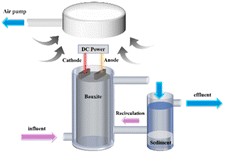
A laboratory-scale IE–BA fluoride removal system, as depicted in Fig. 1, was established. The experimental setup consisted of a cylindrical acrylic reactor with an open top, height of 200 mm and inner diameter of 80 mm, used for batch reaction tests. The empty bed volume of the reactor was 1004 mL. Two aluminum electrode plates, each with a length of 15.0 cm and a width of 5.6 cm, were employed as the anode and cathode. Aluminum ore with a diameter of 2–5 mm was filled between and around the electrode plates, with the upper edge of the electrodes submerged in the packed ore particles. When the reactor was filled with the catalyst, the effective volume of the solution in the reactor was 270 mL. The current density was calculated as the ratio of the current to the total surface area of the anode (84 cm2). The power supply operated in constant current mode and was provided by a DC power source (MAISHENG, MS-155D, China). The solution feed was driven by a peristaltic pump (Kamoer, DIPUMP 550, China).The experimental procedure
First, an Energy-Dispersive Spectroscopy (EDS) analysis was conducted on the natural bauxite ore to determine its chemical and mineral composition. Subsequently, the fluorine removal potential of IE–BA was investigated under the conditions of a thickness of 2.0 cm between the electrode plates, a current density of 0.3 mA cm−2, and an initial pH of 8.0. Furthermore, the effect of different initial pH levels on the defluorination performance was studied by introducing simulated water containing 10.0 mg L−1 F− into IE–BA at a current density of 0.2 mA cm−2, with pH values ranging from 6.0 to 10.0 pH adjustment was achieved using 0.1 M NaOH and 0.1 M H2SO4.The influence of different forms of Al3+ under different pH conditions was simulated using Visual MINTEQ 3.1 to help explain the experimental results. Subsequently, the effect of different current densities (0, 0.1, 0.2, 0.3 mA cm−2) on fluoride removal was investigated in simulated water containing 10.0 mg L−1 F− under the optimal pH conditions. Moreover, the effect of different thicknesses of inter-electrode mineral layers (0.5, 1.0, 1.5, 2.0 cm) on fluoride removal was studied under the optimal pH and current density conditions. Batch experiments were conducted to determine the optimal operating conditions, and the IE–BA's fluoride removal efficiency was systematically investigated under varying initial fluoride concentrations (10, 20, 30, 40, and 50 mg L−1) to assess its resistance to initial concentration fluctuations. A continuous 72 hours run test was employed to evaluate the long-term performance of the IE–BA system in terms of fluoride removal. After the experimental phase, a Scanning Electron Microscopy (SEM) analysis was conducted on the minerals within the system, and a comprehensive examination using SEM, EDS, and Fourier Transform Infrared Spectroscopy (FTIR) was performed on the flocs recovered from the water. This rigorous analysis aimed to elucidate the underlying mechanism of fluoride removal by the IE–BA system.
The electrodes were polished using 400-grit sandpaper, degreased with ethanol, and rinsed with deionized water prior to each experiment. The bauxite was washed three times with distilled water and then cleaned in an ultrasonic cleaner for 10 minutes before being naturally dried and placed between the electrodes and around the electrodes. A 1 ml sample was taken from the filtered liquid through a 0.45 μm filter membrane for analysis. After the experiment, the minerals between the electrodes and the sludge in the liquid were collected and subjected to identification and analysis. The entire experimental procedure was conducted within a fume hood for safety and controlled conditions.
Analsyes and calculations
High-resolution scanning electron microscopy (FEI, Quanta 650FEG) was employed to analyze the surface morphology and elemental composition of minerals and sludge. X-ray fluorescence spectroscopy (XRF, ARL Perform) was used, and Fourier-transform infrared spectroscopy (Thermo FTIR, Nicolet 6700) was performed to obtain the infrared spectra of the generated sludge within the wavenumber range of 500–4000 cm−1. The fluoride concentration was measured using a fluoride ion concentration meter (Shanghai Sanxin WS100).The removal efficiency of F− was calculated using eqn (1).
 | (1) |
In the equation, r represents the removal efficiency of F−, c1 denotes the residual concentration of F− in the solution (mg L−1), and c0 represents the initial concentration of F− in the solution (mg L−1).
Results and discussion
Characteristics of raw bauxite material
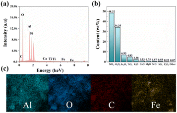
The crystal structure and chemical composition of the original bauxite ore were determined using EDS and XRF, as shown in Fig. 2. Fig. 2a reveals the presence of elements, such as Al, Fe, Ti, and S in the bauxite ore. Furthermore, Fig. 2b displays the content of Al2O3, SiO2, Fe2O3, TiO2, K2O, CaO, MgO, SrO, SO3, P2O5, and other constituents, which account for 48.32%, 34.35%, 6.93%, 4.83%, 2.38%, 1.03%, 0.75%, 0.57%, 0.55%, 0.23%, and 0.07%, respectively. Additionally, the distribution of elements such as Al and Fe throughout the mineral is uniform (Fig. 2c). These results indicate that Al2O3 and SiO2 are the main substances in bauxite ore and can serve as an IE–BA alumina source.Investigation into the defluorination potential of IE–BA
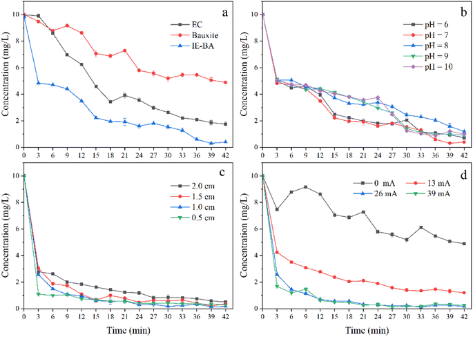
To investigate the defluorination efficiency of IE–BA, a column reactor was first constructed, and the removal effect of fluoride was explored on a laboratory scale (Fig. 3a). Simulated water containing 10 mg L−1 of fluoride and an initial pH of 8.0 was used. The results demonstrated that, under the conditions of a current controlled at 39 mA and a plate spacing of 2.0 cm without the addition of bauxite, the removal efficiency reached 80.5% with a residual concentration of 1.94 mg L−1. When bauxite was added, with the current controlled at 0 mA, the removal efficiency was 51.1% with a residual concentration of 4.88 mg L−1. Moreover, with a current control of 39 mA, the removal efficiency significantly increased to 93.0%, accompanied by a notably lower residual concentration of 0.70 mg L−1. These findings indicate the promising defluorination potential of IE–BA.During the operation of IE–BA, the generation of Fe ions was detected in the solution. This is attributed to the acid dissolution of the electrochemical system, which causes the mineral to release Fe. Previous studies have indicated that the presence of Fe can enhance the defluorination efficiency, and fluoride ions can also increase the removal rate of iron.25 This could also be one of the factors contributing to the higher defluorination efficiency achieved by IE–BA.
Influence factors of defluorination efficiency in IE–BA
Initially, the concentration of fluoride ions in the water rapidly decreased, followed by a slower decline towards the end of the electrochemical process. This phenomenon can be attributed to the initially high mass transfer rate, as numerous available vacant sites exist on the floc responsible for fluoride adsorption.15 This removal kinetics may be associated with the promotion of water oxidation.27,28 Interestingly, there is a phenomenon of a pronounced second decrease in residual F− levels in water. Unlike the initial occurrence, this could be attributed to the accumulation of alkalinity, resulting in a morphological change of Al and the generation of more F− colloid particles with a positive charge, favorable for anion adsorption.29 It is evident that this phenomenon occurred at the 9th minute when pH reached 6.0 and 7.0. However, this phenomenon appeared after 24 minutes under the conditions of pH 8.0 and 9.0, but did not occur at pH 10.0. It is favorable for the IE–BA system to produce more metal ions when the initial pH is weakly acidic or neutral, but an excessively alkaline environment is not conducive to the formation of colloidal Al3+ for the removal of F− from water.30 In summary, under the initial pH condition of 7.0, there was a significant decrease in the concentration of F− during the removal process, and the final concentration was also lower than the residual concentrations under other pH conditions. Therefore, a pH of 7.0 was chosen as the initial condition for further experiments investigating other factors.
Thickness of the interelectrode mineral layer
The thickness of the interelectrode mineral layer is an important operational parameter in electrochemical reactions, as it significantly affects the electrochemical removal of pollutants. The influence of different thicknesses of the interelectrode mineral layer (0.5 cm, 1.0 cm, 1.5 cm, 2.0 cm) on fluoride removal efficiency was investigated under the conditions of initial pH of 7.0, fluoride concentration of 10.0 mg L−1, and current density of 0.2 mA cm−2, as shown in Fig. 3c. The residual fluoride concentration in water initially decreased and then increased with an increase in the thickness of the interelectrode mineral layer. The best removal efficiency for fluoride was observed with a thickness of 1.0 cm, after 42 minutes of reaction, the residual fluoride concentration in water was 0.13 mg L−1, corresponding to a removal rate of 98.7%. When the thickness of the interelectrode mineral layer was 0.5 cm and 1.5 cm, the fluoride removal efficiency was similar, with removal rates exceeding 95.0% (96.8% and 97.0% respectively), and the residual fluoride concentrations in water were 0.31 mg L−1 and 0.29 mg L−1 respectively. A slight decrease in the fluoride removal efficiency was observed when the thickness of the interelectrode mineral layer was 2.0 cm, with a removal rate of 94.4% and a residual fluoride concentration of 0.56 mg L−1.One possible reason for this phenomenon could be the inadequate thickness of the interplate mineral layer (0.5 cm), which hampers the diffusion of cations. A suitable thickness of the interplate mineral layer would enhance the hydrolysis of metal cations, resulting in the formation of stable flocs that adsorb fluoride ions, thereby decreasing the residual fluoride concentration in water.29 However, excessive thickness of the mineral layer (1.5 cm, 2.0 cm) diminishes the interaction between fluoride ions and hydroxyl polymers, leading to decreased mass transfer efficiency and consequently impacting defluoridation effectiveness.31 Furthermore, an increase in the distance between electrodes promotes the formation of passive anodic films, thereby elevating ohmic resistance and impeding floc formation.32 Some studies have also suggested that a reduction in local concentration and electrostatic attraction leads to lower removal rates.29
Current density
The F− solution with a concentration of 10 mg L−1 was treated using the IE–BA process with an inter-electrode mine layer thickness of 1.0 cm and different current densities (0, 0.1, 0.2, 0.3 mA cm−2). The results are shown in Fig. 3d. Under no current condition (0 mA), the residual F− concentration was 4.88 mg L−1 with a removal rate of 51.2%. When the current was increased to 13 mA (0.1 mA cm−2), the residual F− concentration decreased to 1.19 mg L−1 with an improved removal rate of 88.1%. With the current of 26 mA (0.2 mA cm−2), the residual F− concentration further decreased to 0.16 mg L−1, demonstrating a removal rate of 98.4%. Interestingly, when the current was increased from 26 mA (0.2 mA cm−2) to 39 mA (0.3 mA cm−2), the residual F− concentration increased to 0.24 mg L−1 and the removal rate decreased to 97.6%, which represented a 0.8% decline compared to the previous condition.With an increase in the applied current intensity, the concentration of dissolved metal ions in water also increases. Consequently, a greater amount of flocs can remove F− from the water.17 However, this process is limited by the current density. Exceeding this value results in an excessive dosage of coagulant and can cause the rupture of flocs due to gas bubbling, ultimately reducing the removal efficiency of pollutants.33 Excessive metal ions can also impact water quality and human health, as well as lead to unnecessary energy consumption, making it economically unfeasible for the removal of F from water through IE–BA. Therefore, a current of 26 mA (0.2 mA cm−2) was chosen as the optimal operational condition.
Evaluation of operational effectiveness
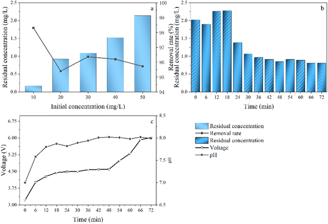
In a batch experiment, the nearly optimal conditions for defluorination using the IE–BA system were investigated. This finding will more easily meet the demand for resource recovery as a household device and promote the application of the IE–BA system in sparsely populated regions. In natural water bodies, the concentration of fluoride (F−) is not fixed. To assess the capability of the IE–BA system to resist variations in water quality, simulated water containing different concentrations of F− (10 mg L−1, 20 mg L−1, 30 mg L−1, 40 mg L−1, 50 mg L−1) was introduced into the system, and the defluorination effectiveness was determined, as shown in Fig. 4a. In batch experiments, the defluorination efficiency was found to consistently exceed 95.2% across different concentrations.To validate the system's feasibility for practical applications, a continuous operation test was conducted by introducing a solution containing 10 mg L−1 of F− over a duration of 72 hours (Fig. 4b). The system demonstrated effective removal, with a final concentration of 9.19 mg L−1 and a residual concentration of 0.81 mg L−1, resulting in a removal rate of 91.9%. Throughout the operation, the treated water maintained a weak alkaline pH. However, over time, the voltage increased by 2.0 V, leading to a slight increase in energy consumption (Fig. 4c).
Exploring the characteristics of minerals and sludge and the mechanism of fluoride removal in the IE–BA system.
The characterization of the minerals before and after the reaction, as well as the produced sludge, was conducted to gain a deeper understanding of their characteristics, assess their further utilization, and validate the hypothesized fluoride removal mechanism in the IE–BA system. The surface morphology of the generated sludge was revealed through SEM images (Fig. 5c and d), which displayed irregular agglomerates of particles. In addition, the EDS analysis shown in Fig. 5b confirmed the presence of fluorine, aluminum, iron, and other elements in the sludge. The FTIR analysis of sludge, performed in the wavenumber range of 400–4000 (Fig. 5a), revealed peaks at 3470 and 1638, which are likely attributed to the presence of O–H stretching.34,35 Peaks at 1010 and 1526 represent the presence of O–H bending and Al–O bond stretching, respectively.33,36 A peak at 610 indicates the presence of Al–F–Al bond,15 while the peak at 1638 is attributed to the presence of O–H.37 A comparison of the SEM images of the minerals before and after the reaction reveals a layered structure on the surface of the raw ore (Fig. 5e and d). In contrast, the surface of the reacted bauxite exhibits a porous structure (Fig. 5g and h), which may be attributed to the electrochemical reaction-generated H+. Additionally, the surface exhibits agglomerated substances resembling flocs.
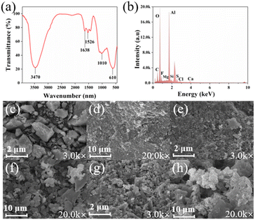 | ||
| Fig. 5 Characterization characteristics analysis of sludge (a) FTIR plot, (b) EDS plot. SEM images (c) and (d) of natural bauxite, (e) and (f) of reacted bauxite, and (g) and (h) of sludge. | ||
These characterizations provide valuable and comprehensive information regarding the microstructural changes before and after mineral reactions, as well as the chemical composition of the sludge. This allows us to elucidate the mechanism of fluoride removal through the IE–BA process. In conjunction with the use of Al as an electrode material in electrochemical reactions, the IE–BA system can encompass the following aspects:11,38,39
Anode:
| 2H2O → 4H+ + O2↑ + 4e− | (2) |
| 2Al(s) → 2Al(aq)3+ + 6e− | (3) |
Reaction in bauxite solution:
| Al2O3(s) + 6H+ → 2Al(aq)3+ + 3H2O | (4) |
Cathode:
| 10H2O + 10e− → 10OH− + 5H2↑ | (5) |
Reaction in aqueous solution:
| H+ + OH− → H2O | (6) |
| Al(aq)3+ + OH− → Al(OH)2+ | (7) |
| Al(OH)2+ + OH− → Al(OH)2+ | (8) |
| Al(OH)2+ + OH− → Al(OH)3 | (9) |
| Al(OH)3 + OH− → Al(OH)4− | (10) |
| nAl(aq)3+ + mOH− + (3n − m)F− → AlnOHmF(3n−m)(s) | (11) |
The proposed mechanism for this phenomenon, as illustrated in Fig. 6, is typically based on the electrolysis of H+ and OH− in a typical electrochemical system generated at the anode and cathode, respectively (eqn (2) and (5)), and their recombination to maintain the system's pH (eqn (5)). As a result, the pH of the electrolyte solution remains relatively unchanged. However, in the IE–BA process, a significant portion of H+ ions are consumed by the bauxite particles, while Al3+ is released into the solution from the bauxite (eqn (4)). Additionally, Al (s) also releases Al3+ through electrochemical reactions (eqn (3)). As the electrochemical reaction progresses, the generation of H+ and OH− ions becomes limited, leading to the accumulation of OH− ions in the solution. The generation of Al3+ and OH− ions triggers the formation of numerous monomeric and polymeric hydroxy metal compounds (eqn (7)–(10)), such as Al(OH)2+, Al2(OH)24+, Al(OH)4− and Al(OH)2+,40,41 and higher polymeric species like Al6(OH)153+, Al7(OH)174+, Al8(OH)204+, Al13(OH)345+, and Al8O4(OH)247+.
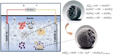 | ||
| Fig. 6 Schematic diagram depicting the acid hydrolysis of bauxite and the fluoride removal mechanism in the IE–BA system. | ||
According to the kinetics of complex precipitation, these substances further transform into amorphous Al(OH)3(s).42,43 This complex, Al(OH)3(s), is believed to have the capacity to adsorb fluoride.44 Additionally, these newly formed metal hydroxide compounds possess strong affinity for adsorbing pollutant ions, accompanied by a large surface area. Through processes such as flocculation, adsorption, sweep flocculation, and co-precipitation, they eventually settle as sludge at the bottom of the reactor (eqn (11)).30,45,46
Conclusions
In this study, the innovative combination of electrochemical acid-base zone and the characteristics of alumina dissolution in acid and the formation of metal ions hydroxide floc in alkaline solution were adopted. A new defluorination system, named IE–BA, was developed by cleverly integrating inexpensive alumina with an electrochemical system. The reactor utilizes industrial aluminum electrodes in conjunction with abundant and low-cost natural alumina to remove F− from water. The analysis of the physicochemical properties of alumina confirmed its feasibility as an aluminum source for the IE–BA system. The IE–BA system demonstrates strong resistance to pH interference and can improve the fluoride removal efficiency by appropriately increasing the current density under a suitable ore layer thickness. By optimizing the experimental conditions, it was found that at an initial pH of 7.0, an ore layer thickness of 1.0 cm, and a current density of 0.2 mA cm−2 (26 mA), the removal rate of F− can reach 98.4%. The defluorination rate of the IE–BA system can exceed 95.2% at different initial concentrations. After continuous operation for 72 hours, the defluorination rate remained at 91.9%. The effluent pH was weakly alkaline (pH = 7.99), and the voltage increased by 2.0 V compared to the initial state during system operation. These results demonstrate that the IE–BA system has the advantages of adjustable flexibility, adaptability, and strong load resistance. Thus, it holds the potential for automation and remote control and can be applied to remove F− from water in decentralized households, military facilities, and remote areas that are not connected to the municipal water supply network.Author contributions
X. X. Meng: conceptualization, methodology, writing—original draft preparation, writing—review and editing; J. F. Li: validation, supervision, project administration, funding acquisition, writing—review and editing; W. Y. Qu and W. H. Wang: validation, data curation; X. T. Feng and J. K. Wang: software, data curation, visualization, investigation.Conflicts of interest
The authors declare that they have no competing financial interests or personal relationships that may have influenced the work reported in this study.Acknowledgements
Financial support from the National Natural Science Foundation of China (52260002, 52300214), the Youth Innovation and Cultivation Talent Project of Shihezi University (CXFZ202201, CXPY202201), the Annual Youth Doctoral Program of Xinjiang Uyghur Autonomous Region ‘Tianchi Elite’ Introduction Plan (CZ002302, CZ002305), High Level Talent Research Launch Project of Shihezi University (RCZK202321, RCZK202002) are gratefully acknowledged.Notes and references
- S. Ayoob and A. K. Gupta, Crit. Rev. Environ. Sci. Technol., 2006, 36, 433–487 CrossRef CAS.
- A. Chowdhury, M. K. Adak, A. Mukherjee, P. Dhak, J. Khatun and D. Dhak, J. Hydrol., 2019, 574, 333–359 CrossRef CAS.
- T. L. Tan, P. A. P. Krusnamurthy, H. Nakajima and S. A. Rashid, RSC Adv., 2020, 10, 18740–18752 RSC.
- Y. Gan, X. Wang, L. Zhang, B. Wu, G. Zhang and S. Zhang, Chemosphere, 2019, 218, 860–868 CrossRef CAS PubMed.
- M. Mohapatra, S. Anand, B. K. Mishra, D. E. Giles and P. Singh, J. Environ. Manage., 2009, 91, 67–77 CrossRef CAS PubMed.
- S. Bibi, A. Farooqi, K. Hussain and N. Haider, J. Cleaner Prod., 2015, 87, 882–896 CrossRef CAS.
- M. M. Damtie, Y. C. Woo, B. Kim, R. H. Hailemariam, K.-D. Park, H. K. Shon, C. Park and J.-S. Choi, J. Environ. Manage., 2019, 251, 109524 CrossRef CAS PubMed.
- S. Meenakshi and N. Viswanathan, J. Colloid Interface Sci., 2007, 308, 438–450 CrossRef CAS PubMed.
- F. D. Belkada, O. Kitous, N. Drouiche, S. Aoudj, O. Bouchelaghem, N. Abdi, H. Grib and N. Mameri, Sep. Purif. Technol., 2018, 204, 108–115 CrossRef.
- C. Y. Hu, S. L. Lo, W. H. Kuan and Y. D. Lee, Water Res., 2005, 39, 895–901 CrossRef CAS PubMed.
- M. Kobya, U. Gebologlu, F. Ulu, S. Oncel and E. Demirbas, Electrochim. Acta, 2011, 56, 5060–5070 CrossRef CAS.
- W. Zhang, Y. Mao and Y. Lu, PLoS One, 2021, 16, e0244711 CrossRef CAS PubMed.
- E. Lacasa, P. Cañizares, C. Sáez, F. J. Fernández and M. A. Rodrigo, Sep. Purif. Technol., 2011, 79, 15–19 CrossRef CAS.
- X. Meng, P. Zeng, S. Lin, M. Wu, L. Yang, H. Bao, J. Kang, H. Han, C. Zhang and W. Sun, J. Cleaner Prod., 2023, 416, 109524 Search PubMed.
- M. Changmai, M. Pasawan and M. K. Purkait, Sep. Purif. Technol., 2018, 206, 140–148 CrossRef CAS.
- M. Molano-Mendoza, D. Donneys-Victoria, N. Marriaga-Cabrales, M. A. Mueses, G. Li Puma and F. Machuca-Martínez, MethodsX, 2018, 5, 915–923 CrossRef PubMed.
- M. A. Sandoval, R. Fuentes, A. Thiam and R. Salazar, Sci. Total Environ., 2021, 753, 142108 CrossRef CAS PubMed.
- X. Zhao, B. Zhang, H. Liu and J. Qu, J. Hazard. Mater., 2010, 184, 472–476 CrossRef CAS PubMed.
- M. A. Shehzad, A. Yasmin, X. Ge, Z. Ge, K. Zhang, X. Liang, J. Zhang, G. Li, X. Xiao, B. Jiang, L. Wu and T. Xu, Nat. Commun., 2021, 12, 9 CrossRef CAS PubMed.
- N. Sikdar, J. R. C. Junqueira, S. Dieckhöfer, T. Quast, M. Braun, Y. Song, H. B. Aiyappa, S. Seisel, J. Weidner, D. Öhl, C. Andronescu and W. Schuhmann, Angew. Chem., Int. Ed., 2021, 60, 23427–23434 CrossRef CAS PubMed.
- S. I. Alhassan, Y. J. He, L. Huang, B. C. Wu, L. J. Yan, H. Y. Deng and H. Y. Wang, J. Environ. Chem. Eng., 2020, 8, 104532 CrossRef CAS.
- K. Cherukumilli, T. Maurer, J. N. Hohman, Y. Mehta and A. J. Gadgil, Environ. Sci. Technol., 2018, 52, 4711–4718 CrossRef CAS PubMed.
- A. Salifu, B. Petrusevski, E. S. Mwampashi, I. A. Pazi, K. Ghebremichael, R. Buamah, C. Aubry, G. L. Amy and M. D. Kenedy, J. Environ. Manage., 2016, 181, 108–117 CrossRef CAS PubMed.
- S. I. Alhassan, H. Wang, Y. He, L. Yan, Y. Jiang, B. Wu, T. Wang, H. Gang, L. Huang, L. Jin and Y. Chen, J. Hazard. Mater., 2022, 430, 128401 CrossRef CAS PubMed.
- D. Das and B. K. Nandi, J. Environ. Chem. Eng., 2020, 8, 103643 CrossRef CAS.
- X. Li, P. Zhang, H. Huang, X. Hu, Y. Zhou and F. Yan, RSC Adv., 2019, 9, 39055–39063 RSC.
- P. Ratna Kumar, S. Chaudhari, K. C. Khilar and S. P. Mahajan, Chemosphere, 2004, 55, 1245–1252 CrossRef CAS PubMed.
- C. Ucar, M. B. Baskan and A. Pala, Korean J. Chem. Eng., 2013, 30, 1889–1895 CrossRef CAS.
- L. S. Thakur and P. Mondal, J. Environ. Manage., 2017, 190, 102–112 CrossRef CAS PubMed.
- S. S. Moersidik, R. Nugroho, M. Handayani, Kamilawati and M. A. Pratama, Heliyon, 2020, 6, e03319 CrossRef PubMed.
- L. F. Castañeda, O. Coreño, G. Carreño and J. L. Nava, Chem. Eng. Process., 2023, 190, 109434 CrossRef.
- K. S. Hashim, A. Shaw, R. Al Khaddar, M. Ortoneda Pedrola and D. Phipps, J. Environ. Manage., 2017, 197, 80–88 CrossRef CAS PubMed.
- M. A. Sandoval, R. Fuentes, J. L. Nava and I. Rodríguez, Sep. Purif. Technol., 2014, 134, 163–170 CrossRef CAS.
- Z.-e.-H. Aftab, W. Aslam, A. Aftab, A. N. Shah, A. Akhter, U. Fakhar, I. Siddiqui, W. Ahmed, F. Majid, J. Wróbel, M. D. Ali, M. Aftab, M. A. A. Ahmed, H. M. kalaji, A. Abbas and U. Khalid, Sci. Rep., 2022, 12, 8561 CrossRef CAS PubMed.
- S. Huang, L. Zhou, M.-C. Li, Q. Wu and D. Zhou, Materials, 2017, 10, 80 CrossRef PubMed.
- M. Amina, N. M. Al Musayeib, N. A. Alarfaj, M. F. El-Tohamy, G. A. Al-Hamoud and H. M. Al-yousef, Pharmaceutics, 2021, 13, 2197 CrossRef CAS PubMed.
- Z. Cai, X. Wang, Z. Zhang, Y. Han, J. Luo, M. Huang, B. Zhang and Y. Hou, RSC Adv., 2019, 9, 13623–13630 RSC.
- D. Ghosh, H. Solanki and M. K. Purkait, J. Hazard. Mater., 2008, 155, 135–143 CrossRef CAS PubMed.
- D. Das and B. K. Nandi, J. Environ. Chem. Eng., 2019, 7, 103116 CrossRef CAS.
- E. Bazrafshan, L. Mohammadi, A. Ansari-Moghaddam and A. H. Mahvi, J. Environ. Health Sci. Eng., 2015, 13, 1–16 CrossRef PubMed.
- D. Ghosh, C. R. Medhi and M. K. Purkait, Chemosphere, 2008, 73, 1393–1400 CrossRef CAS PubMed.
- M. Behbahani, M. R. A. Moghaddam and M. Arami, Desalination, 2011, 271, 209–218 CrossRef CAS.
- L. Rajic, N. Fallahpour, E. Podlaha and A. Alshawabkeh, Chemosphere, 2016, 147, 98–104 CrossRef CAS PubMed.
- C. Y. Hu, S. L. Lo and W. H. Kuan, Water Res., 2003, 37, 4513–4523 CrossRef CAS PubMed.
- U. Tezcan Un, A. S. Koparal and U. Bakir Ogutveren, Chem. Eng. J., 2013, 223, 110–115 CrossRef CAS.
- M. M. Emamjomeh and M. Sivakumar, J. Environ. Manage., 2009, 90, 1663–1679 CrossRef CAS PubMed.
Footnote |
| † Electronic supplementary information (ESI) available. See DOI: https://doi.org/10.1039/d4ra01359j |
| This journal is © The Royal Society of Chemistry 2024 |

