 Open Access Article
The microstructure and protective properties of electroplating zinc films on NdFeB from a chloride-free nonaqueous bath†
Li Xiaoya,
Ma Yongcun,
Peng Shusen * and
Tian lixi
School of Materials Science and Engineering, Jiangxi Provincial Engineering Research Center for Surface Technology of Aeronautical Materials, Nanchang Hangkong University, Nanchang 330063, China. E-mail: pengshs@nchu.edu.cn
First published on 14th March 2024
Abstract
The traditional aqueous electroplating of zinc film causes significant corrosion of NdFeB during the electroplating process, which is accompanied by hydrogen evolution reactions. In this study, electroplating zinc film is carried out from a chloride-free nonaqueous bath using zinc acetate (Zn(OAc)2) as the main salt, sodium acetate (NaOAc) as the conducting salt, and ethylene glycol (EG) as the solvent. The electrochemical properties of the EG bath with Zn(OAc)2 and NaOAc are characterized by means of cyclic voltammetry (CV) and linear sweep voltammetry (LSV) together with a Hull cell test on brass. The results of the experiment show that the Zn(OAc)2 concentration, current density, and temperature significantly impact the deposition behavior of zinc. Moreover, the open circuit potential (OCP) test and scanning electron microscopy (SEM) results demonstrated that the corrosion of NdFeB in the EG bath containing 0.7 M Zn(OAc)2 and NaOAc is effectively inhibited compared to when using the traditional aqueous zinc plating bath. A dense zinc film with a metallic appearance is successfully deposited on the NdFeB surface from the EG bath containing 0.7 M Zn(OAc)2 and NaOAc at 6 mA cm−2 and 60 °C. Comparative experiments demonstrate that the as-deposited Zn film exhibits superior protective performance and exerts less damage to NdFeB compared to the aqueous electroplating film.
1. Introduction
Permanent magnetic materials are widely utilized in various industries and daily life, including in electric, electronic, and electromechanical devices. Sintered NdFeB is particularly favored as the leading commercial permanent magnet due to its numerous advantages.1 In particular, NdFeB is often used in demanding corrosive environments such as marine and industrial settings involving acids.2,3 However, due to the high reactivity of Nd and Fe and the relatively loose structure of sintered NdFeB, corrosion susceptibility is a significant issue, resulting in premature function failure.4–6 Therefore, protective measures need to be implemented to mitigate corrosion effects on these magnets.7–11 Presently, the primary approach to protecting NdFeB from corrosion involves utilizing various coating materials.12–14 Metal coatings, such as Ni,15–18 Ni–P,19,20 Ni–Cu,21,22 Zn,23–26 are the most popular choices in the industry. So far, aqueous electroplating is still the most widely used method of metal coating deposition,27–30 although physical vapor deposition,31–33 chemical vapor deposition,4 thermal spraying,34 and other technologies have also developed. Unfortunately, NdFeB is prone to corrosion during the aqueous electroplating process due to exposure to the electrolytic bath solution. Furthermore, the unavoidable electrolysis of water during the process introduces hydrogen embrittlement, which can adversely affect the mechanical and magnetic properties of the magnet. Consequently, the use of nonaqueous electrolytes in nonaqueous electroplating has been explored as a potential solution for overcoming these drawbacks.35 A nonaqueous bath can minimize secondary reactions, and high-quality films may be obtained, making it an effective alternative approach.36In the past few decades, the most extensively studied nonaqueous systems used for electroplating include ionic liquids (ILs) and deep eutectic solvents (DESs).37 In the former system, the organic solvent used also acts as an electrolyte, while in the latter one, the hydrogen bond donor (HBD) is mixed with the hydrogen bond acceptor (HBA) (such as quaternary ammonium cation) at an appropriate molar ratio to form a conductive eutectic solution. DESs are currently being considered as potential alternatives to traditional electroplating solutions and have even been implemented at industrial scales in some cases.38,39 However, it is essential to note that high concentrations of chloride ions in chloride-based DES baths can create an aggressive environment for the substrate. Therefore, in future research, it is necessary to investigate the elimination or substitution of choline chloride, especially when dealing with active substrates like NdFeB.40 A recent study by Panzeri et al. successfully electroplated a high-purity zinc film using a chloride-free nonaqueous solution consisting of ethylene glycol, acetate salt, and precursor salt.41 Furthermore, their previous research findings indicate that the resulting film deposits exhibited significantly better corrosion performance than those obtained from a chloride-based DES due to a less aggressive/corrosive environment.
In this study, the primary objective is to develop a chloride-free nonaqueous bath that is both efficient and environmentally friendly for the protection of NdFeB magnets. The composition of the bath is based on a combination of ethylene glycol and acetate salts, which presents a promising alternative to traditional chloride-based solutions. A series of experiments are conducted to determine the optimal parameters for the bath, carefully controlling and analyzing factors such as bath temperature, deposition time, current density, and concentration of acetate salts. Additionally, scanning electron microscopy (SEM), Tafel curves, open circuit potential (OCP), and salt spray testing are carried out to assess the surface morphology and corrosion resistance of zinc films. This chloride-free nonaqueous bath offers a practical and environmentally friendly alternative for NdFeB protection and contributes to advancing sustainable and eco-conscious manufacturing processes.
2. Experimental
2.1. Chemicals
Ethylene glycol, zinc acetate, sodium acetate, and potassium acetate (Shanghai Aladdin Bio-Chem Technology Co., Ltd) are used as received. Where ethylene glycol is the hydrogen-bonding donor, zinc acetate is the hydrogen bond acceptor for zinc electroplating, and sodium acetate is used to improve the conductivity of the electroplating bath. NdFeB rod and plate are provided by Anhui Dadixiong New Materials Co., Ltd.2.2. Electroplating Zn films
The NdFeB and brass rod with a diameter of 1 cm used in the experiment is cut, welded with Cu wire for electrical connections, and installed into the epoxy resin with one active flat surface. Successive grades of abrasive papers up to 1000 grit are employed on electrodes and plates, copiously rinsing with distilled water and anhydrous ethanol, and finally drying under nitrogen flow. The Hull cell test is conducted using a conventional two-electrodes cell with a volume of 273 ml. The cathode is comprised of a brass plate measuring 10 × 6.5 cm. The current is set at 0.5 A dm−2, and the test duration is 10 minutes, with a temperature of 60 °C. In the bath solution, the concentration of zinc acetate is varied at 0.1 M, 0.3 M, 0.5 M, and 0.7 M, while the ratio of conductive salt sodium acetate to zinc acetate is maintained at 1![[thin space (1/6-em)]](https://www.rsc.org/images/entities/char_2009.gif) :
:![[thin space (1/6-em)]](https://www.rsc.org/images/entities/char_2009.gif) 1, and is labeled as 0.1M-EG, 0.3M-EG, 0.5M-EG, and 0.7M-EG bath, respectively. The zinc film is electrodeposited onto NdFeB plates using a galvanostatic method for characterization.
1, and is labeled as 0.1M-EG, 0.3M-EG, 0.5M-EG, and 0.7M-EG bath, respectively. The zinc film is electrodeposited onto NdFeB plates using a galvanostatic method for characterization.
2.3. Electrochemical tests
Electrochemical experiments are conducted using an RST 5200 electrochemical workstation from Zhengzhou Shiruisi Instrument Technology Co., Ltd. The experimental setup consisted of a three-electrode system: a platinum plate (1 × 1 cm) served as the counter electrode, a nonaqueous Ag+/AgCl electrode acted as the reference electrode, and a working electrode. The linear sweep voltammetry test is performed in the 0.7M-EG bath as the temperature varies from 30 °C to 60 °C. The scan range extended from the open circuit potential to the negative direction, with a voltage window of 0 to 4 V and a scanning rate of 0.02 V s−1. Different bath solutions are employed at a constant temperature of 60 °C for cyclic voltammetry testing. The scan started from the open circuit potential and went to −2 V in the negative direction, then returned to the open circuit potential at a scanning rate of 0.001 V s−1. The timing current test involved applying a voltage within the −1.9 to −1.92 V range, with step increases of −0.01 V for one second. Tafel curves are obtained by scanning from −0.02 V to +0.25 V relative to OCP, with a scan rate of 0.0005 V s−1.2.4. Characterization
The surface morphologies of the Zn films are examined using scanning electron microscopy (SEM; FEI Quanta 250 FEG, USA). The chemical composition and elemental mapping of the Zn films are detected using energy-dispersive X-ray (EDX) spectroscopy. The crystal features of the deposited Zn films are characterized using an X-ray diffractometer (XRD; Bruker D8 Advance Davinci, Germany). XPS spectra are collected using an AXIS ULTRA DLD X-ray photoelectron spectrometer with an Al-anode. The binding energies are referenced to the binding energy of the C 1s line, which is set at 285.0 eV. The bonding strength between the zinc film and the NdFeB substrate is tested by using an electronic controlled universal testing machine (PY-880, CN). Using glue as a binder to connect the coating with the tie rod, and the tension is applied until the coating and the NdFeB substrate are completely separated.3. Results and discussion
Using acetate salts implies that the anion species in the solution has a larger ionic radius than the chloride usually found in DESs. Consequently, the low conductivity provided by the anion species must be compensated by increasing the amount of metal precursor salt and potentially by incorporating a supporting electrolyte like sodium acetate and potassium acetate, both of which contain the acetate anion. As noted by Panzeri et al.,41 zinc acetate (Zn(OAc)2) exhibits a solubility of no more than 0.75 M in ethylene glycol (EG) at 30 °C. If the salt is further dissolved, it may form a white precipitate (ZnO). The cyclic voltammetry (CV) of the NaOAc–EG bath without 0.7 M Zn(OAc)2, as depicted in Fig. 1a, does not exhibit a pronounced cathode peak within the electrochemical window of −2 to 0 V. This suggests that there are no notable side cathodic reactions leading to the degradation of NaOAc and EG, indicating high stability of the NaOAc–EG bath. Despite the absence of significant secondary reactions, a small amount of hydrogen is also anticipated at lower overpotentials due to the presence of protons in the solution. Fig. 1a also indicates the onset of zinc electrodeposition (Zn2+ → Zn0) at −1.25 V vs. Ag+/Ag for the 0.7M-EG bath, corresponding to the sudden increase in the cathodic current. The observed linear relationship between cathodic potential and current density indicates that the electroplating processes in the 0.7M-EG bath are under kinetic control. To further investigate, linear sweep voltammetry (LSV) is carried out on the brass electrode in the 0.7M-EG bath at different temperatures with a lower cathodic limit (4 V vs. Ag+/Ag). Fig. 1b illustrates that the current density in the 0.7M-EG bath increases as the bath temperature rises. This behavior is attributed to the higher diffusion rate of ions and the reduced viscosity of EG at higher temperatures, resulting in a higher current density. Notably, understanding this correlation between temperature and current density is crucial for optimizing the performance of these baths.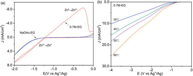 | ||
| Fig. 1 (a) The cyclic voltammetry of the NaOAc–EG and 0.7M-EG bath (1 mV s−1, 60 °C) and (b) linear sweep voltammetry of the 0.7M-EG bath at different temperatures (1 mV s−1). | ||
The current density experiment is conducted in a 267 ml Hull cell, using a current of 0.5 A for electroplating for 10 minutes, with a cathode brass sheet of 10 × 6.5 cm. The distance from the near end of the cathode plate is expressed in X, in cm. The relationship between distance and current density is as follows:
JK = I × (5.10 − 5.24 × log![[thin space (1/6-em)]](https://www.rsc.org/images/entities/char_2009.gif) X), X),
| (1) |
Fig. 2 depicts photographs of the Hull cell experiment conducted in various electroplating baths, in which different concentrations of Zn(OAc)2 and NaOAc at 60 °C. As illustrated in Fig. 2, the substrate is clearly visible at the distal end after electroplating for 10 minutes in the 0.1M-EG bath. This is attributed to the low concentration of zinc salt in the bath, as well as the small current density. The corresponding images reveal distinct variations in appearance after electroplating for 10 minutes in Zn(OAc)2–NaOAc–EG baths with concentrations of 0.3 M, 0.5 M, and 0.7 M, respectively. Notably, metallic zinc films are observed at the distal cathode area, while the zinc films in the proximal cathode region appear black and contain bubbles. Furthermore, the bright area expands with an increase in both zinc salt and conductive salt concentrations.
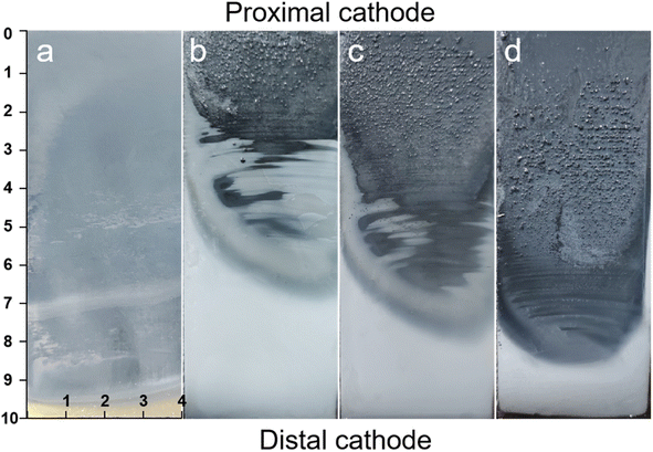 | ||
| Fig. 2 Photo of Hull cell experiment in the different electroplating bath at 60 °C: (a) 0.1M-EG, (b) 0.3M-EG, (c) 0.5M-EG, and (d) 0.7M-EG. | ||
Fig. S1(ESI†) presents the SEM surface morphology of Zn film at different distances from the proximal cathode electroplating from the 0.1M-EG bath. It can be observed that the zinc film is incomplete and consists of dispersed, extremely fine zinc particles. When the concentration of Zn(OAc)2 and NaOAc is increased to 0.3 M, compact films with a hexagonal microstructure are obtained through electrodeposition in the current density range of 1.8–3.3 mA cm−2 (see Fig. S2a†). In Fig. S2b–d,† incomplete zinc films composed of zinc particles are presented, indicating the increased significance of secondary reactions in film morphology when the current density exceeds 3.3 mA cm−2. The SEM morphology differences in the bright area compared to other areas can explain the macroscopic differences in the corresponding regions. As shown in Fig. S3,† a further increase in the Zn(OAc)2 and NaOAc concentration to 0.5 M results in zinc films with different shapes and orientations at different current densities. Compact films like 〈002〉,〈004〉 with multilayer units parallel to the substrate are obtained when the deposition current density is in the range of 1.8–5 mA cm−2. However, zinc films obtained at a deposition current density of 5–10 mA cm−2 exhibit a textured microstructure. Upon comparison (seen Fig. 3), it can be observed that zinc films obtained from the 0.7M-EG bath display a finer nanoscale multi-level structure than those obtained from a 0.5 M bath.
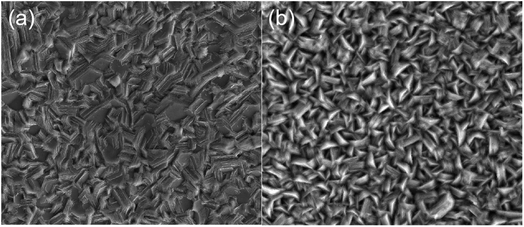 | ||
| Fig. 3 SEM surface morphology of Zn film from the proximal cathode at different distances from the proximal cathode on brass (a) 7–8 cm from the 0.5M-EG bath and (b) 5–6 cm from 0.7M-EG bath. | ||
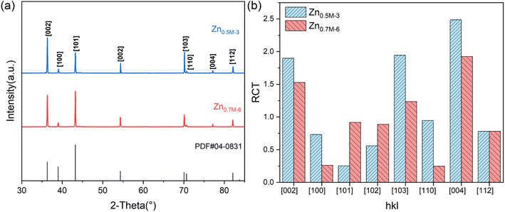
Based on the Hull cell experiment results, two zinc films are obtained through galvanostatic deposition at two different current densities for 30 min: 3 mA cm−2 in the 0.5M-EG bath and 6 mA cm−2 in the 0.7M-EG bath. These films are then analyzed using XRD (see Fig. 4). The diffractograms revealed a significant orientation along the 〈002〉 direction for the former film, while the latter film showed a significant orientation along the 〈101〉 direction. The SEM surface morphology of the former film also shows identifiable hexagonal cells on the basal surface, consistent with a previous report.41 To provide a more precise indication of the microstructural orientation, the relative texture coefficient (RTC) is calculated using the following eqn (2):
 | (2) |
Fig. 5 displays the OCP curves for the NdFeB electrode in an aqueous alkaline zinc plating bath42 and the 0.7M-EG bath. The OCP curves for the NdFeB electrodes in these two baths demonstrate distinct trends. In the aqueous bath, the OCP value sharply increases with time and then tends to stabilize. This observation suggests that the active component of the NdFeB electrode undergoes a corrosion reaction in the aqueous bath. Conversely, in the 0.7M-EG bath, the OCP value decreases rapidly with time and then stabilizes. This behavior may be attributed to the adsorption of EG and Zn2+ complex molecules on the NdFeB electrode, which form a double layer and lead to a change in potential. In order to visually understand the changes that occur during this process, the morphology of the NdFeB magnets is observed through BSE imaging (see Fig. 6). The white areas in the image indicate the Nd-rich phase. The surface of the NdFeB undergoes significant changes after immersing in these two baths for 30 min. In the aqueous bath, corrosion is more severe at the grain boundaries, as the white area nearly disappears, and the main phase grains are accentuated in some regions. Conversely, there is almost no significant corrosion after immersing in the 0.7M-EG bath. Since the current density between the OPC and the initial deposition potential is very small, the electrode is hardly corroded. Considering that these corrosion changes can negatively impact the performance of NdFeB, it is clear that electroplating a zinc film in the EG bath is superior to doing so in the aqueous bath.
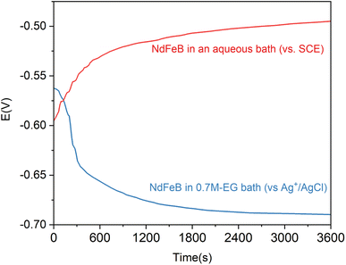 | ||
| Fig. 5 The OCP curves of NdFeB electrodes in an aqueous alkaline zinc plating bath and the 0.7M-EG bath. | ||
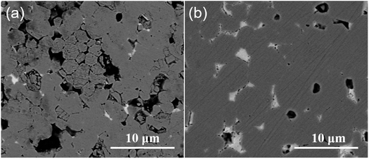 | ||
| Fig. 6 BSE image of NdFeB after immersing in (a) an aqueous alkaline zinc plating bath and (b) the 0.7M-EG bath for 30 min. | ||
Fig. 7 depicts the cyclic voltammetry curves of NdFeB electrodes in different EG baths. The results indicate a significant difference between the initial concentration of 0.1 M and the concentrations of 0.3 M and 0.5 M. However, there is minimal variation between 0.5 M and 0.7 M, likely due to the similarity in the concentrations of free Zn2+ and Na+ in EG, which are close to their saturation points. At a concentration of 0.1 M, only one region of reduction peaks (C2) is observed at approximately −1.89 V. When the concentration increases to 0.3 M, one reduction peaks appear at around −1.84 (C2) V. Subsequently, at a concentration of 0.5 M, two reduction peaks are observed at approximately −1.22 V (C1), −1.84 V (C2) and one oxidation peak at around −0.65 V (A1). Finally, at a concentration of 0.7 M, two reduction peaks are observed at around −0.48 V and −1.25 V (C1). These reduction peaks could be attributed to the redox of the Nd and Fe elements. A1 and C1 are the redox peaks of the matrix, respectively, and C2 and A2 are the oxidation and reduction peaks of Zn2+. In addition, Guilin Xiang et al. also observed the reduction peak of Nd around −1.25 V in the cyclic voltammetry curve of Nd.43 The low conductivity at low concentrations makes the electromigration process very slow, resulting in almost no redox peaks of the substrate, and the peak values of redox peaks are positively correlated with conductivity, and due to the increase of concentration, Zn2+ is no longer controlled by diffusion in the electrodeposition process, resulting in the disappearance of Zn2+ reduction peaks and diffusion plateaus at 0.7 M concentrations.
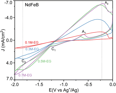 | ||
| Fig. 7 The cyclic voltammetry curves of NdFeB electrodes in the 0.1M-EG, 0.3M-EG, 0.5M-EG, and 0.7M-EG baths (1 mV s−1, 60 °C). | ||
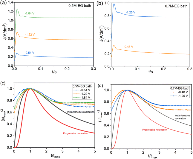
The reduction peak potentials of 0.5 M and 0.7 M are selected for further investigation and experimentation with the Zn reduction processes. The chronoamperometry technique can be utilized to understand the mechanisms of nucleation and growth rates during electrodeposition. According to the literature review,44 the Schariker and Hills models explain the nucleation process, specifically the three-dimensional (3D) instantaneous and asymptotic mechanisms under diffusion control. Eqn (3) and (4) present the mathematical expressions of these models in dimensionless form, which determine the nucleation 3D instantaneous mechanism and asymptotic mechanism, respectively.
In both equations, I is the current density at a particular time t, Im is the maximum current density, and tm is the time obtained at the maximum current peak to perform I.
| Instantaneous: (I/Imax)2 = [1.9542/(t/tmax)]{1 − exp[−1.2564(t/tmax)]}2 | (3) |
| Progressive: (I/Imax)2 = [1.2254/(t/tmax)]{1 − exp[ − 2.3367(t/tmax)2]}2 | (4) |
Fig. 8 depicts a plot of (I/Imax)2 vs. (t/tmax) to illustrate the growth of Zn from the 0.5M-EG and 0.7M-EG bath at 60 °C. The plot shows the theoretical patterns for 3D instantaneous and progressive nucleation. Initially, there is a dramatic increase in current when the overpotential is applied, which can be attributed to double-layer charging. In the next stage, the current reaches its maximum (Im), indicating the formation and growth of Zn particles on the NdFeB substrate. Subsequently, the current decays due to limitations imposed by diffusion processes. A comparison of the nucleation modes in each system, as shown in Fig. 8, reveals that the nucleation mechanism for Zn growth from the 0.7M-EG bath aligns more closely with the expected 3D instantaneous nucleation. This finding is consistent with previous research on Zn deposition. Furthermore, the observation of timing current curves at different potentials reveals that an increase in overpotential leads to a corresponding increase in tmax. This indicates inhibition of nucleation, which may be related to the adsorption of EG molecules at high overpotentials.
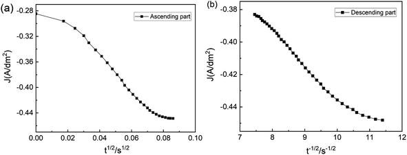
The timing–current curve is processed to validate the experimental data, following Schariker's theory. The J − t1/2 function is used to characterize the rising region of the curve, while the falling region is characterized using the J − t1/2 function. This analysis results in Fig. 9 reveal that the curve does not exhibit a linear correlation and deviates from linearity during the initial and subsequent stages. This finding indicates that the electrodeposition of Zn on NdFeB is governed by a three-dimensional instantaneous nucleation mechanism controlled by electrochemistry and diffusion rather than diffusion alone. The nucleation process plays a crucial role in shaping the structure and morphology of the film, while the growth process after nucleation further influences these characteristics. Specifically, the nucleation and growth processes of electrodeposition significantly impact the final surface morphology of the coating. Electrodeposition can manifest as island-like or layered growth depending on the nucleation processes.
Furthermore, based on the morphology observed during the initial growth stage of the deposited film, the nucleation process can be classified into three modes:43 Volmer–Weber (V–W), Frank–van der Merwe (F–M), and Stranski–Krastanov (S–K). In the V–W mode, deposition initiates with island-like nucleation and gradually progresses to form a complete thin film. The F–M mode occurs when there is lattice matching between the deposited thin film and the substrate. In this mode, metal ions are adsorbed on the electrode surface after reduction, migrate to the active point, and form a continuous spread of base atoms, resulting in single atomic layer growth of the thin film. The S–K mode can be understood as a transitional or intermediate state between the aforementioned deposition modes. The energy difference between the deposition and base atoms in this mode lies between the V–W and S–K modes.
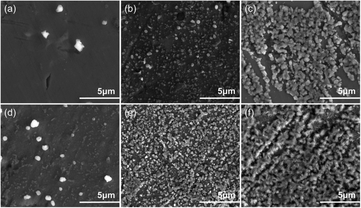
Fig. 10 illustrates the nucleation and growth of zinc films as observed through SEM. Fig. 10a and d demonstrate the formation of a thin zinc layer within 5 s, aligning with the pattern of instantaneous nucleation. After 15 s, the surface is nearly entirely covered, indicating that nucleation and growth are considerably faster in the 0.7M-EG bath than in the 0.5M-EG one. This rapid growth can be attributed to the high concentration and current density, resulting in a higher diffusion coefficient. After 60 seconds, Fig. 10c and f show a specific crystal plane orientation, with the growth in the 0.7 M bath appearing denser and more uniform, showcasing complete coverage. Notably, the EDS of the Zn deposits revealed the presence of zinc and some oxides (see Fig. S5†). These oxides may have resulted from the oxidation of zinc or the substrate after the deposition process due to exposure to air. The SEM images at various time points suggest that the nucleation and growth observed here follow the F–M growth mode.
Fig. 11 illustrates the cross-section morphology and EDS maps of the deposited zinc films on NdFeB, which are obtained through 30 minutes of electroplating from the 0.7M-EG at 6 mA cm−2 (Zn0.7M-6) and from the 0.5M-EG bath at 3 mA cm−2 (Zn0.5M-3). As shown corresponding images in Fig. 11, the deposited Zn0.5M-3 film on NdFeB is characterized by multiple holes, posing a challenge to its corrosion resistance. Furthermore, a small amount of Fe within the film is discernible, along with the existence of Fe in the NdFeB matrix. It can be inferred that the newly reduced Zn displaces the Fe element within the matrix during the initial nucleation stage. This inference aligns with the findings from previous cyclic voltammetry tests. The initial crystal nucleus experiences continuous generation and dissolution due to the displacement effect, forming two closely positioned reduction peaks during the negative scanning process. Encouragingly, the deposited Zn0.7M-6 film exhibits higher density and uniformity. It is worth noting that the adhesion of the zinc film, which is deposited from the EG bath, on NdFeB is significantly higher compared to the film deposited from the aqueous bath. Specifically, the Zn0.7M-6 film on NdFeB demonstrates an average bonding strength of approximately 18.5 MPa, while the zinc film deposited from the aqueous solution bath only achieves an average bonding strength of 11.2 MPa.
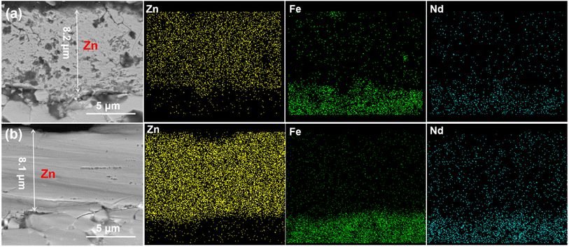 | ||
| Fig. 11 The cross-section and EDS spectra of the zinc coating (a) Zn0.5M-3 (from the 0.5M-EG bath at 2 mA cm−2, 60 min, 60 °C) and (b) Zn0.7M-6 (from the 0.7M-EG bath at 6 mA cm−2, 30 min, 60 °C). | ||
Fig. 12 shows the OCP curves of these as-prepared two Zn films on NdFeB in 3.5 wt% NaCl solution. It can be observed that the OCP value of Zn0.7M-6 is consistently higher than that of Zn0.5M-3. Analyzing the OCP curve of Zn0.7M-6, it is seen that the potential initially drops from −1.01 V to −1.0 V over the first 20 min. This drop may be attributed to the destruction of the oxide film on the surface of the Zn film. As the immersion time reaches 50 min, the potential moves positively to −1.04 V, indicating the formation of corrosion products such as hydroxides. Subsequently, the potential drops and then plateaus as the corrosion products transform into more stable insoluble chlorides. Comparison between Zn0.7M-6 and Zn0.5M-3 reveals a lower OCP value for Zn0.5M-3. The potential value of Zn0.5M-3 decreases from −1.05 V to −1.07 V during the initial stage of oxide film dissolution. This difference in potential can be attributed to numerous holes and gaps in the structure, as suggested by the cross-sectional SEM. These structural defects make it easier for corrosion products to dislodge, rendering them ineffective in hindering further corrosion.
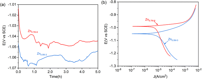 | ||
| Fig. 12 (a) OCP curves and (b) Tafel curves of the Zn0.5M-3 and Zn0.7M-6 covered NdFeB in 3.5 wt% NaCl solution. | ||
Tafel curves are also carried out to compare the corrosion behavior of these as-prepared two zinc films (see Fig. 13). The Tafel curve gives the corrosion potential value of −1.04 V for Zn0.5M-3 film, which is lower than that of −0.99 V for Zn0.7M-6 film, in line with the OCP test. The corrosion current densities are Icorr = 5.8 × 10⁻⁶ A cm−2 and Icorr = 5.03 × 10⁻⁶ A cm−2, respectively. The difference in corrosion potential between these two films may be due to the differences in surface microstructure, crystal orientation, and grain size. Moreover, the current density of the anode and cathode branches of the Zn0.7M-6 film is slightly lower than that of Zn0.5M-3 film, which may be attributed to the more compact film on the surface of Zn0.7M-6 film. As a result, the corrosive medium cannot enter the inside of the zinc coating. Secondly, due to its dense structure, the corrosion products on the surface are not easy to fall off, which can effectively hinder the corrosion process.
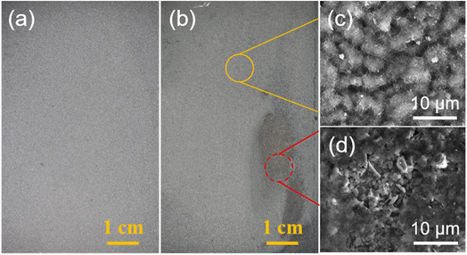 | ||
| Fig. 13 Photos of NdFeB with (a) Zn0.7M-6 and (b) Zn0.5M-3 after immersion in a 3.5 wt% NaCl solution for 12 hours. (c) and (d) SEM surface morphology in corresponding regions of (b). | ||
Fig. 13 shows the optical and SEM images of NdFeB covered with Zn0.7M-6 and Zn0.5M-3 film after immersion in a 3.5 wt% NaCl solution for 12 hours. As shown in the figure, the Zn0.7M-6 film on NdFeB maintains a distinct metallic color, albeit slightly darker, implying its superior integrity and absence of discernible defects. Conversely, the Zn0.5M-3 immersion exhibits evident red rust after the same time period, indicating that the corrosive medium has breached the Zn film and caused corrosion of the NdFeB substrate.
4. Conclusion
The high-quality zinc film is successfully electroplated on NdFeB from a chloride-free nonaqueous bath using Zn(OAc)2 as the primary salt, NaOAc as the conductive salt, and EG as the solvent. In comparison to the traditional alkaline plating bath, the corrosion caused by this electroplating bath on NdFeB is virtually negligible. The results of the experiments demonstrate that the concentration of Zn(OAc)2, current density, and temperature have a significant impact on the deposition behavior of zinc. The optimal conditions for Zn deposition are as follows: an EG bath consisting of 0.7 M Zn(OAc)2 and NaOAc, at a temperature of 60 °C, with a current density of 6 mA dm−2. The optimized zinc film exhibits a distinct metallic appearance, and the SEM cross-section reveals that the film is dense and exhibits good adhesion to NdFeB.Conflicts of interest
There are no conflicts to declare.Acknowledgements
The authors gratefully acknowledge the financial support from the National Natural Science Foundation of China (No. 51861028) and Jiangxi Provincial Natural Science Foundation of China (20224BAB204018).References
- O. Gutfleisch, M. A. Willard, E. Brück, C. H. Chen, S. G. Sankar and J. P. Liu, Magnetic Materials and Devices for the 21st Century: Stronger, Lighter, and More Energy Efficient, Adv. Mater., 2011, 23(7), 821–842, DOI:10.1002/adma.201002180.
- P. Cavallotti, B. Bozzini, R. Cecchini, G. F. Bava, H. A. Davies and C. Hoggarth, Corrosion and protection of NdFeB type magnets, J. Magn. Magn. Mater., 1992, 104, 1216–1218, DOI:10.1016/0304-8853(92)90555-3.
- S. A. Attanasio and R. M. Latanision, Corrosion of rapidly solidified neodymium-iron-boron (NdFeB) permanent magnets and protection via sacrificial zinc coatings, J. Mater. Sci. Eng. A, 1995, 198(1), 25–34, DOI:10.1016/0921-5093(95)80055-Y.
- H. H. Man, H. C. Man and L. K. Leung, Corrosion protection of NdFeB magnets by surface coatings - Part I: Salt spray test, J. Magn. Magn. Mater., 1996, 152(1), 40–46, DOI:10.1016/0304-8853(95)00453-X.
- H. H. Man, H. C. Man and L. K. Leung, Corrosion protection of NdFeB magnets by surface coatings - Part 2: Electrochemical behaviour in various solutions, J. Magn. Magn. Mater., 1996, 152(1), 47–53, DOI:10.1016/0304-8853(95)00454-8.
- S. N. B. Hodgson, C. G. Hoggarth, H. A. Davies and R. A. Buckley, Protection of NdFeB magnets by ultra-thin sol-gel derived films, J. Mater. Process. Technol., 1999, 93, 518–524 CrossRef.
- S. M. Tamborim Takeuchi, D. S. Azambuja, A. M. Saliba-Silva and I. Costa, Corrosion protection of NdFeB magnets by phosphating with tungstate incorporation, Surf. Coat. Technol., 2006, 200(24), 6826–6831, DOI:10.1016/j.surfcoat.2005.10.029.
- S. Yu and L. Chen, Preparation Technology and Performances of Zn-Cr Coating on Sintered NdFeB Permanent Magnet, J. Rare Earths, 2006, 24(2), 223–226, DOI:10.1016/S1002-0721(06)60098-7.
- L. Song, Y. Wang, W. Lin and Q. Liu, Primary investigation of corrosion resistance of Ni-P/TiO2 composite film on sintered NdFeB permanent magnet, Surf. Coat. Technol., 2008, 202(21), 5146–5150, DOI:10.1016/j.surfcoat.2008.05.025.
- Y. Song and Z. Song, Electrodeposited nickel/alumina composite coating on NdFeB permanent magnets, Mater. Corros., 2008, 59, 324–328, DOI:10.1002/maco.200804107.
- H. Zhang, Y. Song and Z. Song, Electrodeposited Ni/Al2O3 Composite Coating on NdFeB Permanent Magnets, Key Eng. Mater., 2008, 373–374, 232–235, DOI:10.4028/www.scientific.net/KEM.373-374.232.
- Q. Feng, Y. Huang, H. Li, J. Y. Yu, C. Y. Wang, Z. Wu, Y. Yao, Y. Hou, W. Li, L. Ma and H. Yu, Elevated corrosion resistance and improved magnetic properties of sintered Nd-Fe-B magnets via the infiltration of DyCr film, J. Alloys Compd., 2023, 940, 168827, DOI:10.1016/j.jallcom.2023.168827.
- J. Y. He, X. F. Liao, X. X. Lan, W. Q. Qiu, H. Y. Yu, J. S. Zhang, W. B. Fan, X. C. Zhong and Z. W. Liu, Annealed Al-Cr coating: A hard anti-corrosion coating with grain boundary modification effect for Nd-Fe-B magnets, J. Alloys Compd., 2021, 870, 159229, DOI:10.1016/j.jallcom.2021.159229.
- R. Cao, L. Q. Zhu, W. P. Li, W. Hu and H. C. Liu, The effect of alumina-silica sols on electrodeposited zinc coatings for sintered NdFeB, J. Alloys Compd., 2017, 726, 95–106, DOI:10.1016/j.jallcom.2017.06.123.
- D. J. Blackwood, B. Balakrisnan, Y. Z. Huang and C. K. Tan, Influence of the chemical composition of the plating solution on the ability of nickel coatings to protect Nd2Fe14B magnets against corrosion, J. Magn. Magn. Mater., 2001, 223(2), 103–111, DOI:10.1016/S0304-8853(00)00716-2.
- E. Isotahdon, E. Huttunen-Saarivirta, V. T. Kuokkala, M. Paju and L. Frisk, Corrosion protection provided by electrolytic nickel and tin coatings for Nd–Fe–B magnets, J. Alloys Compd., 2014, 585, 203–213, DOI:10.1016/j.jallcom.2013.09.135.
- P. J. Zhang, Q. Liu, J. Huang, J. W. Cui, W. Sun, B. S. Li and G. Q. Xu, Phosphate conversion of electroplated Ni coatings on NdFeB magnets improving the anticorrosion property, J. Alloys Compd., 2022, 922, 166206, DOI:10.1016/j.jallcom.2022.166206.
- W. Jiang, L. D. Shen, K. Wang, M. Y. Xu and Z. J. Tian, Study on Ni-Ni(S)-Ni(P) multilayer coating by friction-assisted jet electroplating on sintered NdFeB, J. Alloys Compd., 2019, 787, 1089–1096, DOI:10.1016/j.jallcom.2019.02.102.
- C. B. Ma, F. H. Cao, Z. Zhang and J. Q. Zhang, Electrodeposition of amorphous Ni–P coatings onto Nd–Fe–B permanent magnet substrates, Appl. Surf. Sci., 2006, 253(4), 2251–2256, DOI:10.1016/j.apsusc.2006.04.037.
- Y. Wang, Y. Deng, Y. Ma and F. Gao, Improving adhesion of electroless Ni–P coating on sintered NdFeB magnet, Surf. Coat. Technol., 2011, 206(6), 1203–1210, DOI:10.1016/j.surfcoat.2011.08.027.
- L. Stanislav, Properties of Ni/Cu/Ni and Ni Coatings for Corrosion Protection of NdFeB Base Magnets, Metal, 2013, 5, 15–17 Search PubMed.
- I. Rampin, F. Bisaglia and M. Dabalà, Corrosion Properties of NdFeB Magnets Coated by a Ni/Cu/Ni Layer in Chloride and Sulfide Environments, J. Mater. Eng. Perform., 2010, 19(7), 970–975, DOI:10.1007/s11665-009-9568-6.
- A. Walton, J. D. Speight, A. J. Williams and I. R. Harris, A zinc coating method for Nd–Fe–B magnets, J. Alloys Compd., 2000, 306(1), 253–261, DOI:10.1016/S0925-8388(00)00773-8.
- X. Yang, Q. Li, S. Zhang, F. Liu, S. Wang and H. Zhang, Microstructure characteristic and excellent corrosion protection properties of sealed Zn-TiO(2) composite coating for sintered NdFeB magnet, J. Alloys Compd., 2010, 495(1), 189–195, DOI:10.1016/j.jallcom.2010.01.117.
- F. Liu, Q. Li, X. K. Yang, Y. Dai, F. Luo, S. Y. Wang and H. X. Zhang, Corrosion resistance of environment-friendly sealing layer for Zn-coated sintered NdFeB magnet, Mater. Corros., 2011, 62(12), 1141–1148, DOI:10.1002/maco.201006039.
- L. S. Duan, J. Chen, P. J. Zhang, G. Q. Xu, J. Lv, D. M. Wang, W. Q. Shen and Y. C. Wu, Organic-inorganic composite passivation and corrosion resistance of zinc coated NdFeB magnets, J. Alloys Compd., 2023, 936, 168292, DOI:10.1016/j.jallcom.2022.168292.
- M. Azar, H. S. Gugtapeh and M. Rezaei, Evaluation of corrosion protection performance of electroplated zinc and zinc-graphene oxide nanocomposite coatings in air saturated 3.5 wt% NaCl solution, Colloids Surf., A, 2020, 601, 125051 CrossRef.
- Q. Yu, Z. Zeng, W. Zhao, M. Li, X. Wu and Q. Xue, Fabrication of adhesive superhydrophobic Ni-Cu-P alloy coatings with high mechanical strength by one step electrodeposition, Colloids Surf., A, 2013, 427, 1–6, DOI:10.1016/j.colsurfa.2013.02.067.
- B. Satpathy, S. Jena, S. Das and K. Das, Effect of surfactant on the morphology and anti-tarnishing behaviour of Ag coatings electrodeposited from a novel cyanide-free thiosulphate-based electroplating bath, Colloids Surf., A, 2023, 668, 131443, DOI:10.1016/j.colsurfa.2023.131443.
- S. Mosayebi, M. Rezaei and Z. Mahidashti, Comparing corrosion behavior of Ni and Ni-Mo electroplated coatings in chloride mediums, Colloids Surf., A, 2020, 594, 124654, DOI:10.1016/j.colsurfa.2020.124654.
- Z. L. Song, S. D. Mao, H. X. Yang, J. L. Li, H. G. Ying and K. F. Sun, Corrosion behaviour of sintered NdFeB deposited with an aluminium coating, Corros. Sci., 2011, 53(5), 1887–1894, DOI:10.1016/j.corsci.2011.02.006.
- L. Tao, H. Q. Li, J. Shen, K. Qiao, W. Wang, C. Zhou, J. Zhang and Q. Tang, Corrosion resistance of the NdFeB coated with AlN/SiC bilayer thin films by magnetron sputtering under different environments, J. Magn. Magn. Mater., 2015, 375, 124–128, DOI:10.1016/j.jmmm.2014.10.012.
- J. Huang, Q. Liu, Z. Y. Yang, G. Q. Xu, P. J. Zhang, J. Lv, W. Sun, B. S. Li, D. M. Wang and Y. C. Wu, Densification and anticorrosion performances of vacuum evaporated aluminium coatings on NdFeB magnets, J. Rare Earths, 2021, 39(10), 1238–1245, DOI:10.1016/j.jre.2020.11.014.
- L. Shen, Y. Wang, W. Jiang, X. Liu, C. Wang and Z. Tian, Jet electrodeposition multilayer nickel on the surface of sintered NdFeB and corrosion behaviours, Corros. Eng., Sci. Technol., 2017, 52(4), 311–316, DOI:10.1080/1478422X.2016.1278512.
- J. Chen, B. Xu and G. Ling, Amorphous Al–Mn coating on NdFeB magnets: Electrodeposition from AlCl3–EMIC–MnCl2 ionic liquid and its corrosion behavior, Mater. Chem. Phys., 2012, 134(2), 1067–1071, DOI:10.1016/j.matchemphys.2012.03.114.
- A. P. Abbott, G. Frisch and K. S. Ryder, Electroplating Using Ionic Liquids, in Annual Review of Materials Research, D. R. Clarke, 2013, vol. 43, pp. 335–358 Search PubMed.
- F. Liu, Y. D. Deng, X. P. Han, W. B. Hu and C. Zhong, Electrodeposition of metals and alloys from ionic liquids, J. Alloys Compd., 2016, 654, 163–170, DOI:10.1016/j.jallcom.2015.09.137.
- A. P. Abbott, D. Boothby, G. Capper, D. L. Davies and R. K. Rasheed, Deep Eutectic Solvents Formed between Choline Chloride and Carboxylic Acids: Versatile Alternatives to Ionic Liquids, J. Am. Chem. Soc., 2004, 126(29), 9142–9147, DOI:10.1021/ja048266j.
- R. Bernasconi, G. Panzeri, A. Accogli, F. Liberale, L. Nobili and L. Magagnin, Progress and Developments in Ionic Liquids, IntechOpen, Rijeka, 2017 Search PubMed.
- G. Panzeri, M. Tresoldi, C. Rinaldi and L. Magagnin, Electrodeposition of Magnetic SmCo Films from Deep Eutectic Solvents and Choline Chloride-Ethylene Glycol Mixtures, J. Electrochem. Soc., 2017, 164(13), D930, DOI:10.1149/2.0111714jes.
- G. Panzeri, D. Muller, A. Accogli, E. Gibertini, E. Mauri, F. Rossi, L. Nobili and L. Magagnin, Zinc electrodeposition from a chloride-free non-aqueous solution based on ethylene glycol and acetate salts, Electrochim. Acta, 2019, 296, 465–472, DOI:10.1016/j.electacta.2018.11.060.
- P. Zhang, G. Xu, J. Liu, X. Yi, Y. Wu and J. Chen, Effect of pretreating technologies on the adhesive strength and anticorrosion property of Zn coated NdFeB specimens, Appl. Surf. Sci., 2016, 363, 499–506, DOI:10.1016/j.apsusc.2015.12.073.
- G. Xiang, C. Xu and S. Wang, et al., Electrodeposition of neodymium from betaine-ethylene glycol deep eutectic solvent using neodymium oxide as a precursor, Electrochem. Commun., 2023, 157, 107619 CrossRef CAS.
- Q. Yu, Z. Zeng, Y. Liang, W. Zhao, S. Peng, Z. Han, G. Wang, X. Wu and Q. Xue, Ni-P synergetic deposition: electrochemically deposited highly active Ni as a catalyst for chemical deposition, RSC Adv., 2015, 5(35), 27242–27248, 10.1039/c5ra01027f.
Footnote |
| † Electronic supplementary information (ESI) available. See DOI: https://doi.org/10.1039/d3ra08850b |
| This journal is © The Royal Society of Chemistry 2024 |

