
 Open Access Article
 This Open Access Article is licensed under a Creative Commons Attribution-Non Commercial 3.0 Unported Licence
Why surface hydrophobicity promotes CO2 electroreduction: a case study of hydrophobic polymer N-heterocyclic carbenes†
Qiang
Luo
 a,
Hanyi
Duan
b,
Michael C.
McLaughlin
a,
Kecheng
Wei
c,
Joseph
Tapia
d,
Joseph A.
Adewuyi
a,
Seth
Shuster
a,
Maham
Liaqat
a,
Steven L.
Suib
a,
Gaël
Ung
a,
Peng
Bai
*d,
Shouheng
Sun
*c and
Jie
He
*ab
a,
Hanyi
Duan
b,
Michael C.
McLaughlin
a,
Kecheng
Wei
c,
Joseph
Tapia
d,
Joseph A.
Adewuyi
a,
Seth
Shuster
a,
Maham
Liaqat
a,
Steven L.
Suib
a,
Gaël
Ung
a,
Peng
Bai
*d,
Shouheng
Sun
*c and
Jie
He
*ab
aDepartment of Chemistry, University of Connecticut, Storrs, CT 06269, USA. E-mail: jie.he@uconn.edu
bPolymer Program, Institute of Materials Science, University of Connecticut, Storrs, CT 06269, USA
cDepartment of Chemistry, Brown University, Providence, Rhode Island 02912, USA. E-mail: ssun@brown.edu
dDepartment of Chemical Engineering, University of Massachusetts, Amherst, Massachusetts 01003, USA. E-mail: pengbai@umass.edu
First published on 8th August 2023
Abstract
We report the use of polymer N-heterocyclic carbenes (NHCs) to control the microenvironment surrounding metal nanocatalysts, thereby enhancing their catalytic performance in CO2 electroreduction. Three polymer NHC ligands were designed with different hydrophobicity: hydrophilic poly(ethylene oxide) (PEO–NHC), hydrophobic polystyrene (PS–NHC), and amphiphilic block copolymer (BCP) (PEO-b-PS–NHC). All three polymer NHCs exhibited enhanced reactivity of gold nanoparticles (AuNPs) during CO2 electroreduction by suppressing proton reduction. Notably, the incorporation of hydrophobic PS segments in both PS–NHC and PEO-b-PS–NHC led to a twofold increase in the partial current density for CO formation, as compared to the hydrophilic PEO–NHC. While polymer ligands did not hinder ion diffusion, their hydrophobicity altered the localized hydrogen bonding structures of water. This was confirmed experimentally and theoretically through attenuated total reflectance surface-enhanced infrared absorption spectroscopy and molecular dynamics simulation, demonstrating improved CO2 diffusion and subsequent reduction in the presence of hydrophobic polymers. Furthermore, NHCs exhibited reasonable stability under reductive conditions, preserving the structural integrity of AuNPs, unlike thiol-ended polymers. The combination of NHC binding motifs with hydrophobic polymers provides valuable insights into controlling the microenvironment of metal nanocatalysts, offering a bioinspired strategy for the design of artificial metalloenzymes.
1. Introduction
There have been rising concerns on practicality and sustainability of catalysts for CO2 electroreduction. Metal nanocatalysts, particularly those made of precious metals, can have high initial activity for CO2 activation;1–3 but, they are unstable under redox conditions, which leads to a fast activity decay. For example, gold nanoparticles (AuNPs) are among the most active catalysts to reduce CO2 to CO.4–7 Even with the most stable nanostructures as nanospheres, AuNPs showed fast morphological evolution in the course of electrochemical CO2 reduction, e.g., growing into large, branched structures mainly through interparticle coalescence by the random walking of AuNPs.8,9 This uncontrolled sintering of AuNPs reduces the catalyst active sites and lower the catalytic selectivity towards CO2.10 Even more serious sintering behaviors seen in copper (Cu),10–12 silver (Ag)13 and palladium (Pd)14 catalysts during the CO2 electroreduction process. It cannot be overstated that, for applications, a reasonable lifespan of nanocatalysts for CO2 reduction is a must to decrease the overall cost of electrolysis. Another important aspect of CO2 electroreduction is their selectivity. As the CO2 reduction process involves the proton-coupled electron transfer, proton reduction often competes with CO2 reduction.15 For example, commercial polycrystalline Cu foil has a selectivity of only ∼50% to reduce CO2 at −0.8 V![[thin space (1/6-em)]](https://www.rsc.org/images/entities/char_2009.gif) 16,17 (vs. reversible hydrogen electrode, RHE, the same hereafter) and commercial Pd/C shows a selectivity of ∼40% to reduce CO2 at −0.6 V.9,18,19 A high selectivity of CO2 over protons would increase the faradaic efficiency (FE) of the input electrical energy toward the formation of carbonous products.
16,17 (vs. reversible hydrogen electrode, RHE, the same hereafter) and commercial Pd/C shows a selectivity of ∼40% to reduce CO2 at −0.6 V.9,18,19 A high selectivity of CO2 over protons would increase the faradaic efficiency (FE) of the input electrical energy toward the formation of carbonous products.
A number of methods have been reported to improve the catalyst stability and selectivity for CO2 electroreduction, e.g., strong metal–support interaction,20–22 and polycrystalline metal–oxide interface.23–25 Among these approaches, the incorporation of rationally designed surface ligands on nanocatalysts has attracted much attention recently.26–35 As inspired by metalloenzymes where the stability and overall efficiency of the active metal sites rely on finely engineered protein frameworks, passive organic ligands anchored to the surface of nanocatalysts can stabilize nanocatalysts and simultaneously provide a similar microenvironment that controls the selectivity for CO2 electroreduction.27,36 Ligands at the catalyst–electrolyte interface where the reduction normally occurs control how substrates bind/activate on the catalyst and/or stabilize key rection intermediates, simultaneously preventing the interparticle coalescence.27 In case of Cu nanocatalysts, the use of hydrophobic polymers like perfluorinated sulfonic acid (PFSA) ionomers improves the selectivity for CO2 reduction, e.g., 65–75% to ethylene at a peak partial current density of 1.34 A cm−2.37 The hydrophobic (CF2)n domains on the surface of Cu provided continuous percolating hydrophobic paths for the diffusion of gas reactants to improve the selectivity for CO2 reduction while stabilizing Cu catalysts up to 60 h. Other hydrophobic organic ligands like 1-octadecanethiol could yield superhydrophobic Cu dendrites that largely suppress the proton reduction, although some of those non-conductive ligands were detrimental to the activity of nanocatalysts.38 Alternatively, stable carbenes, like N-heterocyclic carbenes (NHCs), have been widely used as organic ligands for a variety of transition metals including their NPs.39–42 NHC–metal coordination is not redox active, as compared to metal–thiolate; therefore, it provides excellent stability to metal nanocatalysts under CO2 reduction conditions. The strong σ-electron substituent effect also enriches the surface electron density of metals that facilitates the binding of electrophilic CO2. For example, NHC ligands could promote the activity of Pd foil by 32-fold with a high selectivity to formate (86%).43 In addition to enhanced activity, the redox-inactive Pd–C coordination could significantly improve the stability of Pd. In combination of NHCs as the strong binding motif and organic polymers with desired functionality (e.g., hydrophobicity), polymer NHC ligands have profound impact on the catalytic reactivity of metal nanocatalysts for CO2 reduction. As a surface coating to metal nanocatalysts, polymer NHCs can control the accessibility of substrates at the catalyst–electrolyte interface,36 simultaneously improving the long-term stability of metal nanocatalysts.
In the present study, we aim to articulate the synergetic effect of polymer hydrophobicity and NHCs in addressing three fundamental questions regarding the significance of localized hydrophobicity, the diffusive characteristics of substrates, and the stability of metal–NHC binding. We examined three NHC-terminated polymers, namely poly(ethylene oxide) (PEO), polystyrene (PS), and the block copolymer (BCP) of PEO-b-PS, as ligands to control the catalytic efficiency of CO2 electroreduction for gold nanoparticles (AuNPs) (as shown in Scheme 1). Our key findings are threefold. Firstly, regardless of the hydrophobicity of the polymer, NHCs, as a binding motif, can suppress proton reduction. We used a molecular probe, 1-butyl-3-methyl-1H-benzimidazolium bromide (BMB–Im), to demonstrate that the partial current attributed to hydrogen is independent of the polymer environment or their hydrophobicity. Secondly, polymer ligands incorporating hydrophobic PS segments, such as homopolymer PS and PEO-b-PS, exhibited a twofold increase in the partial current density for CO formation compared to the hydrophilic PEO. Hydrophobic polymers enhanced the selectivity for CO2 reduction in the potential range of −0.7 to −1.1 V, with a CO FE of 90–95%. Our results strongly indicate that the diffusion of ions was not hindered by any of the polymers. From a mechanistic perspective, the hydrophobicity of the polymers affected the localized hydrogen bonding network of water, as confirmed by attenuated total reflectance surface-enhanced infrared absorption spectroscopy (ATR-SEIRAS) and molecular dynamic simulation. This hydrophobicity-induced structural change of water likely contributed to the observed enhancement in selectivity for CO2 reduction. Lastly, polymer NHC ligands also provided stability to AuNPs under reductive potential. By employing ATR-SEIRAS, we analyzed the detachment mechanism of these NHC ligands, comparing them to polymer thiol ligands. The strong interaction between hydrophobic polymers and AuNPs presents a stable microenvironment that promotes CO2 reactivity at the interface, thus representing a potential avenue for mimicking such behavior of metalloenzymes.
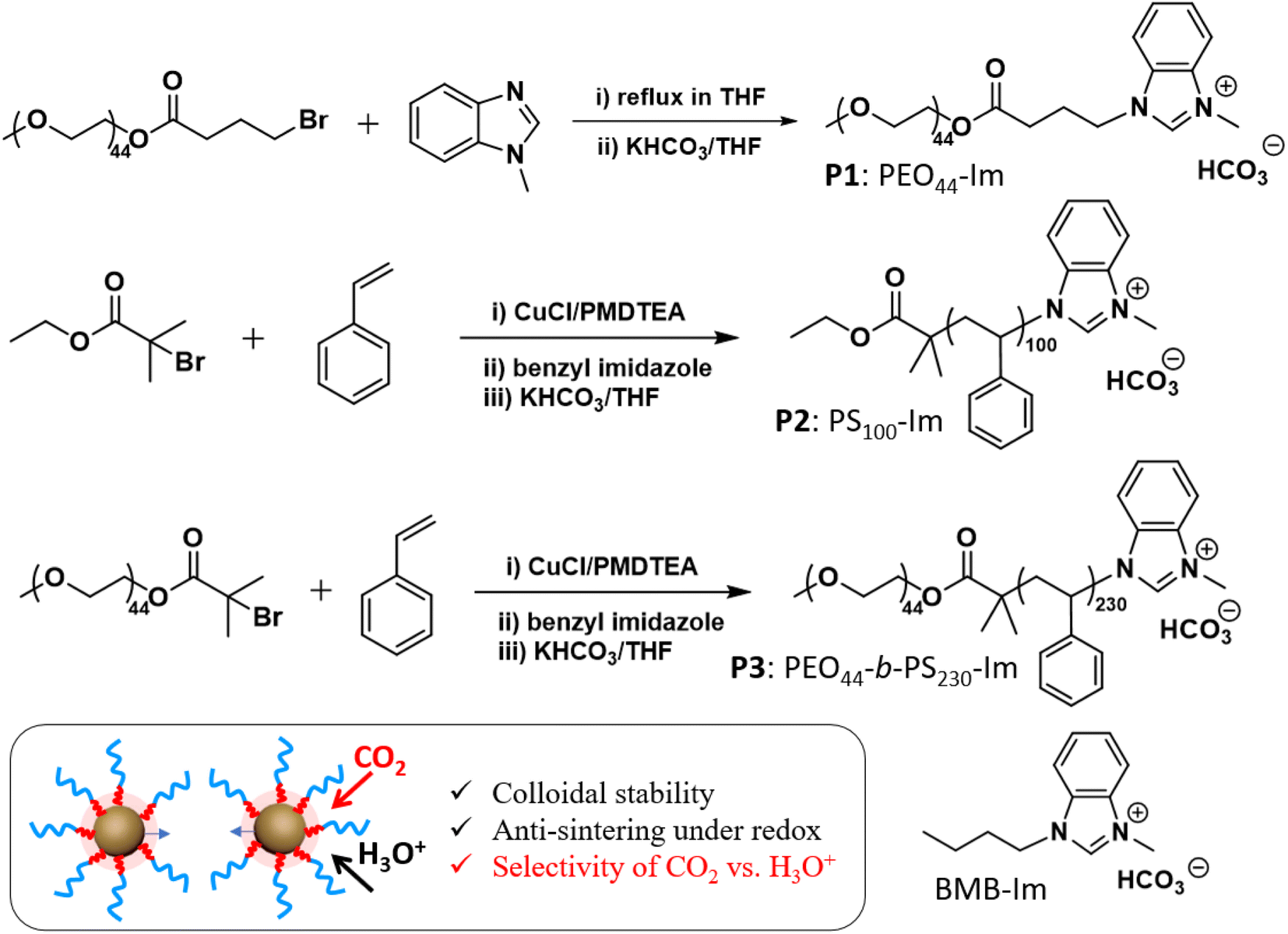 | ||
| Scheme 1 Synthesis of three Im-terminated polymer ligands, including PEO44–Im (P1), PS100–Im (P2), PEO44-b-PS230–Im (P3), and molecular BMB–Im. | ||
2. Results and discussion
Three different polymer methylbenzimidazolium salts with bicarbonate counter ions were used as polymer NHC precursors (see ESI† for synthetic details). The first polymer, methylbenzimidazolium-terminated PEO (P1, PEO44–Im, Mn 2 kg mol−1), was prepared through the esterification of monohydroxy PEO with 4-bromobutyric acid and further alkylation with 1-methylbenzimidazole (Scheme 1). Methylbenzimidazolium-terminated polystyrene (P2, PS100–Im, Mn 10.7 kg mol−1, Đ = 1.14) and the amphiphilic BCP (P3, PEO44-b-PS230–Im, Mn 27.0 kg mol−1, Đ = 1.18) were synthesized from atom transfer radical polymerization (ATRP). The end halide group was further converted through the alkylation with 1-methylbenzimidazole under reflexing in N,N-dimethylformamide with trace amount of KI as the catalysts, similarly to our previous reports.44–46 The same alkylation procedures were carried out for PEO44–Im (P1), PS100–Im (P2), PEO44-b-PS230–Im (P3) and 1-butyl-3-methyl-1H-benzimidazolium bromide (BMB–Im). The halide ions were further exchanged with excess KHCO3 in tetrahydrofuran (THF) (Scheme 1). To remove the residual KCl, the polymer solution was purified by passing through a silica gel column twice. The final product of three polymers was obtained by precipitation and dried under vacuum. The BMB–Im was used for surface modification directly in the solution of KHCO3 as described below. The characterization details are summarized in ESI (Fig. S1–S4†).AuNPs (diameter 14 ± 1.7 nm, Fig. S15†) were synthesized and modified by polymer NHCs through a “grafting to” method as reported previously.36,46 To ensure the ohmic contact between AuNPs and the electrode, citrate-capped AuNPs were first adsorbed on activated carbon (Printex U, ca. 50 nm nanospheres). Typically, 30 mg of activated carbon was dispersed in 10 mL of ethanol and further mixed with the stock solution of AuNPs (120 mL in water with a concentration of 0.1 mg mL−1). After stirring overnight, Au/C (∼40 wt% Au) catalysts powder was collected by centrifugation. Au/C catalysts were further modified with polymer ligands in THF (see details in ESI†). Au/C catalysts modified by BMB–Im was carried out in 0.1 M of NaHCO3 solution containing BMB–Im. The unbound ligands were removed through two centrifugation cycles. The surface grafting was first confirmed by Fourier-transform infrared spectroscopy (FT-IR) (Fig. S5†). For example, PS100–Im shows typical aromatic C–H stretching at 3025 cm−1, aliphatic C–H stretching at 2916 (as) and 2814 (s) cm−1 and aromatic ring breathing mode at 1600–1400 cm−1. Similar vibrational peaks were observed for PS-grafted Au/C catalyst. The formation of NHC on the surface of AuNPs was examined by X-ray photoelectron spectroscopy (XPS, Fig. S6†). In case of BMB–Im, a well-resolved N 1s peak at 400.2 eV was seen for Au/C grafted by BMB–Im, characteristic for the conversion of the charged benzimidazolium to benzimidazole NHC.47,48 The grafting density of ligands was measured by thermogravimetric analysis through the weight loss of polymer ligands (Fig. S7†). The grafting density is 1.2 chains per nm2 for P1, 0.8 chains per nm2 for P2, and 0.6 chains per nm2 for P3, respectively. While all three polymers showed reasonably high grafting density, P1 had a slightly higher grafting density, due to its low molecular weight.
To quantify the accessibility of Au catalysts after surface modification with NHC ligands, electrochemically active surface area (ECSA) of AuNPs were examined using cyclic voltammetry (CV, Fig. 1a). The typical CVs were measured in 0.5 M H2SO4 saturated with N2 a scan rate of 100 mV s−1. In the cathodic scan, the reduction peak was seen at 1.15 V vs. RHE, assigned to the reduction of surface oxygenated monolayer. The peak area is proportional to the electrochemically active surface.49 In the absence of ligands, as shown in Fig. 1b, Au/C shows an ECSA of 0.25 ± 0.01 cm2 μg−1. With hydrophilic PEO–NHC, Au–P1 has a minimum change of its ECSA of 0.23 ± 0.001 cm2 μg−1. Hydrophobic PS, on the other hand, decreases the accessibility of Au. Au–P2 and Au–P3 have an ECSA of 0.14 ± 0.01 and 0.13 ± 0.01 cm2 μg−1, respectively. The CVs in 0.1 M KHCO3 are given in Fig. 1c and d. Under N2, a similar catalytic reduction for Au/C and Au–P3/C was observed. For Au–P3, there was an increase of its current density under CO2, indicating its high selectivity toward CO2 as compared to that of Au/C. Similar trend could be observed for Au–P1 and Au–P2 (Fig. S8†). The typical linear sweep voltammograms (LSVs) are displayed in Fig. 1e (normalized to geometric electrode surface area) and Fig. 1f (normalized to ECSA). Interestingly, all polymer NHCs modified Au catalysts showed higher activity than Au/C. The positive shift of the onset potentials and the increase of current density were more obvious when considering the intrinsic activity of AuNPs as shown in Fig. 1f.
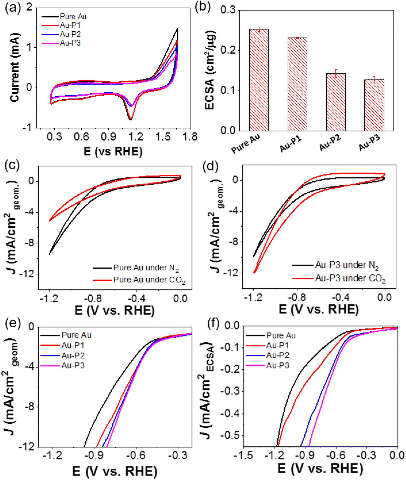 | ||
| Fig. 1 (a) CVs of Au/C with different polymer ligands measured in N2-saturated 0.5 M H2SO4 with a scan rate of 100 mV s−1. (b) ECSAs of AuNPs modified with various ligands. (c) and (d) CV curves of AuNPs (c) and Au–P3 (d) under N2 (black) and CO2 (red). (e) and (f) LSV curves measured in CO2-saturated 0.1 M KHCO3 at a scan rate of 10 mV s−1 normalized to (e) geometric area of electrodes and (f) ECSA of AuNPs. | ||
More quantitatively, the electrocatalytic activity and selectivity of all catalysts were further analyzed through faradaic efficiency (FE) and their partial current density toward CO (JCO) and H2 (JH2). Electrocatalytic CO2 reduction was carried out in a custom-made H cell separated with a Nafion membrane using 0.1 M KHCO3 as a supporting electrolyte. Au/C without NHC ligands yielded CO with FE of 64 to 76% in the potential range of −0.7 to −1.1 V. Those CO FE values are in good agreement with previous literatures.6,50 The partial current density of JCO, calculated from CO FE and the total current density at a corresponding potential, is plotted in Fig. 2b. The JCO increased with reductive potential, suggesting a faster kinetic turnover of CO2. At −1.1 V, JCO reached 12.4 mA cm−2; with a similar trend, JH2 reached 7.0 mA cm−2. Interestingly, the product ratio of CO/H2 is approximately 2.5 for unmodified Au/C in the potential range of −0.7 to −1.1 V (Fig. 2c). Since both CO and H2 are 2e− reduction products, the selectivity of CO2 over protons (or water) reduction is about 2.5 times on NHC-free AuNPs.
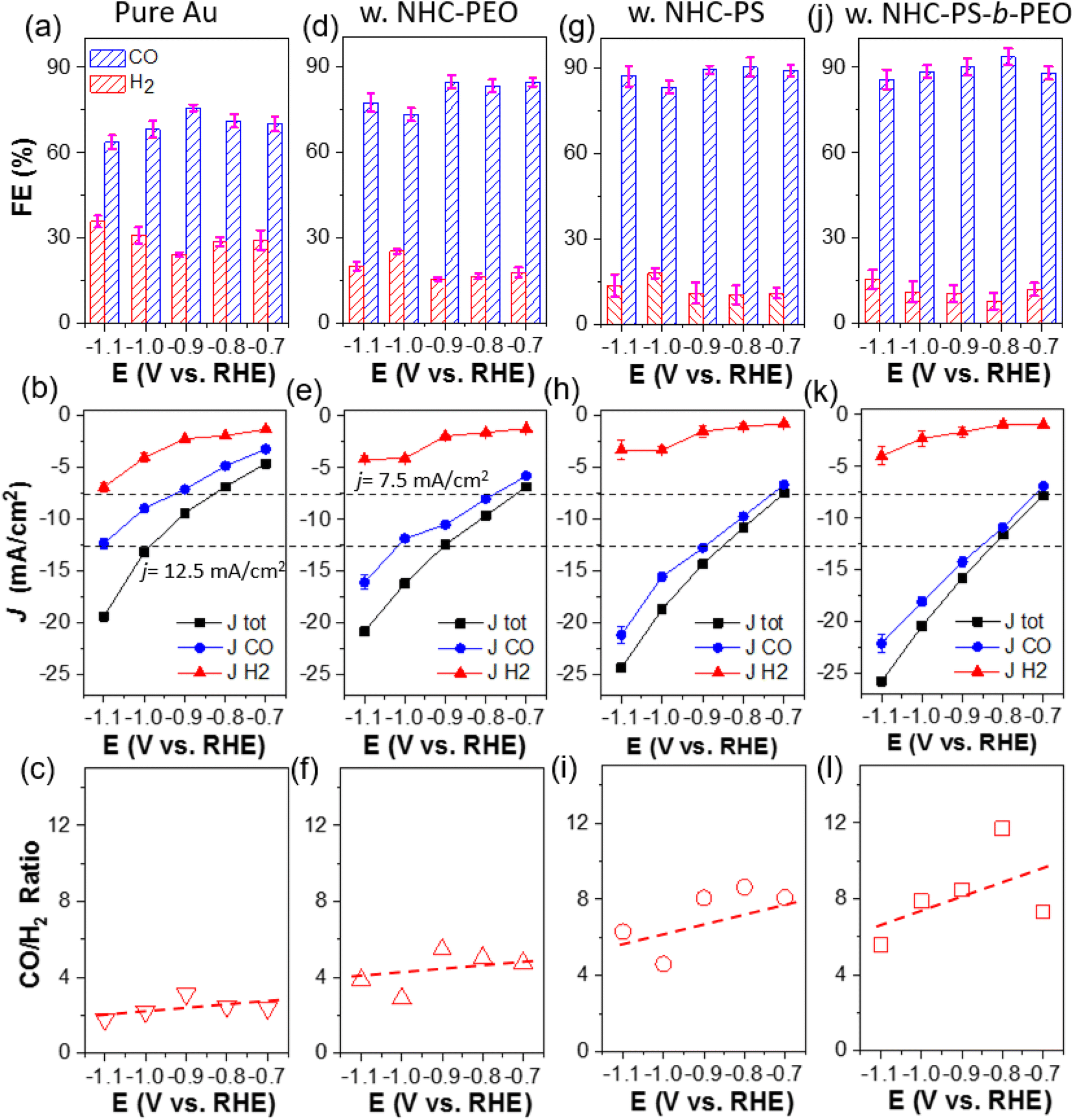 | ||
| Fig. 2 Electrocatalytic performance of CO2 reduction on different catalysts: FE, (partial) current density and product ratio (ordered vertically) using pure Au (a)–(c), Au–P1 (d)–(f), Au–P2 (g)–(i) and Au–P3 (j)–(l). All tests were carried out in CO2 saturated 0.1 M KHCO3. | ||
With polymer NHCs, the CO FE increased for all three catalysts. Au–P2 and Au–P3 showed similar CO FE of 85–95% at −0.7 to −1.1 V (Fig. 2g and j). Without hydrophobic PS, the CO FE of Au–P1 was around 80% (Fig. 2d), slightly lower than that of Au–P2 and Au–P3. The JCO also increased along with the hydrophobicity of polymer NHCs. At −1.1 V as an example, the JCO of Au–P1 was 16.1 ± 0.7 mA cm−2; while, the JCO of Au–P2 and Au–P3 reached 21.2 ± 0.8 and 22.1 ± 0.9 mA cm−2, close to 2-times higher than that of Au/C without NHC ligands. The JH2, however, did not follow the same trend. All polymer NHC ligands had a similar impact on JH2 and the decrease of JH2 was independent of polymer hydrophobicity. At −1.1 V, the JH2 of Au–P1, Au–P2 and Au–P3, was 4.2 ± 0.7, 3.4 ± 0.9 and 4.0 ± 0.9 mA cm−2 respectively, that is about 50% of JH2 of pure Au. As a result, the product ratio of CO/H2 increased with the hydrophobicity of polymers. At −0.9 V, the CO/H2 ratio of Au–P1 is 5.5; and the CO/H2 ratio of Au–P2 and Au–P3 is 8.1 and 8.5, respectively, that is about 3 times more selective to reduce CO2 in comparison with Au/C. The role of polymer NHCs in CO2 reduction, as we deducted from those results, is likely two-folded. First, polymer NHCs, regardless of their hydrophobicity, would suppress the catalytic activity to reduce protons. The decrease of JH2 was seen in all three polymer ligands, although the grafting density and hydrophobicity of polymer ligands were different. Secondly, the hydrophobic PS would provide such a microenvironment to improve CO2 selectivity and activity. When modifying Au/C with P1, the total current density (Jtot) did not show a noticeable increase but the JH2 had an obvious decrease. In the presence of hydrophobic PS, the increase of JCO (nearly no impact on JH2) suggests that the binding motif and polymer hydrophobicity likely play a very different role in CO2 electroreduction. Furthermore, since the JCO as well as the CO/H2 ratio of Au–P2 and Au–P3 were only marginally different, the PEO chains of amphiphilic P3 would have a minimum impact on CO2 selectivity.
To distinguish the impact of polymers and the binding motif on the catalytic selectivity, AuNPs capped by the molecular NHC BMB–Im were examined for CO2 electroreduction under identical conditions (Fig. 3a). The comparation of CO and H2 FE are given in Fig. 3b and c. Interestingly, Au/C modified by BMB–Im showed very similar CO FE as Au–P1. This could also be confirmed through nearly identical CO/H2 ratio close to 4 within same potential range (Fig. 3d). Both of them showed lower selectivity toward H2 as compared to unmodified Au/C, suggesting that the NHC binding motif, instead of polymer chains, is responsible for the catalytic suppression of HER. Note that, Au modified by P1 had a higher activity as compared to that with BMB–Im (Fig. S8†). For the partial current density, the JCO of Au–P1 is 8.0 and 11.8 mA cm−2 at −0.8 and −1.1 V, respectively (Fig. 3e), about 1.5-times higher than those of Au–BMB–Im under the same potential. The activity toward HER shows a very similar trend. The higher activity for Au–P1 is likely due to the lower grafting density where the longer PEO chains would have much greater steric hindrance on the surface of AuNPs.
 | ||
| Fig. 3 (a) Scheme of BMB–Im and PEO–NHC modified AuNPs through Au–C binding. Catalytic selectivity to CO and H2 using Au–BMB–Im (b) and Au–NHC–PEO (c). (d) Product ratio and (e) current density analysis of Au–BMB–Im and Au–NHC–PEO. | ||
A number of previous studies have suggested the possible electronic perturbation of NHCs to surface atoms of NP catalysts.39,51–53 NHCs bind with metal through the lone pair electrons on C; as a result, the σ donation of NHCs to the empty d orbitals of bound metal atoms would increase the electronic density of surface atoms of NP catalysts. As an electrophile, CO2 favors the binding to electron-rich surface. Using in situ produced CO as a probe molecule, we used attenuated total reflectance surface-enhanced infrared absorption spectroscopy (ATR-SEIRAS) to measure the vibrational frequency of CO. A chemically deposited polycrystalline Au film upon reflecting Si prism was used as a working electrode. While Au has very weak binding with CO, the surface plasmon enhances the peak intensity significantly. At −0.3 V, the infrared spectra could be collected using the catalysts without bias as a background. In addition to the gaseous CO2 peak centered at 2350 cm−1, a new peak appeared at ∼2120 cm−1, assigned to the bound CO on the surface of Au (Fig. 4a and b).54 After surface modification with P3 as an example, the bound CO shifted to 2108 cm−1 (note the CO peak position is potential-dependent and it is compared at the same potential). As a π acceptor, CO with a lower stretching frequency indicates the electron-rich surface of AuNPs when modified with polymer NHCs. A high surface electron density through the σ-donation of NHCs likely favors CO2 reduction over HER.43,55,56 In addition, previous studies have demonstrated that NHCs potentially can stabilize the CO2 adduct and intermediate CO2˙− through hydrogen bonding,57–59 also positively improving the selectivity for CO2 reduction.
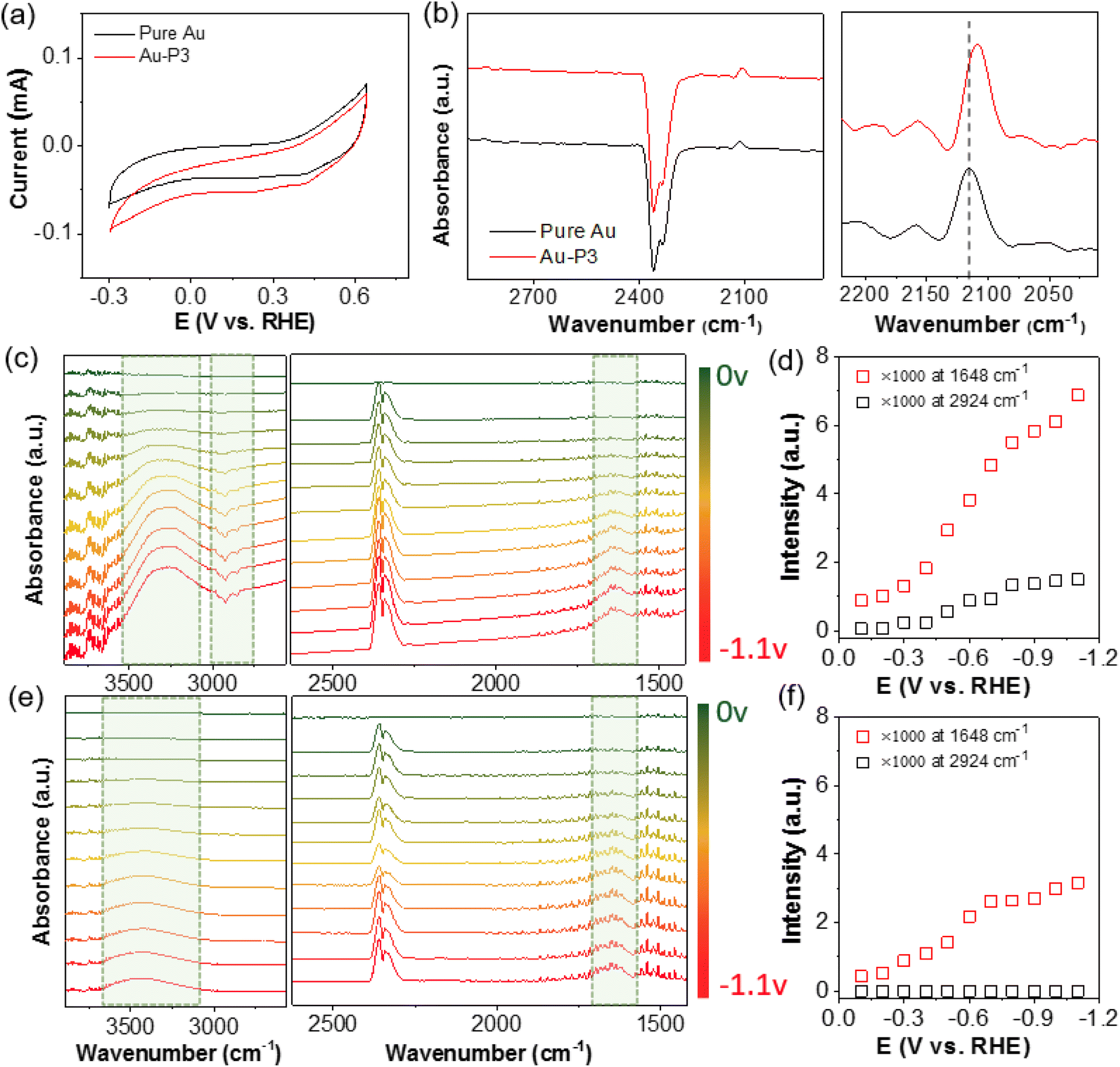 | ||
| Fig. 4 Infrared spectroscopical study of Au electrodes with polymer NHC ligands. (a) CV scans in N2 saturated 0.1 M KHCO3 and (b) in situ ATR-SEIRAS spectra obtained at −0.3 VRHE of AuNPs and Au–NHC–PS-b-PEO, respectively. In situ ATR-SEIRAS spectra and vibrational peak intensity study for Au–NHC–PS-b-PEO (c) and (d) and pure AuNPs (e) and (f) in CO2-purged 0.1 M KHCO3 under various reductive potentials. The spectra in (c) and (e) are background subtracted at 0 V. | ||
To gain more insights into the surface status at the electrode–electrolyte interface, especially in the presence of polymer NHCs, ATR-SEIRAS spectra were recorded on Au film electrodes during chronoamperometry scans under different potentials. Using the Au electrodes without bias as the background for all spectra, the positive peaks (pointing up) in the absorption model were from the yielded (or surface adsorbed) species during CO2 electroreduction; while, the negative peaks (pointing down) arose from the desorbed species, e.g., ligands. In Fig. 4e, the ATR-SEIRAS spectra on pure Au are given in the potential range of 0 to −1.1 V under constant-potential electrolysis. With the change of the negative bias, there were two positive peaks appeared, e.g., a broad peak at 3300–3600 cm−1 as the O–H stretching (νO–H) and a well-defined peak at 1640 cm−1 as the O–H bending (δO–H). The νO–H peak centered at 3400 cm−1 was broad as a typical characteristic for disordered water molecules. Those peak positions, along with the CO2 doublet at 2361 and 2336 cm−1,60 agree very well the reported O–H vibrational frequency.33,61,62Fig. 4f shows the plot of the δO–H peak intensity as a function of potential. At around −0.3 V, there was a quick increase of the δO–H peak (νO–H in the similar trend), suggesting the re-orientation and adsorption of water as H-down on the electrode to couple with CO2 reduction.63 The peak intensity saturated at around −0.8 V, known as the formation of densely packed layer of water for fast proton transfer.61
In the presence of polymer NHCs, the ATR-SEIRAS spectral features were obviously different. First, there was a large shift of the νO–H peak along with the peak sharpening (Fig. 4c). For Au–P3, the O–H stretching of adsorbed water downshifted to approximately 3300 cm−1 with two shoulders at 3370 and 3247 cm−1. In the absence of hydrophobic PS, Au–P1 and Au–BMB–Im do not show similar peak shift (Fig. S9†). The down shift of the νO–H peak indicates the formation of stronger hydrogen bonds of water, as compared to that without hydrophobic PS. This phenomena has been demonstrated in the phase transition of liquid water to ice.64 In the presence of hydrophobic PS ligands, water molecules were likely confined at the electrode–electrolyte interface. With strong hydrogen bonding, water molecules form clusters presumably surrounded by hydrophobic ligands. Second, the peak intensity of adsorbed water showed a similar increased trend as that of unmodified Au; while, the peak intensity was much pronounced. The peak intensity was nearly doubled, and no saturation was observed in this case. Because the densely packed layer of water was only limited by the surface area of Au, it is likely that multiple layers of water were associated in Au–P3. Since strongly hydrogen bonded water did not show any peak shift with potential, re-orientated water was presumed to be stacked in the hydrophobic microenvironment. Lastly, negative peaks at 3100–2800 cm−1 were seen at an onset potential of −0.5 V. Those peaks were assigned to the C–H bond stretching of sp2 and sp3 C of polymer backbones and side chains (also discussed in Fig. 8).65 This was confirmed by the control of unmodified Au where no new peaks were observed in this region. We attributed those peaks to the dissociation of polymer NHCs from the electrode surface, although the peak intensity saturated quickly at −0.8 V (Fig. 4d).
Hydrophobic polymer NHCs as surface ligands were thought to alter the accessibility of Au in terms of the mass transfer during electrocatalysis. In view of CO2 electroreduction as proton-coupled electron transfer, we further investigated whether the interface of hydrophobic polymers and Au would limit the diffusion of hydrated ions. Three different molecular probes were chosen to examine the interfacial mass transfer process during electrocatalysis. Specifically, the diffusive properties described by Randles–Ševčík equation can be determined by reversible redox under different scan rates, as described below:66
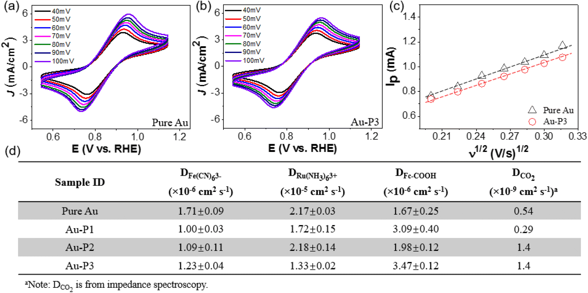 | ||
| Fig. 5 Interfacial diffusive properties of all catalysts. (a) CV scans of AuNPs and (b) Au–P3 measured with 50 mM K3Fe(CN)6 at various scan rates. (c) Linear relationship between peak current (Ip) and the square root of scan rates for pure Au and Au–P3. (d) Summary of diffusion coefficient (D) using various probe molecules including Fe(CN)63−, Ru(NH3)63+, Fc–COOH, and CO2. | ||
More hydrophobic probes, like ferrocenecarboxylic acid (Fc–COOH), behave very differently from those strongly hydrated probes. Polymer NHCs did not slow down the diffusion of Fc–COOH. In case of Au–P1 and Au–P3, the measured D0 of Fc–COOH was about 2-times higher than that of Au/C. The increase of D0 of Fc–COOH is likely due to the hydrogen bonding of carboxylic acid and PEO (Fig. S12†). Unlike small molecular ligands that usually form a crystalline self-assembly monolayer,68 the low grafting density of polymer ligands provides the diffusive channels to allow the redox reactions. For the CO2 diffusion, electrochemical impedance spectroscopy (EIS) was used to fit the diffusion of CO2 at −0.8 V over a frequency range of 100 kHz to 1 Hz (see Fig. S13 and details on data fitting in ESI†). The diffusion coefficient of CO2 was close to 1.4 × 10⁻⁹ cm2 s−1 for Au–P2 and Au–P3 with hydrophobic PS domain, that is about 3 times greater than that of Au/C. Although the diffusion coefficient from the impedance spectroscopy does not differ the diffusion of CO2 from proton contribution from proton reduction was much smaller on Au catalysts modified by hydrophobic polymers (>90% CO FE). The increase of the diffusion coefficient of CO2 should be responsible for the high selectivity for CO2 over HER. Together with the SEIRAS results, one possible mechanism is that hydrophobic PS domains provide strong dehydration to CO2 that allows faster conversion of HCO3− ions to CO2;69 therefore, the local CO2 concentration is higher than those without PS domains, similar to the CO2 concentrating mechanism in photosynthesis. Therefore, hydrophobic polymer ligands would create a localized microenvironment that enriches CO2 close to the active Au surface.
To investigate the effect of hydrophobic polymer ligands on the solvation structure around AuNPs, molecular dynamics (MD) simulations were carried out on a gold layer tethered with PS chains consisting of 66 repeating units (Fig. 6a). Fig. 6b shows the density profiles along the z axis, perpendicular to the Au surface. At a surface coverage of 0.89 chains per nm2, the polymer ligands created a sufficiently hydrophobic environment, with a clearly delineated bulk region at z > 11.8 nm and a water poor polymer layer for z < 11.8 nm. Yet, water peaks are found inside the polymer layer, corresponding to pockets of water embedded in hydrophobic PS. The differences in water structuring can be clearly identified in the oxygen–oxygen (Ow–Ow) radial distribution functions (RDFs) for water molecules in these two domains, as shown in Fig. 6c. While all RDFs show a first peak at r = 0.28 nm, as expected for bulk water, the peak heights are substantially different, with g = 2.8 for the bulk water region and g = 16 for the polymer layer. The first minimum and subsequent peak structures in the RDFs remain much higher than one, indicating strong aggregation but lack of longer-range order for water in the polymer region. Examining the simulation trajectories indicates that, despite the formation of localized water clusters, these clusters are dynamic and loosely connected to each other. Similar clustering is also confirmed with various CO2 concentrations (Fig. S14†). Those results agree well with our experiments where dynamically clustered water was seen for AuNPs modified by hydrophobic PS. In addition, polymer chains effectively act as sorbent materials for CO2 as suggested by its density profiles shown in Fig. 6b. There is a significantly higher density of CO2 in the polymer layer than in the bulk water region, consistent with the increased CO2 localized concentration and, therefore, reduction activity for polymer-modified AuNPs.
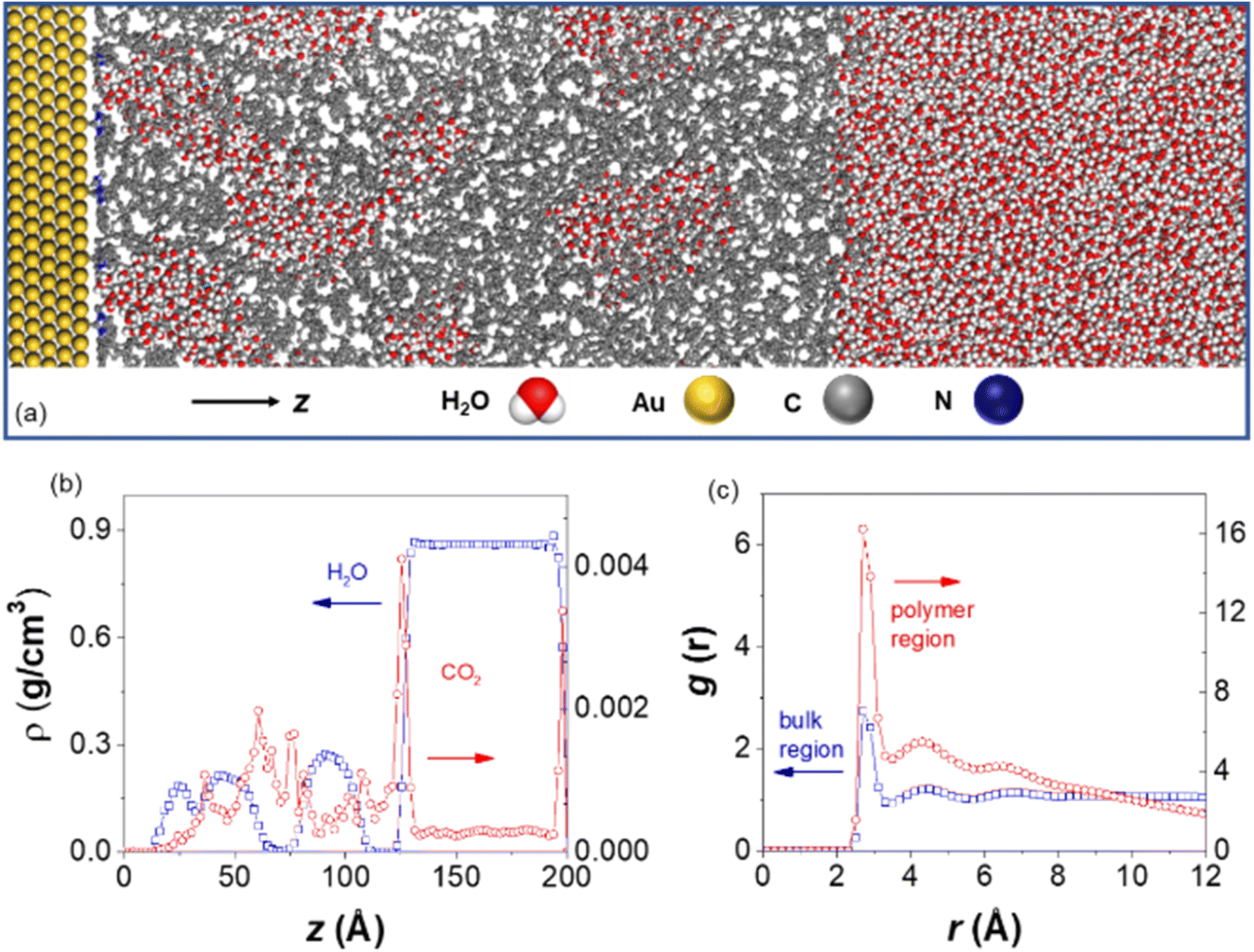 | ||
| Fig. 6 (a) Illustration of the simulation setup, with the Au, C, N, O, H atoms represented in yellow, grey, blue, red, and white, respectively; (b) density profiles as a function of z coordinates, with water and CO2 shown in blue and red; (c) Ow–Ow radial distribution function, analyzed for water molecules above z = 11.8 nm (bulk region, blue) and those below z = 11.8 nm (polymer layer, red). | ||
We finally investigated the electrochemical stability of Au catalysts to confirm the binding stability of polymer NHCs with Au surface. Fig. 7a shows the chronoamperometry (i–t) at −1.0 V. Without polymer NHCs, Au/C had a fast activity decay. The steady-state current decreased from −0.92 to −0.33 mA after electrolysis for 1 h, about 36% current retention. The current loss is attributed to the sintering of AuNPs under reductive potentials as confirmed by transmission electron microscopy (TEM, Fig. 7d). The fast aggregation and sintering of AuNPs as large as 50 nm were observed after 1 h, similar to the previous reports.8 More quantitatively, the ECSA of AuNPs showed an 83% loss after electrolysis for 1 h at −1.0 V (Fig. 7c). In contrast, the electrocatalytic stability of AuNPs modified by all three polymers was greatly improved (Fig. 7b). The current retention was approximately 70%, regardless of the hydrophobicity of polymer NHCs (Fig. 7a). The ECSA of AuNPs agreed well with the activity retention; and the accessible surface area retention was 82.7%, 84.6% and 82% for Au–P1, Au–P2 and Au–P3, respectively (Fig. 7c). The steady-state current retention for Au–P2 and Au–P3 was approximately 80%. Fig. 7e shows the morphologic evolution of AuNPs capped by P3 (see Fig. S15† for more images). As confirmed by TEM images (Fig. 7e), AuNPs with polymer ligands showed structural integrity under electrolysis for 1 h at −1.0 V. The average size of Au–P3 is 15.6 ± 1.1 nm after electrolysis, close to their initial size of 14 ± 1.7 nm. Polymer NHCs work as a stabilization agent to prevent AuNPs from interparticle sintering, although there is a small decrease of activity. The measured stability of AuNPs modified by polymer NHCs is consistent with previous results on AuNPs and Pd/C.9,43,70
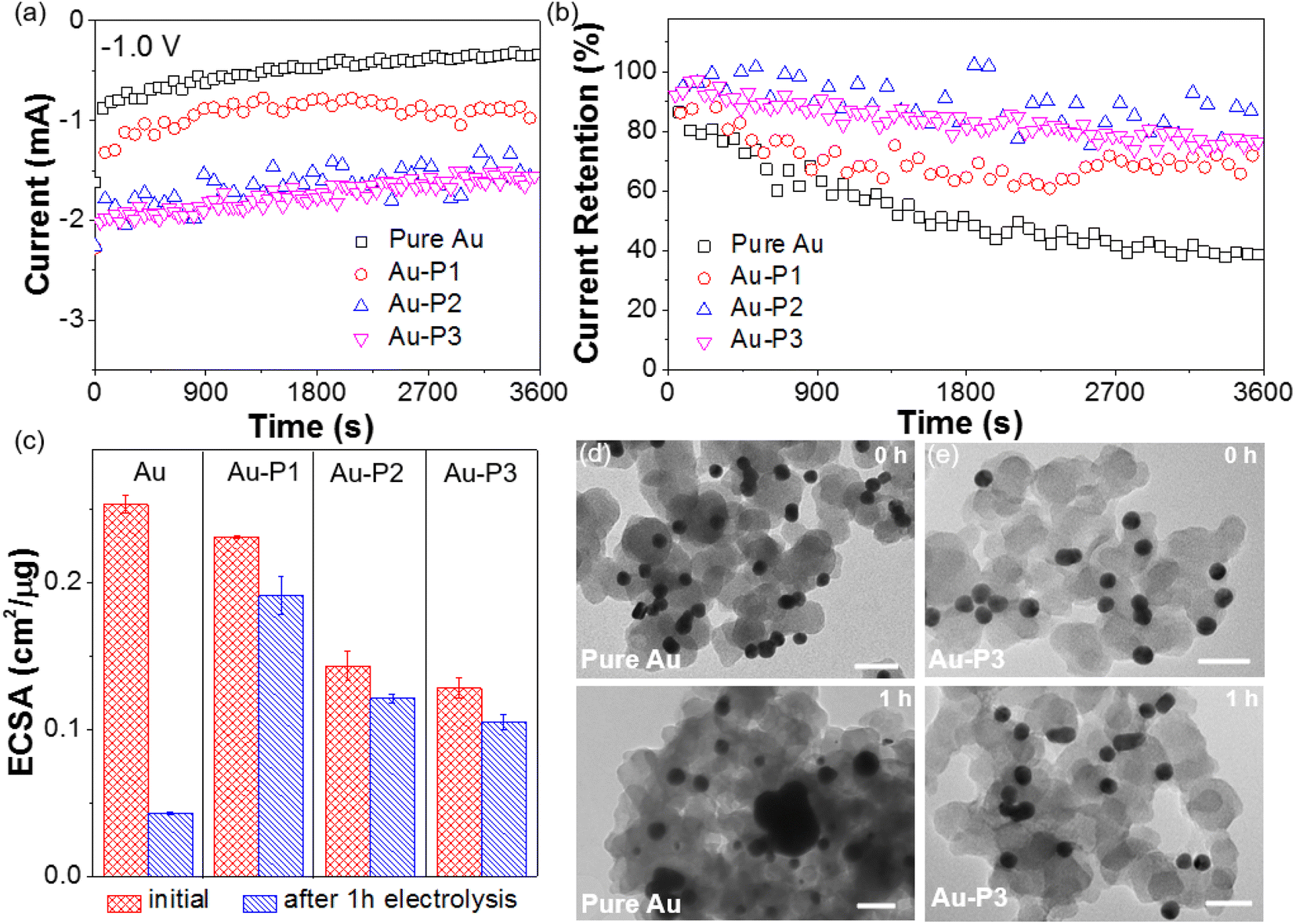 | ||
| Fig. 7 Stability measurement using i–t curves (a), current retention (b) and ECSA (c). The experiments were carried out using constant-potential electrolysis at −1.0 V for 1 h. TEM images of pure Au (d) and Au–P3 (e) loaded on carbon before (top) and after (bottom) CO2 electroreduction for 1 h. All scale bars are 40 nm. | ||
Since the ATR-SEIRAS results at different potential (see Fig. 4) suggested the possible removal of polymer NHCs under reductive potentials, the spectroscopic studies were further carried out to examine the electrochemical stability of polymer NHCs during CO2 electroreduction. The in situ ATR-SEIRAS spectra were collected using constant-potential electrolysis. At −0.8 V, the spectra of Au modified by P3 were collected using the spectrum without bias as a background. Fig. 8a shows the desorption of polymer NHC. The negative peak appeared at ∼2924 cm−1 was assigned to the sp3 C–H bond stretching, similar to the result under different potentials given in Fig. 4c. The peak intensity at 2924 cm−1 as a function of time is, therefore, a measure of the desorption kinetics of NHCs on electrode surface (Fig. 8c). At first 20 min, there was a continuous increase of the peak intensity; and this trend saturated after 20 min. We measured the ATR-SEIRAS spectrum of the electrode after electrolysis for 45 min. There were clearly remaining polymer NHCs appeared at the same wavenumber (Fig. 8d). We assigned the initial surface desorption as the reconfiguration of polymer NHCs on the surface of the Au electrode. This could be due to the surface polarization under potential or the localized charge effect of Au surfaces.71,72 Even though the quantification of ligand retention cannot be determined from this measurement, polymer NHCs with low grafting density could mostly stabilize NPs against sintering. As a control, we examined another thiol-terminated BCP of PS267-b-PEO44. Au–thiolate binding was unstable under CO2 electroreduction as reported previously.8,73 PS267-b-PEO44 had a similar spectral feature of surface desorption. However, it showed a fast and burst desorption behavior (Fig. 8b). Those thiolate polymer ligands completely desorbed under bias. This could be confirmed by the spectrum collected after electrocatalysis for 45 min. A complete loss of thiolated polymers on Au was seen in the first 5 min. Those results suggested that Au–thiolate was not electrochemically stable under reductive conditions; and moreover, thiolate ligands did not provide the stability for AuNPs during CO2 reduction as reported by Alivisatos8 and others.9
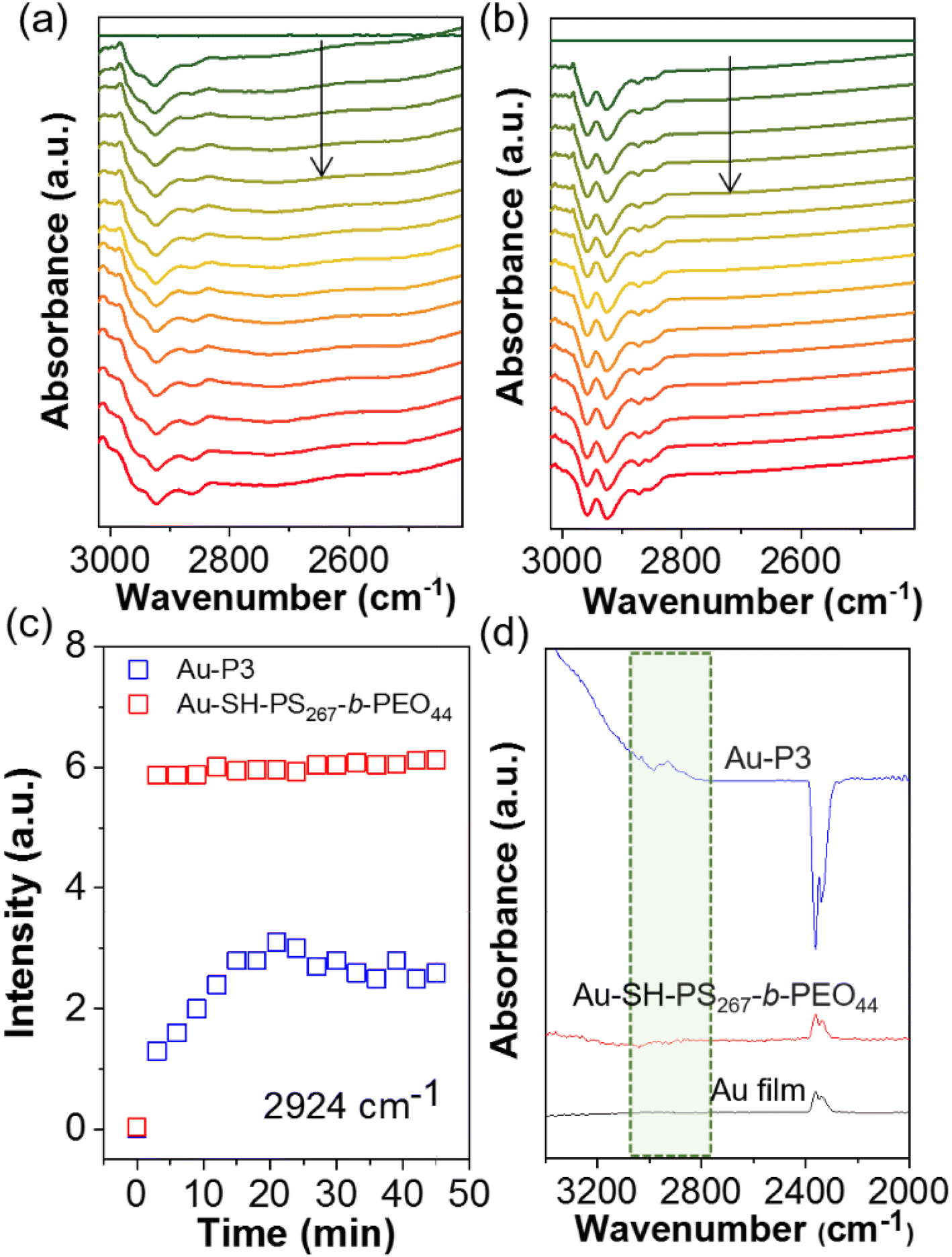 | ||
| Fig. 8 In situ ATR-SEIRAS spectra of surface polymer modified electrode demonstrating the chemical stability of NHC ligands to counterpart thiol ligands. In situ ATR-SEIRAS spectra of (a) Au–NHC–PS-b-PEO and (b) Au–SH–PS267-b-PEO44 at −0.8 V on Au film electrode in CO2 saturated 0.1 M KHCO3 electrolyte. (c) The desorption vibrational peak intensity at 2924 cm−1 against reaction time. (d) The adsorption peak intensity of different electrodes after electrocatalysis under −0.8 V. Blue: Au–P3, red: Au–SH; dark: Au film. | ||
3. Conclusion
In summary, we have successfully demonstrated the utilization of N-heterocyclic carbenes (NHCs) as a binding motif in conjunction with polymer hydrophobicity to exert control over substrate accessibility at the catalyst–electrolyte interface of gold nanoparticles (AuNPs) under redox conditions, as well as enhancing their long-term stability. Three distinct types of polymer ligands with different hydrophobicity/hydrophilicity were meticulously designed to modify AuNPs through NHC–Au binding. Irrespective of their hydrophobicity, AuNPs modified with polymer NHCs exhibited remarkable improvements in catalytic activity and selectivity. Notably, both homopolymer PS and PEO-b-PS NHCs, incorporating hydrophobic PS segments, exhibited a significant increase in selectivity for CO2 reduction, achieving a remarkable CO faradaic efficiency of up to 95%. Moreover, the presence of any of the polymer NHCs led to a 50% reduction in the partial current density attributed to hydrogen formation. Importantly, the hydrophobic nature of the polymer ligands resulted in a twofold increase in the partial current density for CO formation compared to unmodified AuNPs or those modified with hydrophilic PEO. While all polymers did not impede ion diffusion, hydrophobic polymers appeared to influence the localized hydrogen bonding network of water, as evidenced by the outcomes of attenuated total reflectance surface-enhanced infrared absorption spectroscopy (ATR-SEIRAS) supertropical studies and MD simulations. Furthermore, the hydrophobic nature of polymer ligands clustered water molecules and facilitated an enrichment in the local CO2 concentration, thereby enabling more efficient CO2 reduction. Spectroelectrochemistry data obtained through ATR-SEIRAS suggested the relatively stable nature of the polymer NHC ligands under reductive conditions, as compared to thiol-terminated PS ligands. Collectively, our findings regarding the integration of robust NHC ligands with hydrophobic polymers provide valuable insights into the design of bioinspired hybrid catalysts for highly selective CO2 reduction.Data availability
The datasets supporting this article have been uploaded as part of the ESI.†Author contributions
J. H. and S. S. designed and directed the project. Q. L., M. M., M. L., and K. W. carried out the CO2 reduction experiments and spectroscopic studies. H. D. designed and synthesized all polymers. J. T. and P. B. planned and carried out the simulations. J. A. and G. U. designed the molecular carbenes. S. S. and S. L. S. did the TGA and XPS measurements. J. H. and Q. L. took the lead in writing the manuscript. All authors discussed the results and provided feedbacks on manuscript.Conflicts of interest
The authors declare that they have no conflict of interest.Acknowledgements
JH and SS is grateful for the financial support from the National Science Foundation (CHE 2102245 to JH and CHE-2102290 to Sun on experiments). PB acknowledges the support from the National Science Foundation (CBET 2144360 on simulation). The TEM images were obtained at the Biosciences Electron Microscopy Facility at the University of Connecticut. The computer simulations used resources of the National Energy Research Scientific Computing Center (NERSC) through allocation ERCAP0021594 and of the Advanced Cyberinfrastructure Coordination Ecosystem (ACCESS) through allocation CTS190069. This work was also partially supported by the Green Emulsions Micelles and Surfactants (GEMS) Center of the University of Connecticut.References
- Z. Yin, G. T. R. Palmore and S. Sun, Trends Chem., 2019, 1, 739–750 CrossRef CAS.
- Z. Yin, J. Yu, Z. Xie, S.-W. Yu, L. Zhang, T. Akauola, J. G. Chen, W. Huang, L. Qi and S. Zhang, J. Am. Chem. Soc., 2022, 144, 20931–20938 CrossRef CAS PubMed.
- D. Gao, R. M. Arán-Ais, H. S. Jeon and B. Roldan Cuenya, Nat. Catal., 2019, 2, 198–210 CrossRef CAS.
- S. Li, A. V. Nagarajan, D. R. Alfonso, M. Sun, D. R. Kauffman, G. Mpourmpakis and R. Jin, Angew. Chem., Int. Ed., 2021, 60, 6351–6356 CrossRef CAS PubMed.
- S. Li, A. V. Nagarajan, X. Du, Y. Li, Z. Liu, D. R. Kauffman, G. Mpourmpakis and R. Jin, Angew. Chem., Int. Ed., 2022, 61, e202211771 CrossRef CAS PubMed.
- W. Zhu, R. Michalsky, Ö. Metin, H. Lv, S. Guo, C. J. Wright, X. Sun, A. A. Peterson and S. Sun, J. Am. Chem. Soc., 2013, 135, 16833–16836 CrossRef CAS PubMed.
- C. Rogers, W. S. Perkins, G. Veber, T. E. Williams, R. R. Cloke and F. R. Fischer, J. Am. Chem. Soc., 2017, 139, 4052–4061 CrossRef CAS PubMed.
- K. Manthiram, Y. Surendranath and A. P. Alivisatos, J. Am. Chem. Soc., 2014, 136, 7237–7240 CrossRef CAS PubMed.
- L. Zhang, Z. Wei, S. Thanneeru, M. Meng, M. Kruzyk, G. Ung, B. Liu and J. He, Angew. Chem., Int. Ed., 2019, 58, 15834–15840 CrossRef CAS PubMed.
- J. Huang, N. Hörmann, E. Oveisi, A. Loiudice, G. L. De Gregorio, O. Andreussi, N. Marzari and R. Buonsanti, Nat. Commun., 2018, 9, 3117 CrossRef PubMed.
- P. Grosse, A. Yoon, C. Rettenmaier, A. Herzog, S. W. Chee and B. Roldan Cuenya, Nat. Commun., 2021, 12, 6736 CrossRef CAS PubMed.
- V. Okatenko, A. Loiudice, M. A. Newton, D. C. Stoian, A. Blokhina, A. N. Chen, K. Rossi and R. Buonsanti, J. Am. Chem. Soc., 2023, 145, 5370–5383 CrossRef CAS PubMed.
- S. Zhao, R. Jin and R. Jin, ACS Energy Lett., 2018, 3, 452–462 CrossRef CAS.
- A. Wadas, A. Gorczynski, I. A. Rutkowska, E. Seta-Wiaderek, E. Szaniawska, M. Kubicki, A. Lewera, M. Gorzkowski, A. Januszewska, R. Jurczakowski, B. Palys, V. Patroniak and P. J. Kulesza, Electrochim. Acta, 2021, 388, 138550 CrossRef CAS.
- A. Goyal, G. Marcandalli, V. A. Mints and M. T. M. Koper, J. Am. Chem. Soc., 2020, 142, 4154–4161 CrossRef CAS PubMed.
- C. W. Li and M. W. Kanan, J. Am. Chem. Soc., 2012, 134, 7231–7234 CrossRef CAS PubMed.
- X. Su, Y. Sun, L. Jin, L. Zhang, Y. Yang, P. Kerns, B. Liu, S. Li and J. He, Appl. Catal., B, 2020, 269, 118800 CrossRef CAS.
- D. Gao, H. Zhou, J. Wang, S. Miao, F. Yang, G. Wang, J. Wang and X. Bao, J. Am. Chem. Soc., 2015, 137, 4288–4291 CrossRef CAS PubMed.
- F. Cai, D. Gao, H. Zhou, G. Wang, T. He, H. Gong, S. Miao, F. Yang, J. Wang and X. Bao, Chem. Sci., 2017, 8, 2569–2573 RSC.
- J.-H. Kim, H. Woo, J. Choi, H.-W. Jung and Y.-T. Kim, ACS Catal., 2017, 7, 2101–2106 CrossRef CAS.
- L.-P. Yuan, W.-J. Jiang, X.-L. Liu, Y.-H. He, C. He, T. Tang, J. Zhang and J.-S. Hu, ACS Catal., 2020, 10, 13227–13235 CrossRef CAS.
- L. Jin, B. Liu, P. Wang, H. Yao, L. A. Achola, P. Kerns, A. Lopes, Y. Yang, J. Ho, A. Moewes, Y. Pei and J. He, Nanoscale, 2018, 10, 14678–14686 RSC.
- C. W. Lee, S.-J. Shin, H. Jung, D. L. T. Nguyen, S. Y. Lee, W. H. Lee, D. H. Won, M. G. Kim, H.-S. Oh, T. Jang, H. Kim, B. K. Min and Y. J. Hwang, ACS Energy Lett., 2019, 4, 2241–2248 CrossRef CAS.
- C. Janáky, D. Hursán, B. Endrődi, W. Chanmanee, D. Roy, D. Liu, N. R. de Tacconi, B. H. Dennis and K. Rajeshwar, ACS Energy Lett., 2016, 1, 332–338 CrossRef.
- S. Huo, Z. Weng, Z. Wu, Y. Zhong, Y. Wu, J. Fang and H. Wang, ACS Appl. Mater. Interfaces, 2017, 9, 28519–28526 CrossRef CAS PubMed.
- X. Zhou, H. Liu, B. Y. Xia, K. Ostrikov, Y. Zheng and S.-Z. Qiao, SmartMat, 2022, 3, 111–129 CrossRef CAS.
- D. Kim, S. Yu, F. Zheng, I. Roh, Y. Li, S. Louisia, Z. Qi, G. A. Somorjai, H. Frei, L.-W. Wang and P. Yang, Nat. Energy, 2020, 5, 1032–1042 CrossRef CAS.
- Q. Zhu, C. J. Murphy and L. R. Baker, J. Am. Chem. Soc., 2022, 144, 2829–2840 CrossRef CAS PubMed.
- L. Lu, S. Zou and B. Fang, ACS Catal., 2021, 11, 6020–6058 CrossRef CAS.
- H. Shang, S. K. Wallentine, D. M. Hofmann, Q. Zhu, C. J. Murphy and L. R. Baker, Chem. Sci., 2020, 11, 12298–12306 RSC.
- Z. Wang, L. Wu, K. Sun, T. Chen, Z. Jiang, T. Cheng and W. A. Goddard III, J. Phys. Chem. Lett., 2018, 9, 3057–3061 CrossRef CAS PubMed.
- J. R. Pankhurst, P. Iyengar, A. Loiudice, M. Mensi and R. Buonsanti, Chem. Sci., 2020, 11, 9296–9302 RSC.
- W. Ge, Y. Chen, Y. Fan, Y. Zhu, H. Liu, L. Song, Z. Liu, C. Lian, H. Jiang and C. Li, J. Am. Chem. Soc., 2022, 144, 6613–6622 CrossRef CAS PubMed.
- S. Sun, Nat. Energy, 2020, 5, 943–944 CrossRef.
- L. Jin, B. Liu, S. S. Duay and J. He, Catalysts, 2017, 7, 44 CrossRef.
- K. Wei, H. Guan, Q. Luo, J. He and S. Sun, Nanoscale, 2022, 14, 11869–11891 RSC.
- F. P. García de Arquer, C.-T. Dinh, A. Ozden, J. Wicks, C. McCallum, A. R. Kirmani, D.-H. Nam, C. Gabardo, A. Seifitokaldani, X. Wang, Y. C. Li, F. Li, J. Edwards, L. J. Richter, S. J. Thorpe, D. Sinton and E. H. Sargent, Science, 2020, 367, 661–666 CrossRef PubMed.
- D. Wakerley, S. Lamaison, F. Ozanam, N. Menguy, D. Mercier, P. Marcus, M. Fontecave and V. Mougel, Nat. Mater., 2019, 18, 1222–1227 CrossRef CAS PubMed.
- C. A. Smith, M. R. Narouz, P. A. Lummis, I. Singh, A. Nazemi, C.-H. Li and C. M. Crudden, Chem. Rev., 2019, 119, 4986–5056 CrossRef CAS PubMed.
- C. Richter, K. Schaepe, F. Glorius and B. J. Ravoo, Chem. Commun., 2014, 50, 3204–3207 RSC.
- C. Eisen, J. M. Chin and M. R. Reithofer, Chem.–Asian J., 2021, 16, 3026–3037 CrossRef CAS PubMed.
- Y. Jiang, Y. Yu, X. Zhang, M. Weinert, X. Song, J. Ai, L. Han and H. Fei, Angew. Chem., Int. Ed., 2021, 60, 17388–17393 CrossRef CAS PubMed.
- Z. Cao, J. S. Derrick, J. Xu, R. Gao, M. Gong, E. M. Nichols, P. T. Smith, X. Liu, X. Wen, C. Copéret and C. J. Chang, Angew. Chem., Int. Ed., 2018, 57, 4981–4985 CrossRef CAS PubMed.
- L. Zhang, Z. Wei, M. Meng, G. Ung and J. He, J. Mater. Chem. A, 2020, 8, 15900–15908 RSC.
- Z. Wei, M. Kayceety, A. Price, K. Wei, Q. Luo, S. Thanneeru, S. Sun and J. He, ACS Appl. Mater. Interfaces, 2022, 14, 55227–55237 CrossRef CAS PubMed.
- H. Duan, Y. Lin and J. He, in World Scientific Reference on Plasmonic Nanomaterials: Principles, Design and Bio-applications: Volume 3: Self-Assembly of Plasmonic Nanostructures, World Scientific, 2022, pp. 409–432 Search PubMed.
- G. H. Gunasekar, K. Park, V. Ganesan, K. Lee, N.-K. Kim, K.-D. Jung and S. Yoon, Chem. Mater., 2017, 29, 6740–6748 CrossRef CAS.
- N. Bridonneau, L. Hippolyte, D. Mercier, D. Portehault, M. Desage-El Murr, P. Marcus, L. Fensterbank, C. Chanéac and F. Ribot, Dalton Trans., 2018, 47, 6850–6859 RSC.
- Y. H. Tan, J. A. Davis, K. Fujikawa, N. V. Ganesh, A. V. Demchenko and K. J. Stine, J. Mater. Chem., 2012, 22, 6733–6745 RSC.
- H.-E. Lee, K. D. Yang, S. M. Yoon, H.-Y. Ahn, Y. Y. Lee, H. Chang, D. H. Jeong, Y.-S. Lee, M. Y. Kim and K. T. Nam, ACS Nano, 2015, 9, 8384–8393 CrossRef CAS PubMed.
- A. Rühling, K. Schaepe, L. Rakers, B. Vonhören, P. Tegeder, B. J. Ravoo and F. Glorius, Angew. Chem., Int. Ed., 2016, 55, 5856–5860 CrossRef PubMed.
- J. B. Ernst, C. Schwermann, G.-i. Yokota, M. Tada, S. Muratsugu, N. L. Doltsinis and F. Glorius, J. Am. Chem. Soc., 2017, 139, 9144–9147 CrossRef CAS PubMed.
- M. N. Hopkinson, C. Richter, M. Schedler and F. Glorius, Nature, 2014, 510, 485–496 CrossRef CAS PubMed.
- Y. Katayama, F. Nattino, L. Giordano, J. Hwang, R. R. Rao, O. Andreussi, N. Marzari and Y. Shao-Horn, J. Phys. Chem. C, 2019, 123, 5951–5963 CrossRef CAS.
- Z. Cao, D. Kim, D. Hong, Y. Yu, J. Xu, S. Lin, X. Wen, E. M. Nichols, K. Jeong, J. A. Reimer, P. Yang and C. J. Chang, J. Am. Chem. Soc., 2016, 138, 8120–8125 CrossRef CAS PubMed.
- G. Chen, C. Xu, X. Huang, J. Ye, L. Gu, G. Li, Z. Tang, B. Wu, H. Yang, Z. Zhao, Z. Zhou, G. Fu and N. Zheng, Nat. Mater., 2016, 15, 564–569 CrossRef CAS PubMed.
- S. Neyrizi, J. Kiewiet, M. A. Hempenius and G. Mul, ACS Energy Lett., 2022, 7, 3439–3446 CrossRef CAS PubMed.
- X. Li and J. A. Panetier, Phys. Chem. Chem. Phys., 2021, 23, 14940–14951 RSC.
- G. P. S. Lau, M. Schreier, D. Vasilyev, R. Scopelliti, M. Grätzel and P. J. Dyson, J. Am. Chem. Soc., 2016, 138, 7820–7823 CrossRef CAS PubMed.
- A. L. Goodman, L. M. Campus and K. T. Schroeder, Energy Fuels, 2005, 19, 471–476 CrossRef CAS.
- E. R. Corson, R. Kas, R. Kostecki, J. J. Urban, W. A. Smith, B. D. McCloskey and R. Kortlever, J. Am. Chem. Soc., 2020, 142, 11750–11762 CrossRef CAS PubMed.
- S. Zhu, T. Li, W.-B. Cai and M. Shao, ACS Energy Lett., 2019, 4, 682–689 CrossRef CAS.
- Z. D. Schultz, S. K. Shaw and A. A. Gewirth, J. Am. Chem. Soc., 2005, 127, 15916–15922 CrossRef CAS PubMed.
- S. Le Caër, G. Klein, D. Ortiz, M. Lima, S. Devineau, S. Pin, J. B. Brubach, P. Roy, S. Pommeret, W. Leibl, R. Righini and J. P. Renault, Phys. Chem. Chem. Phys., 2014, 16, 22841–22852 RSC.
- D. S. Ramadhan, Warsito and E. D. Iftitah, IOP Conf. Ser.: Mater. Sci. Eng., 2018, 299, 012076 Search PubMed.
- C. Sandford, M. A. Edwards, K. J. Klunder, D. P. Hickey, M. Li, K. Barman, M. S. Sigman, H. S. White and S. D. Minteer, Chem. Sci., 2019, 10, 6404–6422 RSC.
- J. Moldenhauer, M. Meier and D. W. Paul, J. Electrochem. Soc., 2016, 163, H672 CrossRef CAS.
- S. T. Marshall, M. O'Brien, B. Oetter, A. Corpuz, R. M. Richards, D. K. Schwartz and J. W. Medlin, Nat. Mater., 2010, 9, 853–858 CrossRef CAS PubMed.
- A. Stirling, J. Phys. Chem. B, 2011, 115, 14683–14687 CrossRef CAS PubMed.
- J. A. Trindell, J. Clausmeyer and R. M. Crooks, J. Am. Chem. Soc., 2017, 139, 16161–16167 CrossRef CAS PubMed.
- S. E. Weitzner, S. A. Akhade, J. B. Varley, B. C. Wood, M. Otani, S. E. Baker and E. B. Duoss, J. Phys. Chem. Lett., 2020, 11, 4113–4118 CrossRef CAS PubMed.
- H. Tsunoyama, N. Ichikuni, H. Sakurai and T. Tsukuda, J. Am. Chem. Soc., 2009, 131, 7086–7093 CrossRef CAS PubMed.
- Y. Sato and F. Mizutani, Phys. Chem. Chem. Phys., 2004, 6, 1328–1331 RSC.
Footnote |
| † Electronic supplementary information (ESI) available: Additional polymer synthesis procedures with NMR, TGA, XPS, surface modification, CO2 electroreduction catalysis results, simulation, TEM, and ATR-SEIRAS spectra. See DOI: https://doi.org/10.1039/d3sc02658b |
| This journal is © The Royal Society of Chemistry 2023 |