 Open Access Article
Multiple underlying images tuned by Mn-doped Zn–Cu–In–S quantum dots
Suo Zhaoa,
Qiao Wanga,
Jin Liua,
Xianglong Haoa,
Xiao Liua,
Wenfei Shen a,
Zhonglin Du
 a,
Yao Wanga,
Mikhail Artemyev
 *b and
Jianguo Tang
 *a
*a
aInstitute of Hybrid Materials, National Center of International Joint Research for Hybrid Materials Technology, National Base of International Sci. & Technology Cooperation on Hybrid Materials, Qingdao University, 308 Ningxia Road, Qingdao 266071, People's Republic of China. E-mail: tang@qdu.edu.cn
bResearch Institute for Physical Chemical Problems of the Belarusian State University, Minsk 220006, Belarus. E-mail: m_artemyev@yahoo.com
First published on 24th November 2023
Abstract
In this study, ZnS capped Cu–In–S (ZCIS) quantum dots doped with Mn ions are synthesized by a thermal injection method, with luminescence covering almost the entire visible area. The large Stokes shift effectively inhibits the self-absorption effect under luminescence, and the quantum yield of ZCIS quantum dots increased from 38% to 50% after ZnS capping and further to 69% after doping with Mn. First, red-, yellow-, and blue-emitting quantum dots were synthesized and then, polychromatic ensembles were obtained by mixing the trichromatic quantum dots in a different ratio. Using the home-built inkjet printer, multilayered and multicolor mixed patterns were obtained for information pattern storage and multilayer pattern recognition and reading.
1 Introduction
Semiconductor quantum dots (QDs) demonstrate the growing trends of practical applications, such as display technologies, solar energetics, and biomedicine, owing to their precisely controlled optical properties.1,2 Although cadmium- and lead-based chalcogenide QDs (CdTe, CdSe, CdS, PbS, etc.)3–6 possess excellent fluorescence properties, they exhibit potentially serious threats to the environment and human health.5 Thus, researchers have adhered to the preparation of low toxicity, environment friendly, and heavy metal-free QDs.7,8 A variety of heavy metal-free QDs of I-III-VI semiconductors have been obtained earlier.9–13 Polychromatic tertiary QDs with variable emission wavelengths can be utilized in multilayered polychromatic light patterns, which are suitable for optical storage and reading information. The utilization of variable-emitting QDs allows a multiplicative effect on the stored optical information. Variable-emitting I-III-VI QDs can be obtained by doping with different cations.14–16 For example, the tunable emission of Cu-doped ZnInS/ZnS core–shell QDs (Cu:ZnInS/ZnS) can cover the 500 to 620 nm range by varying the Cu dopant concentration from 1 to 20%, and the maximum quantum yield can reach 50%.14 Mn-doped ZnS QDs can simultaneously demonstrate a high PL efficiency and prolonged lifetime.17 The emission of Cu-doped ZnInS QDs is believed to originate from the radiation recombination of the electrons in the conduction band and holes in the Cu T2 state, which makes doped QDs emission color-adjustable photoelectric materials span a broad spectral range.18Manganese ions are also used to dope CIZS QDs.19–21 In Mn-doped QDs, the photoexcited electrons and holes migrate to Mn 6A1 and 4T1 states and radiatively recombine with the emission peaks at about 2.12 eV (585 nm) with a FWHM of 0.23 eV at room temperature.22 At the same time, copper manganese co-doped QDs demonstrate a double emission phenomenon17,23 depending on the Cu–Mn doping ratio.24–26 Also, I-III-V QDs possess a good biological compatibility and chemical stability.26–28
Herein, we synthesized blue ZnS QDs, orange Mn-doped ZCIS QDs, and red-emitting ZCIS QDs, which have been used in electrojet printing to print various patterns with different sizes and emission colors. While invisible to naked eye at ambient light, QDs-based patterns can be easily visualized under an ultraviolet lamp and recognized using different color filters, thus selectively separating the emission from each of the used QDs type. Such inkjet printed polychromatic patterns allow safe storing and reading sensitive information encoded in the patterns. We printed the multiple layers of patterns so that most areas overlap and are not easily recognizable, forming a mixed fuzzy pattern. Each layer of patterns can store information separately in a specific color. Without using selective optical filters under the UV lamp, the naked eye can only observe the mixed color patterns without distinguishing the real hidden pattern.
2 Experimental
2.1 Materials
Sulfur (S, 99.99%), indium triacetate (InAC, Aladdin, 99.99%), 1-octadecene (GC, Aladdin, >99.5%), oleylamine (Oam, Aladdin, 90%), copper(I) iodide (CuI, 99.999%), 1-dodecanethiol (DDT, Aladdin, 98%), zinc oxide (ZnO, Aladdin, 99.99%), 2-ethylhexanoic acid (GC, Aladdin, >99.0%), triethylene glycol dimethyl ether (Wokai, 99%), manganese acetate (Aladdin, 98%), thiourea (AR, Shanghai test, >99.0%), trichloroethylene (Aladdin, 99%), methanol, and isopropanol (AR, Shanghai test, >99.7%) were used as received without additional purification.2.2 Synthesis of ZCIS quantum dots
We synthesized ZCIS QDs by the thermal injection method. For that, S in powder and indium acetate were placed into a three necked flask, which was then filled with octadecane and oleamine. The reaction mixture was heated to 100 °C under vacuum and stirring. In parallel, we prepared a solution A containing CuI (0.01 g) dissolved in DDT (1 mL). Then, the reaction mixture was heated to 120 °C, the vacuum removed, the system purged with N2, and solution A quickly injected with syringe under intense stirring. The reaction mixture was heated to 160 °C and in parallel, solution B was prepared by dissolving ZnO (0.1 g) in a mixture of 2-ethylhexanoic acid (1 mL) and octadecane (2 mL) under gentle heating. Then, the reaction mixture was cooled from 160 °C, then further to 100 °C, and solution B was slowly injected dropwise under intense stirring. After finishing the injection of solution B, the reaction mixture was heated up to 250 °C and stirred for an additional 30 min. Finally, it was cooled down to room temperature and an equal amount of isopropanol was added to initiate the aggregation of QDs. The mixture was centrifuged at 10![[thin space (1/6-em)]](https://www.rsc.org/images/entities/char_2009.gif) 000 rpm for 10 min, and the deposit was redispersed in trichloroethylene and stored in the dark.
000 rpm for 10 min, and the deposit was redispersed in trichloroethylene and stored in the dark.
2.3 ZnS coating and Mn doping of ZCIS QDs
First, solution C was prepared by dissolving ZnO (0.15 g) in a mixture of 2-ethylhexanoic acid (1 mL) and triethylene glycol dimethyl (2 mL) ether with gentle heating. Solution D was prepared by the gentle heating of thiourea (0.1 g) in triethylene glycol dimethyl (5 mL) ether to 100 °C till it fully dissolved. Solution E was prepared by dissolving manganese (0.01 g) acetate in oleamine (1 mL). The reaction mixture containing ZCIS QDs was grown at 250 °C as mentioned in part 2.2, cooled down to 120 °C, and a small amount oleamine (1 mL) was injected. The reaction mixture was vacuumed for 5 min and then purged again with nitrogen. Then, the reaction mixture was heated up to 180 °C, and the previously prepared solutions C and D were injected by a syringe. In 1 min, solution E was injected and the reaction mixture stirred at 250 °C for an additional 30 min. Finally, the mixture was cooled down to room temperature and an equal amount of isopropanol added to initiate the aggregation of QDs. The mixture was centrifuged at 10![[thin space (1/6-em)]](https://www.rsc.org/images/entities/char_2009.gif) 000 rpm for 10 min, and the deposit was re-dispersed in trichloroethylene and stored in dark.
000 rpm for 10 min, and the deposit was re-dispersed in trichloroethylene and stored in dark.
2.4 Printing anti-counterfeiting labels
The synthesized QDs in trichloroethylene were mixed with isopropanol and centrifuged at 10![[thin space (1/6-em)]](https://www.rsc.org/images/entities/char_2009.gif) 000 rpm for 10 min. The deposit was dissolved in benzene, polystyrene was added, and the mixture was stirred till the complete dissolution of polystyrene. 8 mL of the obtained solution was transferred into the inkjet printer.
000 rpm for 10 min. The deposit was dissolved in benzene, polystyrene was added, and the mixture was stirred till the complete dissolution of polystyrene. 8 mL of the obtained solution was transferred into the inkjet printer.
2.5 Characterization
The XPS spectra of dry QDs powders were obtained with a Thermo Scientific Escalab 250Xi instrument. EDS elemental mapping was done on a Tecnai G2 F20 S-TWIN instrument. ARL PERFORM'X elemental mapping was done on an ARL Perform'X 4200 instrument (Thermo Fisher Scientific). Transmission electron microscopy (TEM) and high-resolution TEM (HRTEM) images were recorded with a JEM-2100 H R (JEOL) instrument operating at 200 kV. XRD analysis of dry QDs powders was done with a D8 ADVANCE instrument. The zeta potential of colloidal QDs was measured using a Malvern Zetasizer Nano ZS90. The UV-vis absorptions of QDs solutions were recorded using a PerkinElmer Lambda 750 S spectrophotometer. The photoluminescence (PL) spectra and PL lifetimes were measured by a Hitachi F-4600 instrument. A Bruker E500 was used to measure the EPR spectra of Mn ions in doped QDs. An EHDjet electronic jet printing equipment was used for QDs pattern printing.3 Results and discussion
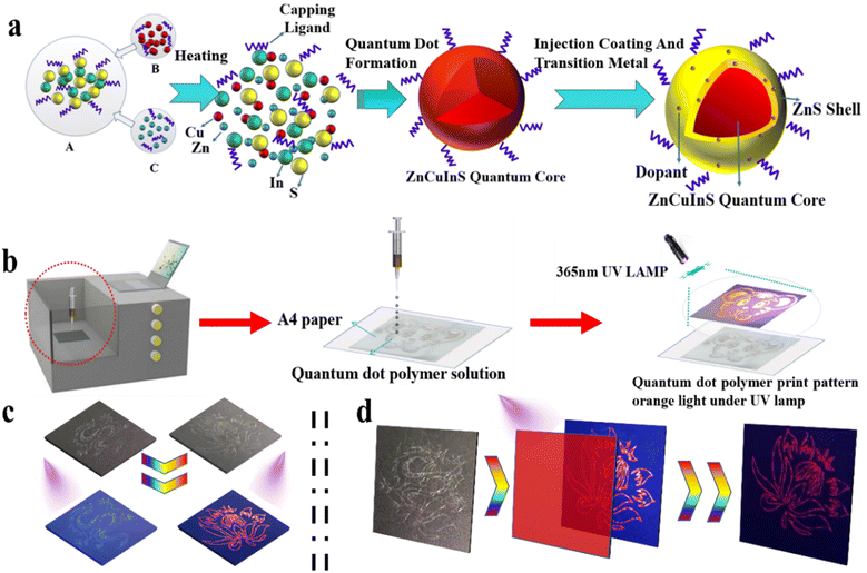
Fig. 1(a) schematically shows the synthetic stages of Mn-doped ZCIS QDs. First, ZCIS QDs were obtained by thermal injection method, followed by the formation of ZnS shell doped with Mn ions. Fig. 1(b) illustrates the process of printing visualization of QD-based emissive patterns. The printed pattern can store information, which cannot be recognized by the naked eye under normal light, but the emission from QDs is clearly visible under UV illumination. In case of printed multilayered multicolor images obtained using QDs emitting different colors, specific patterns can be selected and visualized using an appropriate optical filter. Fig. 1(c) illustrates the printing of single-layer monochromatic patterns. Under daylight, the patterns are colorless and invisible. However, blue dragons and red flowers can be clearly seen under UV light. Fig. 1(d) demonstrates how we printed out two different overlapping patterns that form a confused complex pattern. To obtain the right information, one needs to use an appropriate filter.3.1 Characterization of Mn-doped ZCIS QDs
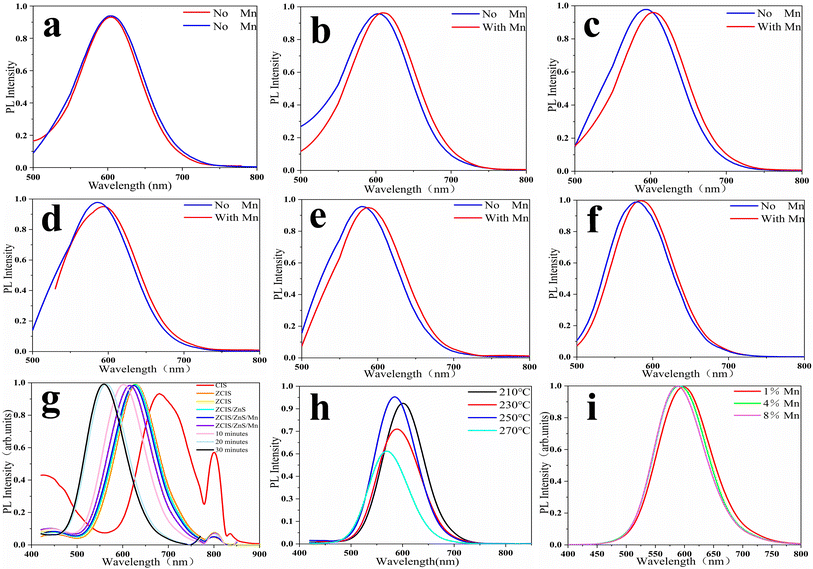
Fig. 2 shows the PL spectra of ZCIS QDs obtained at different reaction temperatures with and without Mn doping. Fig. 2(a) shows that the emission peaks of the two groups of experiments are the same with undoped Mn. Fig. 2(b–f) indicates that there is a deviation between the emission peaks of doped Mn and undoped Mn in the same time period. This proves that the doping of Mn is successful. The presence of the Mn precursor in the reaction mixture results in a weak, ca. 10 nm, red shift of the PL peaks. Increased reaction temperature causes a shift in the PL peak to the blue region, as seen from panel F due to the continuous diffusion of Zn and Mn atoms inside the CIS core and the increase in its band gap. According to the literature data, Mn-doped QDs show a characteristic PL band in the range of 580–600 nm depending on the crystalline matrix. However, in ZCIS QDs, an Mn-related PL band is strongly overlapped with the intrinsic ZCIS emission from the Cu-meditated hole trap level.29–31 Therefore, it is difficult to prove the incorporation of Mn ions into the ZCIS matrix from the PL spectra alone without involving additional analytical methods, such as XPS or EPR spectroscopy. The red and blue spectra come from two sets of experiments, respectively. Fig. 2(g) and (h) show the fluorescence spectrum of the synthesized Mn quantum dots, and it is found that the fluorescence intensity is the highest when the temperature is increased to 250 °C. As shown in Fig. 2(i), in the synthesis of the reaction mixture, Mn with different concentrations was doped. As can be seen from the figure, they are all stable at 580–600 nm.Fig. 3 demonstrates the TEM images of ZCIS, ZCIS/ZnS, and ZCIS/ZnS/Mn QDs. The corresponding size distribution histograms show a continuous growth in the size of QDs during the capping of ZCIS QDs with the ZnS shell and doping with Mn ions. The XRD pattern of ZCIS QDs points to the cubic crystalline structure, in correspondence to the reference data (JCPDS NO. 47-1370). The diffraction peaks at 2θ = 28.0, 46.5, and 55.2 degrees correspond to (111), (220), and (131) crystalline planes, respectively. The corresponding diffraction peaks for ZCIS/Mn QDs dots stay almost at the same position as that for ZCIS, which means that the doping of ZCIS QDs with Mn does not significantly affect its crystalline structure,32,33 especially if we take into account that Mn is introduced mainly into the ZnS shell. Insets in Fig. 3(a–c) shows the HETEM images of single ZCIS and ZCIS/ZnS:Mn quantum dots respectively. The interplane spacing in ZCIS QDs is 0.311 nm respectively, corresponding to (111) planes of cubic ZCIS, while for ZCIS/ZnS 0.1669 nm for (131) planes and for ZCIS/ZnS:Mn 0.194 nm for (220) planes. Taking into account corresponding XRD and the reference data we confirm that either ZnS capping or incorporation of Mn ions do not influence on the crystalline structure of ZCIS core. Calculate corresponding interplane distances for (111) (131) (220) stripes, make the same from XRD data and compare one to another with JCPDS NO. 47-1370 ± 0.01 nm. Then, make a conclusion Mn incorporation not affects the crystalline structure.
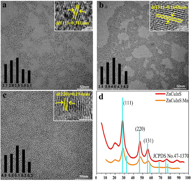 | ||
| Fig. 3 The HRTEM images of ZCIS (a), ZCIS/ZnS (b), and ZCIS/ZnS/Mn QDs (c). (d) XRD patterns for ZCIS (red) and ZCIS/ZnS/Mn (orange) QDs. | ||
As shown in Fig. 4, the presence of Mn 2p states in ZCIS/Mn QDs at 641.7 eV and 653.2 eV was confirmed by XPS analysis. The observed binding energy of Mn 2p state is close to that reported earlier for Mn2+-doped ZnS and ZnSe QDs,34 confirming that the Mn is in the 2+ state. The XPS spectrum at the Cu 2p range consists of two peaks, 2p3/2 (931.25 eV) and 2p1/2 (951.2 eV), pointing to the +1 valent state of Cu. The doping of Mn2+ does not affect the binding energy of the Zn 2p state with two peaks at 1020.8 eV (2p3/2) and 1043.7 eV (2p1/2). The binding energies for In 3d3+ and S 2p2− states slightly increases after doping with Mn, perhaps due to the partial substitution of In with Mn and crystalline lattice compression (Fig. 3(d)). The EPR spectra of ZCIS/Mn QDs further confirms that Mn2+ ions are introduced into the ZCIS matrix.7,35–38 Hyperfine splitting related to the coupling of the electron spin and the 5/2 nuclear spin of Mn2+ ions is not well resolved, perhaps due to the electron spin–spin interaction of Mn2+ ions or variable crystal environment in quaternary ZCIS QDs. Nevertheless, the estimated hyperfine constant shows that most Mn2+ ions are located inside the ZCIS QD tetragonal lattice and not on the surface.
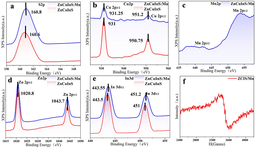 | ||
| Fig. 4 The XPS spectra of ZCIS and ZCIS/Mn QDs at S, Cu, Mn, Zn, and In spectral range (a–e) and EPR spectrum of ZCIS/Mn QDs (f). | ||
The EDS spectra of ZCIS and ZCIS/Mn QDs presented in Fig. 5(a) and (b) confirm the presence of Zn, Cu, In, and S in the synthesized QDs. The EDS spectrum in Fig. 5(b) demonstrates a strong increase in Zn due to the formation of ZnS on the surface of ZCIS QDs and a weak signal from Mn, showing that Mn doping is carried out at the same time as ZnS capping. The corresponding STEM-EDS elemental mapping of ZCIS/Mn QDs in Fig. 5(c) demonstrates the spatial distribution of Zn, Cu, In, S, and Mn atoms in the sample showing that indeed Mn location coincides with Zn, Cu, In, and S atoms.
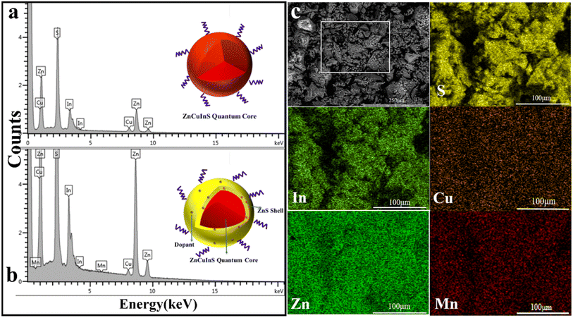 | ||
| Fig. 5 The EDS spectra of ZCIS (a) and ZCIS/Mn (b) QDs. (c) The STEM image (gray) and false-color STEM-EDS elemental maps for S, In, Cu, Zn, and Mn of ZCIS/Mn QDs. | ||
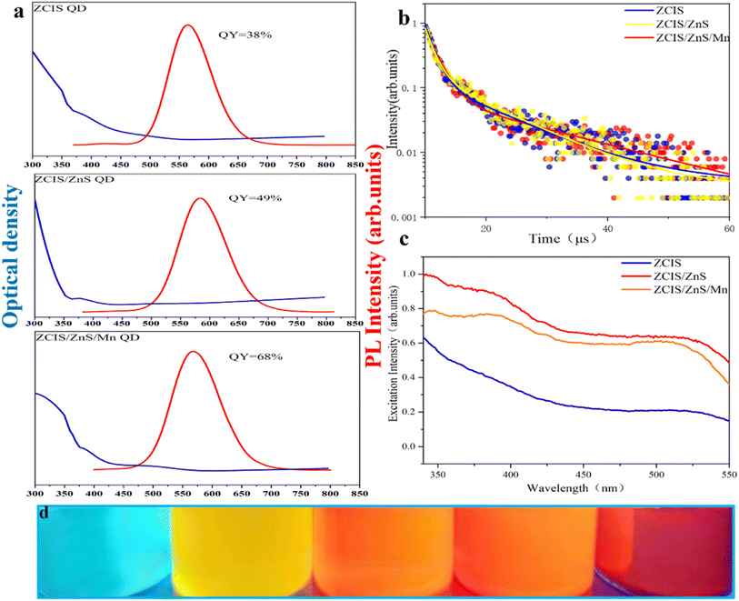
Fig. 6(a) compares the optical properties of ZCIS, ZCIS/ZnS, and ZCIS/ZnS/Mn QDs, while the absorption spectra have featureless PL bands demonstrating a weak red shift to λ ≈ 595 nm after the formation of the ZnS shell due to the dielectric confinement effect. The doping of the ZnS shell with Mn causes a reversal effect due to contribution from the Mn d–d emission normally located at about λ = 585 nm. The PL quantum yield rises from 38% for ZCIS to 49 and 68% for ZCIS/ZnS and ZCIS/ZnS:Mn QDs, demonstrating the elimination of the surface defects. PL decay curves in Fig. 6(b) possess multiexponential character with the average decay time between 9 and 12 ms practically invariable of the QDs chemical composition. The PL excitation spectra in Fig. 6(c) generally follow the trends in corresponding absorption spectra with a slight blue shift in the first absorption band after doping QDs with Mn. Fig. 6(d) shows photographic images of ZCIS, ZCIS/ZnS, and ZCIS/ZnS/Mn QDs under UV light, demonstrating the ability to vary the emission color from yellow to red with the chemical composition of QDs (additional blue-emitting sample contains ZnS QDs). With the change in the heating temperature and heating time, yellow and red quantum dots can be obtained. Mn was doped to obtain orange-yellow quantum dots.
3.2 Storage and recognition of hidden optical information with QDs
Fig. 7(a) The emission spectra of three selected colloids in trichloroethylene. The emission peak of ZCIS (red) was located at about λ = 635 nm, ZCIS (yellow) at λ = 555 nm, and ZnS (blue) at λ = 400 nm. The CIE coordinates of corresponding QDs are shown in Fig. 7(b): (x, 0.6405, y, 0.3365) for red, (x, 0.4734, y, 0.4697) for yellow, and (x, 0.1971, y, 0.1495) for blue emission. Multicolor emission can be obtained by the appropriate mixing of individual colloids. Fig. 7(c) shows the PL spectrum of white emitting colloids by carefully adjusting the ratio of blue, yellow, and red-emitting QDs in a mixture. Multicolor emitting QDs can be introduced into appropriate polymer solutions suitable for inkjet printing different color patterns. The cross pattern hides information and enhances the reliability and security of information reading.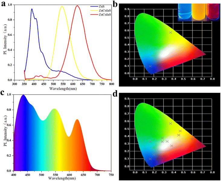 | ||
| Fig. 7 (a) The spectral map of ZCIS (red), ZCIS (yellow), ZnS (blue) PL, (b) tricolor CIE coordinates, (c) white PL spectrum, and (d) multicolor CIE coordinates. | ||
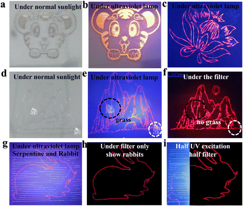
Fig. 8 demonstrates and the example printed pattern under daylight (a) and UV (365 nm) illumination. Fig. 8(c) is a pattern hidden in this position, which is normally invisible and can only be displayed if it is identified with the corresponding filter. Panels (d) through (i) in Fig. 8 demonstrate how a red-emitting pattern can be hidden with blue-emitting background and recognized with a corresponding red band-pass filter. The red band-pass filter can be used also for the selective excitation of ZCIS QDs-built pattern due to their extended PL excitation in yellow and red part of the spectrum (Fig. 8(g–i)). Fig. 8(g) and (h) show a mixed pattern of a serpentine line and a rabbit. After passing through the red filter, only the rabbit pattern is displayed. The same goes for Fig. 8(f).
4 Conclusion
We successfully prepared ZCIS QDs, carrying additional ZnS doped with Mn ions with improved PL quantum yield and variable color of emission from yellow to red. With QDs of different emission color and inkjet printing, we prepared multicolored emission patterns with hidden optical information under strong blue emission background from ZnS quantum dot QDs. The hidden emission patterns can be recognized with an appropriate band-pass optical filter.Conflicts of interest
There are no conflicts to declare.Acknowledgements
This work was supported by (1) State Key Project of International Cooperation Research (2016YFE0110800, 2017YFE0108300); (2) the National Program for Introducing Talents of Discipline to Universities (“111” plan); (3) High-End Foreign Talent Project; (4) Double Hundred Foreign Expert Project of Shandong, China; (5) High Level Discipline Program of Materials Science of Shandong Province, China; (6) M.A. acknowledges financial support the CHEMREAGENT program #2.1.04.01 (Ministry of education of the Republic of Belarus).References
- O. S. Magaña-Loaiza and R. W. Boyd, Quantum imaging and information, Rep. Prog. Phys., 2019, 82(12), 124401 CrossRef.
- Y. Song, M. Wang, S. Akkineni, W. Yang, J. J. Hettige, H. Jin, Z. Liao, P. Mu, F. Yan and M. Baer, Highly bright and photostable two-dimensional nanomaterials assembled from sequence-defined peptoids, ACS Mater. Lett., 2021, 3(4), 420–427 CrossRef CAS.
- S. Ithurria, G. Bousquet and B. Dubertret, Continuous transition from 3D to 1D confinement observed during the formation of CdSe nanoplatelets, J. Am. Chem. Soc., 2011, 133(9), 3070–3077 CrossRef CAS.
- B. T. Diroll, D. V. Talapin and R. D. Schaller, Violet-to-blue gain and lasing from colloidal CdS nanoplatelets: low-threshold stimulated emission despite low photoluminescence quantum yield, Acs Photonics, 2017, 4(3), 576–583 CrossRef CAS.
- H. Zhang, B. H. Savitzky, J. Yang, J. T. Newman, K. A. Perez, B.-R. Hyun, L. F. Kourkoutis, T. Hanrath and F. W. Wise, Colloidal synthesis of PbS and PbS/CdS nanosheets using acetate-free precursors, Chem. Mater., 2016, 28(1), 127–134 CrossRef CAS.
- G. Motomura, T. Uematsu, S. Kuwabata, T. Kameyama, T. Torimoto and T. Tsuzuki, Quantum-Dot Light-Emitting Diodes Exhibiting Narrow-Spectrum Green Electroluminescence by Using Ag–In–Ga–S/GaSx Quantum Dots, ACS Appl. Mater. Interfaces, 2023, 15(6), 8336–8344 CrossRef CAS.
- H. C. Yoon, J. H. Oh, M. Ko, H. Yoo and Y. R. Do, Synthesis and characterization of green Zn–Ag–In–S and red Zn–Cu–In–S quantum dots for ultrahigh color quality of down-converted white LEDs, ACS Appl. Mater. Interfaces, 2015, 7(13), 7342–7350 CrossRef CAS.
- L. He, S. Mei, Q. Chen, W. Zhang, J. Zhang, J. Zhu, G. Chen and R. Guo, Two-step synthesis of highly emissive C/ZnO hybridized quantum dots with a broad visible photoluminescence, Appl. Surf. Sci., 2016, 364, 710–717 CrossRef CAS.
- X. Yuan, J. Hua, R. Zeng, D. Zhu, W. Ji, P. Jing, X. Meng, J. Zhao and H. Li, Efficient white light emitting diodes based on Cu-doped ZnInS/ZnS core/shell quantum dots, Nanotechnology, 2014, 25(43), 435202 CrossRef.
- J. Park and S.-W. Kim, CuInS 2/ZnS core/shell quantum dots by cation exchange and their blue-shifted photoluminescence, J. Mater. Chem., 2011, 21(11), 3745–3750 RSC.
- N. Zikalala, S. Parani, N. Tsolekile and O. S. Oluwafemi, Facile green synthesis of ZnInS quantum dots: temporal evolution of their optical properties and cell viability against normal and cancerous cells, J. Mater. Chem. C, 2020, 8(27), 9329–9336 RSC.
- L. Li, T. J. Daou, I. Texier, T. T. Kim Chi, N. Q. Liem and P. Reiss, Highly luminescent CuInS2/ZnS core/shell nanocrystals: cadmium-free quantum dots for in vivo imaging, Chem. Mater., 2009, 21(12), 2422–2429 CrossRef CAS.
- Y. Hamanaka, T. Ogawa, M. Tsuzuki and T. Kuzuya, Photoluminescence properties and its origin of AgInS2 quantum dots with chalcopyrite structure, J. Phys. Chem. C, 2011, 115(5), 1786–1792 CrossRef CAS.
- J. Zhu, S. Mei, W. Yang, G. Zhang, Q. Chen, W. Zhang and R. Guo, Tunable emission of Cu (Mn)-doped ZnInS quantum dots via dopant interaction, J. Colloid Interface Sci., 2017, 506, 27–35 CrossRef CAS.
- W.-J. Zhang, C.-Y. Pan, F. Cao, H. Wang, Q. Wu and X. Yang, Synthesis and electroluminescence of novel white fluorescence quantum dots based on a Zn–Ga–S host, Chem. Commun., 2019, 55(94), 14206–14209 RSC.
- W.-J. Zhang, C.-Y. Pan, F. Cao, H. Wang and X. Yang, Bright violet-to-aqua-emitting cadmium-free Ag-doped Zn–Ga–S quantum dots with high stability, Chem. Commun., 2018, 54(33), 4176–4179 RSC.
- J. Choi, S. Yoon, F. S. Kim and N. Kim, Aqueous-phase synthesis and color-tuning of core/shell/shell inorganic nanocrystals consisting of ZnSe,(Cu, Mn)-doped ZnS, and ZnS, J. Alloys Compd., 2016, 671, 360–365 CrossRef CAS.
- R. Zeng, R. Shen, Y. Zhao, X. Li, Z. Sun and Y. Shen, Aqueous synthesis of Cu-doped ZnCdS/ZnS core/shell nanocrystals with a new and highly reactive sulfur source, Nanotechnology, 2014, 25(13), 135602 CrossRef.
- J.-J. Zheng, S. Cao, F.-M. Gao, G.-D. Wei, L. Jia and W.-Y. Yang, Synthesis of effective and qualified Cu-doped ZnSe quantum dots and their optical properties, J. Inorg. Mater., 2013, 28(2), 159–164 CrossRef CAS.
- J. Zhang, Q. Chen, W. Zhang, S. Mei, L. He, J. Zhu, G. Chen and R. Guo, Microwave-assisted aqueous synthesis of transition metal ions doped ZnSe/ZnS core/shell quantum dots with tunable white-light emission, Appl. Surf. Sci., 2015, 351, 655–661 CrossRef CAS.
- E. Sotelo-Gonzalez, L. Roces, S. Garcia-Granda, M. T. Fernandez-Arguelles, J. M. Costa-Fernandez and A. Sanz-Medel, Influence of Mn 2+ concentration on Mn 2+-doped ZnS quantum dot synthesis: evaluation of the structural and photoluminescent properties, Nanoscale, 2013, 5(19), 9156–9161 RSC.
- S. Jana, B. B. Srivastava and N. Pradhan, Correlation of dopant states and host bandgap in dual-doped semiconductor nanocrystals, J. Phys. Chem. Lett., 2011, 2(14), 1747–1752 CrossRef CAS.
- R. Begum and A. Chattopadhyay, Redox-tuned three-color emission in double (Mn and Cu) doped zinc sulfide quantum dots, J. Phys. Chem. Lett., 2014, 5(1), 126–130 CrossRef CAS.
- Q. A. Akkerman, A. Genovese, C. George, M. Prato, I. Moreels, A. Casu, S. Marras, A. Curcio, A. Scarpellini and T. Pellegrino, From binary Cu2S to ternary Cu–In–S and quaternary Cu–In–Zn–S nanocrystals with tunable composition via partial cation exchange, ACS Nano, 2015, 9(1), 521–531 CrossRef CAS.
- X. Wang, Z. Liang, X. Xu, N. Wang, J. Fang, J. Wang and G. Xu, A high efficient photoluminescence Zn–Cu–In–S/ZnS quantum dots with long lifetime, J. Alloys Compd., 2015, 640, 134–140 CrossRef CAS.
- Y. Zheng, B. Sadeghimakki, J. A. Brunning, E. M. Piano and S. Sivoththaman, Emission and Decay Lifetime Tunability in Less-Toxic Quaternary ZnCuInS Quantum Dots, IEEE Trans. Nanotechnol., 2021, 20, 525–533 CAS.
- Y. Lu, Synthesis of Colloidal Nanocrystal Heterostructures for High-Efficiency Light Emission, MPhil thesis, West Virginia University, 2014 Search PubMed.
- S. E. Irvine, T. Staudt, E. Rittweger, J. Engelhardt and S. W. Hell, Direct light-driven modulation of luminescence from Mn-doped ZnSe quantum dots, Angew. Chem., 2008, 120(14), 2725–2728 CrossRef.
- S. Cao, W. Ji, J. Zhao, W. Yang, C. Li and J. Zheng, Color-tunable photoluminescence of Cu-doped Zn–In–Se quantum dots and their electroluminescence properties, J. Mater. Chem. C, 2016, 4(3), 581–588 RSC.
- Z. Zhang, D. Liu, D. Li, K. Huang, Y. Zhang, Z. Shi, R. Xie, M.-Y. Han, Y. Wang and W. Yang, Dual emissive Cu: InP/ZnS/InP/ZnS nanocrystals: single-source “greener” emitters with flexibly tunable emission from visible to near-infrared and their application in white light-emitting diodes, Chem. Mater., 2015, 27(4), 1405–1411 CrossRef CAS.
- J. Ke, X. Li, Q. Zhao, Y. Shi and G. Chen, A novel approach to synthesize ultrasmall Cu doped Zn–In–Se nanocrystal emitters in a colloidal system, Nanoscale, 2014, 6(6), 3403–3409 RSC.
- J.-H. Kim, K.-H. Kim, S.-Y. Yoon, Y. Kim, S.-H. Lee, H.-S. Kim and H. Yang, Tunable emission of bluish Zn–Cu–Ga–S quantum dots by Mn doping and their electroluminescence, ACS Appl. Mater. Interfaces, 2019, 11(8), 8250–8257 CrossRef CAS.
- L. Dong, Z. Chen, L. Ye, Y. Yu, J. Zhang, H. Liu and J. Zang, Gram-scale synthesis of all-inorganic perovskite quantum dots with high Mn substitution ratio and enhanced dual-color emission, Nano Res., 2019, 12, 1733–1738 CrossRef CAS.
- A. Aboulaich, M. Geszke, L. Balan, J. Ghanbaja, G. Medjahdi and R. Schneider, Water-based route to colloidal Mn-doped ZnSe and core/shell ZnSe/ZnS quantum dots, Inorg. Chem., 2010, 49(23), 10940–10948 CrossRef CAS.
- L. Dai, Synthesis of Colloidal Zinc Chalcogenide Nanoplatelets: Structural and Optical Properties and Their Change upon Doping and Shell Formation, PhD thesis, Staats-und Universitätsbibliothek Hamburg Carl von Ossietzky, 2021 Search PubMed.
- Z. Quan, Z. Wang, P. Yang, J. Lin and J. Fang, Synthesis and characterization of high-quality ZnS, ZnS: Mn2+, and ZnS: Mn2+/ZnS (core/shell) luminescent nanocrystals, Inorg. Chem., 2007, 46(4), 1354–1360 CrossRef CAS.
- G. Manna, S. Jana, R. Bose and N. Pradhan, Mn-doped multinary CIZS and AIZS nanocrystals, J. Phys. Chem. Lett., 2012, 3(18), 2528–2534 CrossRef CAS.
- Q. Liu, R. Deng, X. Ji and D. Pan, Alloyed Mn–Cu–In–S nanocrystals: a new type of diluted magnetic semiconductor quantum dots, Nanotechnology, 2012, 23(25), 255706 CrossRef.
| This journal is © The Royal Society of Chemistry 2023 |

