 Open Access Article
Creative Commons Attribution 3.0 Unported Licence
Fabrication and photoelectric conversion of densely packed C60–ethylenediamine adduct microparticle films-modified electrode covered with electrochemically deposited polythiophene thin-films†
Shoto Banya a,
Yu Kumagawaa,
Daisuke Izumotoa,
Moyu Tanakaa,
Kengo Kanbe
 b,
Takeo Oku
 c and
Tsuyoshi Akiyama
 *c
*c
aDivision of Materials Science, Graduate School of Engineering, The University of Shiga Prefecture, 2500, Hassaka, Hikone, Shiga 522-8533, Japan
bDivision of Advanced Engineering Science, Graduate School of Engineering, The University of Shiga Prefecture, 2500, Hassaka, Hikone, Shiga 522-8533, Japan
cDepartment of Materials Chemistry, School of Engineering, The University of Shiga Prefecture, Hikone, Shiga 522-8533, Japan. E-mail: akiyama.t@mat.usp.ac.jp
First published on 25th October 2023
Abstract
Polythiophene-modified densely packed C60–ethylenediamine adduct microparticle films were prepared using a combination of liquid–liquid interfacial precipitation of the adduct microparticles and electrochemical polymerization of 2,2′-bithiophene. The amount of polythiophene was varied as a function of scanning cycles of the applied potential during electrochemical polymerization. Fluorescence-emission properties of these composite films suggested the role of C60–ethylenediamine adduct microparticle film as a photosensitizer in addition to an electron acceptor for polythiophene. Furthermore, cathodic photocurrents were generated via excitation of C60–ethylenediamine adduct microparticle film and polythiophenes using the half-photocell properties of the electrode modified with composite film in the presence of methylviologen.
Introduction
Fullerenes are well known sphere-shaped π-electron molecules,1–3 which have been receiving attention in the molecular based photoelectrochemical systems and organic-electronic devices owing to their electron acceptor and/or n-type semiconductor properties. In these applications, chemical modification of fullerenes is essentially important to obtain fullerene derivatives with adequate properties, such as redox potential, band structure, and solubility. One of the simplest methods used for the chemical modification of fullerenes is the addition reaction of alkylamines.4–6 Literature suggests the production of fullerene–diamine adducts via the addition reaction of C60 fullerene with a series of aliphatic diamines.7,8 Our research group has developed the fullerene–diamine adducts and evaluated their applications in photoelectric conversion.9 In preliminary studies, we reported the formation of sphere-shaped C60–aliphaticdiamine and rhombicdodecahedral-shaped C70–aliphaticdiamine adduct microparticles through simple mixing of individual solutions of fullerenes and diamines.10,11 The addition reaction of fullerenes and diamines is a key reaction to form these fullerene–diamine adduct microparticles, which has been suggested by elemental analysis, absorption spectra, infrared spectra, and X-ray diffraction patterns of corresponding adduct microparticles.10–13 These examples are interesting from a viewpoint of relationship to formation of unique anisotropic-shaped aggregates and/or assemblies of fullerenes or fullerene derivatives.14–17C60–ethylenediamine adduct microparticles (C60P) can be prepared by simply mixing a toluene solution of C60 and another toluene solution of ethylenediamine at room temperature under usual atmosphere, which seems to be easy to scale up.10,12,13,18 C60P seems to consist of secondary microparticles composed of 2–3 nm-sized C60 and ethylenediamine adduct composite.13 C60P contains a residual amino group due to ethylenediamine.12 C60P function as electron acceptor for photoexciting donor molecules, such as polythiophene and porphyrin, owing to the photocurrent-generation and fluorescence-quenching properties of the composite films of C60P and polythiophene or porphyrin formed on electrodes.18–20 In addition, C60P or densely packed C60P film (C60PF) formed at liquid–liquid interface (liquid–liquid interfacial precipitation, LLIP),19,21–24 may work as photoexciting moiety because of the photocurrent-generation properties of the half-photocell containing C60PF on an electrode.19
Electrochemical polymerization is a widely used approach for the preparation of a conductive polymer thin-film on the electrode surface via electrolysis of an electrolyte-solution containing corresponding monomer molecule.25 The resultant conductive polymer thin-film is insoluble in the electrolyte solution. The amount of deposited polymer can be controlled by optimising the operating conditions of electrolysis during electrochemical polymerization. In addition, an electrochemically polymerized thin-film can be synthesized on electrodes of various shapes. Photovoltaic application is one of the common applications where electrochemically polymerised polythiophenes are used.26–30 Our research group investigated the preparation and photoelectric conversion of electrochemically polymerized polythiophene thin-films.26,31–33 Recently, a hierarchical double-layered polythiophene thin-films was synthesized using sequential electrochemical polymerization of corresponding 3,4-ethylenedioxythiophene and 2,2′-bithiophene monomers.34–36 In particular, the effect of the thickness of outer polybithiophene thin-film as photoexciting donor on the photoelectric conversion was investigated by controlling the electrochemical thickness of polybithiophene thin-films using their half-photocell properties.35,36 Such wet-type photoelectric conversion system is also interesting, as it is correlated with bio-inspired photoelectric conversion systems.37–39
Therefore, a systematic investigation of the photoelectrochemical properties of C60PF combined with polythiophene is crucial. Herein, a series of electrodeposited polybithiophene-modified C60PF/indium–tin-oxide (ITO) electrodes were fabricated and evaluated. The amount of polybithiophene was varied as a function of scanning cycles of applied potentials during electrochemical polymerization. The fluorescence-emission and photocurrent-generation properties of the modified electrodes were evaluated, and the role of C60P in C60PF was discussed.
Experimental
All chemicals were commercially obtained and used as-received. Ultrapure water (18.2 M cm) was used in the experiments. A schematic of the fabrication procedure of polybithiophene-modified C60P film on an ITO electrode is shown in Fig. 1. The C60P and C60PF were synthesized as reported previously.19 To prepare C60P, individual solutions of C60 (2.0 mM, 144 mg/100 mL) and ethylenediamine (2.0 M, 13.4 mL/100 mL) were prepared in toluene and mixed for 1 min under sonication at room temperature, followed by continuous stirring for 20 h at room temperature. The resultant submicrometer-sized particles of C60P were collected after centrifugation (6000 rpm, 30 min) and dried in vacuum to obtain C60P as a brown powder. An ITO-coated glass substrate (ITO, Geomatec 0002, with a sheet resistance of ca. 10 Ω per square) was used as a transparent electrode. The substrate was washed using acetone and methanol in each sequence for 10 min under ultrasonic treatment and dried using nitrogen gas. Subsequently, the ITO electrode was cleaned in an ozone atmosphere (using UV ozone cleaner) for 15 min. The pre-cleaned ITO substrate was immersed in an aqueous solution of 1.5 mM polyethyleneimine (PEI, MW: 750![[thin space (1/6-em)]](https://www.rsc.org/images/entities/char_2009.gif) 000) for 30 min at room temperature, followed by washing with ultrapure water to modify the PEI on the ITO surface, denoted as PEI/ITO. The PEI/ITO substrate was immersed in an aqueous solution of 0.5 mM poly(styrene sulfonate) (PSS, MW: 70
000) for 30 min at room temperature, followed by washing with ultrapure water to modify the PEI on the ITO surface, denoted as PEI/ITO. The PEI/ITO substrate was immersed in an aqueous solution of 0.5 mM poly(styrene sulfonate) (PSS, MW: 70![[thin space (1/6-em)]](https://www.rsc.org/images/entities/char_2009.gif) 000) for 30 min at room temperature, followed by washing with ultrapure water to modify PSS on the PEI/ITO surface, denoted as PSS/PEI/ITO.40,41 The PSS/PEI/ITO was stored in ultrapure water at room temperature for subsequent use.
000) for 30 min at room temperature, followed by washing with ultrapure water to modify PSS on the PEI/ITO surface, denoted as PSS/PEI/ITO.40,41 The PSS/PEI/ITO was stored in ultrapure water at room temperature for subsequent use.
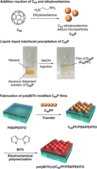 | ||
| Fig. 1 Fabrication of polybithiophene electrochemically polymerized thin-film modified densely packed C60–ethylenediamine adduct microparticles film. | ||
The C60P film is prepared by LLIP method as follows: a liquid–liquid interface using a 0.2 mg mL−1 aqueous dispersed solution of C60P (15 mL) and hexane (10 mL) was prepared in a vial (ϕ = 30 mm, volume: 50 mL). Immediately after, methanol (15 mL) as aggregation inducer of C60P, was injected into the solution vigorously, resulting in an instantaneous change in the color of the aqueous phase from brown to colorless. Simultaneously, a liquid-like film of C60Ps forms at the hexane–water interface. The resultant C60PF was manually transferred onto the surface of the PSS/PEI/ITO by vertical lifting to obtain C60PF on ITO electrode denoted as C60PF/PSS/PEI/ITO or polyBiTh(n)/C60PF/PSS/PEI/ITO (n = 0).
The C60PF/PSS/PEI/ITO, a nickel plate, and silver wire were used as a working, counter, and reference electrodes, respectively, in a three-electrode electrochemical cell containing 1.0 mM 2,2′-bithiophene (BiTh), and 0.1 M nBu4NPF6 in CH2Cl2. The distance between working and counter electrodes is fixed at 5 mm. Immersed dimension of the working electrode in an electrolyte solution is 2 cm × 1.5–1.8 cm. The applied potential to the working electrode was scanned between 0 and +2 V (initial potential 0 V, switching potential +2 V and final potential 0 V) vs. silver wire for n times at a speed of 0.05 V s−1 using the cyclic voltammetry (CV) method of a potentiostat (ALS, model 650C), where n is the number of sweeping potentials. During electrochemical polymerization, the electrolyte solution was stirred at a speed of 400 rpm. After electrochemical polymerization, the working electrode was removed from the electrolyte solution followed by rinsing with enough amount of CH2Cl2 and drying in air to obtain the polybithiophene (polyBiTh)-modified C60PF on ITO electrode, denoted as polyBiTh(n)/C60PF/PSS/PEI/ITO (n = 1, 3, 5, 13, 20, and 40 cycles). The polyBiTh-modified PSS/PEI/ITO electrodes without C60PF were also prepared using same polymerization condition of BiTh, white are denoted as polyBiTh(n)/PSS/PEI/ITO (n = 1, 3, 5, 13, 20, and 40 cycles).
Transparent Ultraviolet-Visible-Near Infrared (UV-vis-NIR) spectra of the polyBiTh(n)/C60PF/PSS/PEI/ITO were recorded on Jasco V-670 UV-vis-NIR spectrometer to investigate their optical properties. Fluorescence spectra of the polyBiTh(n)/C60PF/PSS/PEI/ITO were measured using Jasco FP-6600. Excitation light was irradiated on polyBiTh side at an incident angle of 45° and fluorescence emission was measured at an exit angle of 45°. Scanning electron micrographs (SEM) for the polyBiTh(n)/C60PF/PSS/PEI/ITO were recorded using a Hitachi S-4500 scanning electron microscope. Photocurrent measurements were carried out in a three-electrode photoelectrochemical cell using a potentiostat (Huso, HECS 318C) and a monochromatic light from a 150 W xenon lamp (Bunko Keiki, SM-25). The polyBiTh(n)/C60PF/PSS/PEI/ITO (n = 0–40 cycles), an Ag/AgCl (sat. KCl), and a platinum wire were used as working, reference, and counter electrodes, respectively. The aqueous solution containing 0.1 M sodium perchlorate and 1.0 mM 1,1′-dimethyl-4,4′-bipyridinium dichloride hydrate (methylviologen, MV2+) as electron acceptors was employed as an electrolyte. Photocurrents were measured at an applied potential of E = 0 or −0.2 V vs. Ag/AgCl (sat. KCl) for the working electrode. The monochromatic light was irradiated to the working electrode. The irradiated area of the working electrode was adjusted to be 0.38 cm2. The incident photon-to-current conversion efficiency (IPCE) of the photocurrent was evaluated at the given absorbance using the following eqn (1).
 | (1) |
Results and discussion
Fig. 2 shows a cyclic voltammogram obtained during the electrochemical polymerization of polyBiTh on C60PF/PSS/PEI/ITO to prepare polyBiTh(20)/C60PF/PSS/PEI/ITO. The values of oxidation and reduction current increase with increasing number of scanning cycles (n) of applied potential, indicating the formation of polyBiTh via electrochemical oxidation of BiTh on C60PF/PSS/PEI/ITO followed by re-reduction. Furthermore, essentially similar behavior is also observed in all polyBiTh(n)/C60PF/PSS/PEI/ITO (n = 1–40 cycles), as shown in Fig. S1.† These voltammetric characteristics of the polyBiTh(n)/C60PF/PSS/PEI/ITO are essentially similar to that of polyBiTh film prepared using electrochemical polymerization of BiTh on a bare electrode (Fig. S2†). Moreover, no obvious changes in the current profile of C60PF/PSS/PEI/ITO (Fig. S3†) were observed in the cyclic voltammogram when a potential sweep is applied in the 0.1 M nBu4NPF6 in CH2Cl2 without BiTh, indicating the stability of C60PF during electrochemical preparation of polyBiTh.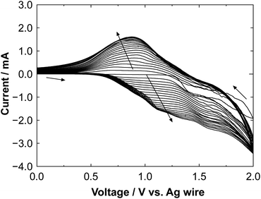 | ||
| Fig. 2 Cyclic voltammogram of the electrochemical polymerization of polyBiTh on C60PF/PSS/PEI/ITO during preparation of polyBiTh(20)/C60PF/PSS/PEI/ITO. | ||
Photographs of polyBiTh(n)/C60PF/PSS/PEI/ITO (n = 0, 3, 5, 13, 20, and 40 cycles) is shown in Fig. 3. A light brown colored layer is observed in the C60PF/PSS/PEI/ITO. After electrochemical polymerization, the color of the adsorbed films changes slightly. In addition, the color of the films becomes darker with increasing n at the given applied potential, suggesting an increase in the adsorbed amount of polyBiTh with increasing n. In the case of polyBiTh(n)/PSS/PEI/ITO without C60PF, similar change tendency of the color of the films is observed (Fig. S4†).
Relative Raman scattering spectra of polyBiTh(n)/C60PF/PSS/PEI/ITO are shown in Fig. 4. The spectra were obtained after baseline correction of Raman scattering spectra as measured (Fig. S5†). In Fig. 4, positions of each baseline were adjusted for comparison, and relative intensities of Raman signals were not adjusted. The characteristic Raman scattering signals are observed at a Raman shift of 1045, 1455, 2500, and 2905 cm−1 after the electrochemical modification of polyBiTh rather than the broad Raman scattering signal of C60PF/PSS/PEI/ITO at 1410 and 1590 cm−1. These results suggest the formation of polyBiTh on C60PF/PSS/PEI/ITO via electrochemical polymerization.
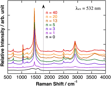 | ||
| Fig. 4 Relative Raman scattering spectra of polyBiTh(n)/C60PF/PSS/PEI/ITO, after baseline correction and adjusted for comparison. Relative intensities of Raman signals were not adjusted. | ||
Fig. 5(a) and S6(a)† show the SEM images of polyBiTh(n)/C60PF/PSS/PEI/ITO (n = 1, 3, 5, 13, 20, and 40 cycles). Sphere-shaped structures with diameters of 350–500 nm are observed, which can be attributed to C60P. An approximate evaluation of the diameters of C60P present in the polyBiTh(n)/C60PF/PSS/PEI/ITO indicates an increase in the diameters of C60P with increasing n, thereby suggesting the adsorption of polyBiTh on the entire surface of C60P present in C60PF/PSS/PEI/ITO. In addition, structures of a few tens to 100 nm size are observed at all values of n except n = 1. The growth of these microstructures is non-uniform on polyBiTh, which can be attributed to the considerably small protuberance of the concentration of electric field on C60P or polyBiTh and resultant acceleration of electrochemical polymerization of BiTh at the site. This is supported by the cross-sectional SEM images of polyBiTh(n)/C60PF/PSS/PEI/ITO, which are shown in Fig. S6(b).†
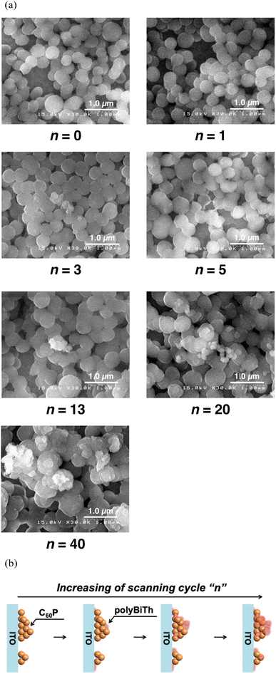 | ||
| Fig. 5 (a) SEM images of polyBiTh(n)/C60PF/PSS/PEI/ITO (n = 0, 1, 3, 5, 13, 20, and 40 cycles), and (b) proposed mechanism of polyBiTh thin-films growing on C60PF/PSS/PEI/ITO. | ||
Thus, the suggested mechanism can be a combination of the following: (1) uniform formation of polyBiTh thin-film on the C60P surface, and (2) non-uniform formation of polyBiTh structures of a few tens to 100 nm size, which is shown in Fig. 5(b).
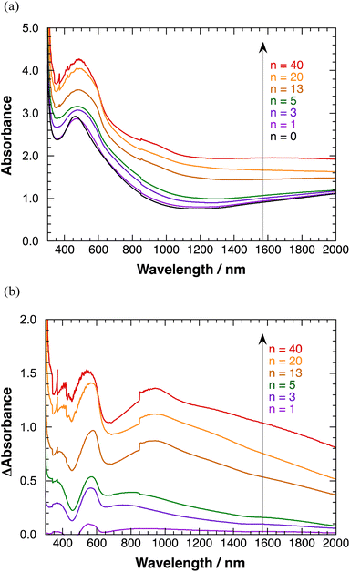
Transparent absorption spectra of polyBiTh(n)/C60PF/PSS/PEI/ITO are shown in Fig. 6(a). Discontinuous steps in the absorption spectra were observed at 850 nm, which correspond to the switching wavelength during spectral measurements. These obvious spectral steps may be due to the significant effect of 350 nm-sized C60Ps in C60PF on the light path. A broad absorption band at a peak wavelength of 460 nm is observed when n = 0 (C60PF/PSS/PEI/ITO), which is attributed to C60P present in C60PF.18,19 Furthermore, the absorbance values increase for the broad absorption band at a peak wavelength of approximately 500 nm and wavelength region longer than 800 nm with increasing value of n in the range of 1–40. An increase in the baseline, which is the sum of optical absorption and geometrical scattering, with increasing n is reasonable owing to the combination of C60PF and polyBiTh. Differential absorption spectra of polyBiTh(n)/C60PF/PSS/PEI/ITO (n = 1–40 cycles) obtained after subtraction of the absorption spectrum of C60PF/PSS/PEI/ITO from corresponding absorption spectra of polyBiTh(n)/C60PF/PSS/PEI/ITO are shown in Fig. 6(b). A broad absorption band at 450–650 nm is observed in all polyBiTh-modified electrode because of the neutral state of typical polythiophene. The absorbance values increase with increasing n, suggesting an increase in the adsorbed amount of polyBiTh on C60PF/PSS/PEI/ITO with increasing n. In addition, a significantly broad NIR absorption band at a peak wavelength of approximately 850–950 nm is observed in all polyBiTh-modified electrode, which is attributed to the polaron absorption band of polythiophenes. A relatively higher absorbance of the polaron absorption band than the visible neutral absorption band of polyBiTh is observed more significantly at n = 13, 20, and 40 cycles than those at n = 1, 3, and 5 cycles. This is attributed to the residual polaron of polyBiTh during electrochemical polymerization process. Although the applied potential is set to 0 V vs. Ag wire at the end of electrochemical polymerization, some amount of polyBiTh cannot be reduced electrochemically. A relatively higher ratio of oxidized state of polyBiTh is observed in the polyBiTh film when a relatively larger amount of polyBiTh is formed at n = 13, 20, and 40 cycles than that at n = 1, 3, and 5 cycles. Corresponding absorption spectra of polyBiTh(n)/PSS/PEI/ITO without C60PF are shown in Fig. S7(a) and (b).† Characteristic absorption bands of the neutral state and polaron of the typical polythiophene are also observed. Differences of absorbance in differential absorption spectra of polyBiTh(n)/C60PF/PSS/PEI/ITO and polyBiTh(n)/PSS/PEI/ITO may be due to difference of surface morphologies at polyBiTh film forming.
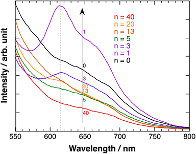
Fig. 7 shows the fluorescence emission spectra of polyBiTh(n)/C60PF/PSS/PEI/ITO exited at 450 nm. A considerably broad emission in the wavelength region of 600–700 nm with inflection points at 640 and 685 nm is observed at n = 0 (C60PF/PSS/PEI/ITO). In contrast, a decrease in the emission with increasing wavelength is observed at all other values of n. The broad emission band at 600–700 nm is attributed to the fluorescence-emission from the excited state of C60P present in the C60PF/PSS/PEI/ITO. Furthermore, two characteristic emission peaks at approximately 615 and 670 nm are observed in polyBiTh(1)/C60PF/PSS/PEI/ITO, which are attributed to the photoexcited state of neutral polythiophene.20,42 Order of emission intensity at 615 nm of polyBiTh(n)/C60PF/PSS/PEI/ITO (n = 1–40 cycles) is given as follows:
| n = 1 > 3 > 13, 20 > 5 > 40 cycles |
This order seems to be a sum of some mechanisms of increasing or decreasing of emission from excited polyBiTh, shown as follows. It is known that polaron decreases emission from excited state of polythiophene during the fluorescence-emission of polythiophene.43 The absorption spectra recorded in the present study indicates a higher effect of polaron on the polyBiTh film with a larger n than that on polyBiTh film with a smaller n. Another reason for the decreased emission can be diffusion and multiple reflections of light owing to the changes in surface morphology of polyBiTh(n)/C60PF/PSS/PEI/ITO. Furthermore, emission of polyBiTh can be enhanced by the energy transfer from photoexcited C60PF to polyBiTh. In addition, if the C60P has a refractive index similar to C60, the irradiated light may be localised in the area of several tens of nm in the proximity of C60P, thereby enhancing the excitation of C60P and polyBiTh. Thicker polyBiTh film could be formed at higher values of n. The degree of emission of polyBiTh induced by energy transfer from C60PF decreases with the increasing n. Furthermore, the degree of electron-transfer quenching, which can happen simultaneously, from the excited state of polyBiTh to C60PF,20 decreases with the increasing n. Thus, a combination of all the aforementioned mechanisms explains the order of the emission intensity of polyBiTh(n)/C60PF/PSS/PEI/ITO.
Fig. 8(a) shows the IPCE profiles for the cathodic photocurrent of polyBiTh(n)/C60PF/PSS/PEI/ITO (n = 1–40 cycles) at E = 0 V. The IPCEs of polyBiTh(n)/C60PF/PSS/PEI/ITO (n = 1, 3, 5, 13, and 20 cycles) increase with the increasing n because of the increasing contribution of the increased amount of polyBiTh. Furthermore, the IPCEs increased in the wavelength region of 400–550 nm at n = 5, 13, and 20 compared to that of polyBiTh(3)/C60PF/PSS/PEI/ITO, which is attributed to the increasing amount of polyBiTh at a distance from C60P of C60PF/PSS/PEI/ITO, and the increasing amount of excited polyBiTh that contributes in the generation of cathodic photocurrent. These IPCE profiles change can be explained as the result of a combination of the following photocurrent generation mechanisms and electron transfer reactions: (1) cathodic photocurrent generation due to the electron-transfer from excited polyBiTh to MV2+ in bulk, (2) reduction of cathodic photocurrent due to electron-transfer from excited polyBiTh to C60P of C60PF, and (3) an enhanced generation of excited polyBiTh via energy transfer from photoexcited C60P and/or light concentration around C60P (as described above). In particular, the enhanced generation of excited polyBiTh is induced by absorption of C60P of C60PF/PSS/PEI/ITO, thereby reducing the cathodic photocurrent in the wavelength region of 400–550 nm.
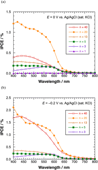 | ||
| Fig. 8 IPCE profiles of polyBiTh(n)/C60PF/PSS/PEI/ITO in the presence of methyl viologen at (a) 0 V, and (b) −0.2 V versus Ag/AgCl (sat. KCl). | ||
Moreover, the IPCEs of polyBiTh(40)/C60PF/PSS/PEI/ITO are considerably lower than that of polyBiTh(20)/C60PF/PSS/PEI/ITO due to the suppressed electron-transfer by thicker polyBiTh film of polyBiTh(40)/C60PF/PSS/PEI/ITO. Fig. 8(b) shows the IPCE profiles of polyBiTh(n)/C60PF/PSS/PEI/ITO (n = 3, 5, 13, 20, and 40 cycles) at E = −0.2 V. The IPCE values of these modified electrodes are higher than those at E = 0 V. Thus, the overall IPCE profile (except their values) for irradiation wavelength does not change at E = 0 V. However, IPCEs of polyBiTh(40)/C60PF/PSS/PEI/ITO increase significantly and become similar to that of polyBiTh(20)/C60PF/PSS/PEI/ITO. This is attributed to the decrease in polaron of polyBiTh of polyBiTh(40)/C60PF/PSS/PEI/ITO owing to more negative applied potential −0.2 V than 0 V. This results in increasing neutral moiety of polyBiTh, which may increase the cathodic photocurrent.
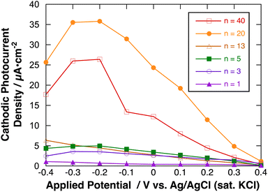
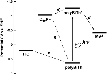
Fig. 9 shows the effect of applied potential on the photocurrent of polyBiTh(n)/C60PF/PSS/PEI/ITO (n = 1–40) under irradiation of white light from a 150 W xenon lamp with ultraviolet cut-off filter. Cathodic photocurrent increases with increasing values of the negative applied potentials in the region from 0.4 to −0.2 V. The cathodic photocurrent decreases in the region of −0.3 to −0.4 V with higher negative potentials. This may be affected by the static cathodic current of electrochemical reduction of MV2+, which cannot be ignored. The aforementioned photocurrent-generation properties suggest that the photocurrent-generation mechanism of polyBiTh(n)/C60PF/PSS/PEI/ITO is a combination of sequential reactions of electron-transfer and energy-transfers (Fig. 10).19,36
These cathodic photocurrents are generated by electron-transfer through C60P of a size of submicrometers. In general, long-range electron-transfer is difficult to take place. In fact, C60P consists of polymer or oligomer of C60–ethylenediamine adduct. The C60 moieties of C60P are considerably close to each other, thereby facilitating a smooth electron-transfer among C60Ps within C60P.
This study suggests the unique photochemical and electrochemical properties of C60P present in the C60PF/PSS/PEI/ITO based on the evaluation of their effect on polyBiTh moiety for the fluorescence and photocurrent-generation properties of the modified electrodes. A detailed photochemical analysis, including the time-resolved photochemical spectrum measurements and photoelectrochemical properties, of C60P and their derivatives is required to further illustrate the role of C60P under photoexcitation. This will be a part of our ongoing research work.
Conclusions
Composite films consisting of electrochemically polymerized polythiophene and densely packed C60–ethylenediamine adduct microparticle film were synthesized on electrodes. Fluorescence-emission and photocurrent-generation properties of these modified electrodes indicated the role of C60–ethylenediamine adduct microparticle film as photoexciting moiety in addition to an electron acceptor for polythiophene which could transfer excitation energy to polythiophene. These unique properties of C60–ethylenediamine adduct microparticle film suggested the potential applications of the synthesized film in photoelectrochemical devices, such as photoelectric conversion devices and sensors.Conflicts of interest
There are no conflicts to declare.Acknowledgements
This work was partly supported by JSPS KAKENHI Grant Numbers JP22550123 and JP16K05754.References
- E. Osawa, Kagaku, 1970, 25, 854–863 CAS.
- Z.-i. Yoshida and E. Osawa, Aromaticity, Kagaku-dojin, 1971, pp. 174–178 Search PubMed.
- H. W. Kroto, J. R. Heath, S. C. O'Brien, R. F. Curl and R. E. Smalley, Nature, 1985, 318, 162–163 CrossRef CAS.
- A. Hirsch, L. Qiaoying and F. Wudl, Angew. Chem., Int. Ed., 1991, 30, 1309–1310 CrossRef.
- H. Isobe, N. Tomita and E. Nakamura, Org. Lett., 2000, 2, 3663–3665 CrossRef CAS PubMed.
- F. Wudl, A. Hirsch, K. C. Khemani, T. Suzuki, P.-M. Allemand, A. Koch, H. Eckert, G. Srdanov and H. M. Webb, in Fullerenes, ed. G. S. Hammond and V. J. Kuch, American Chemical Society, 1992, vol. 481, pp. 161–175 Search PubMed.
- J. R. Hwu, T. Y. Kuo, T. M. Chang, H. V. Patel and K. T. Yong, Fullerene Sci. Technol., 1996, 4, 407–422 CrossRef CAS.
- A. Ulüg, A. Mete and B. Ulüg, Fullerene Sci. Technol., 1997, 5, 1651–1658 CrossRef.
- T. Akiyama, Bull. Chem. Soc. Jpn., 2019, 92, 1181–1199 CrossRef CAS.
- K.-i. Matsuoka, S. Matsumura, T. Akiyama and S. Yamada, Chem. Lett., 2008, 37, 932–933 CrossRef CAS.
- K.-i. Matsuoka, T. Akiyama and S. Yamada, Langmuir, 2010, 26, 4274–4280 CrossRef CAS PubMed.
- T. Akiyama, T. Ueda, Y. Ono, K. Kimura, K.-i. Matsuoka, S. Yamada and T. Oku, Chem. Lett., 2013, 42, 177–179 CrossRef CAS.
- T. Akiyama, Y. Ono, H. Miyamura, J. Saito, K. Kimura, S. Higashida and T. Oku, J. Nanopart. Res., 2018, 20, 252 CrossRef.
- L. K. Shrestha, Y. Yamauchi, J. P. Hill, K. i. Miyazawa and K. Ariga, J. Am. Chem. Soc., 2013, 135, 586–589 CrossRef CAS PubMed.
- P. Bairi, T. Tsuruoka, S. Acharya, Q. Ji, J. P. Hill, K. Ariga, Y. Yamauchi and L. K. Shrestha, Mater. Horiz., 2018, 5, 285–290 RSC.
- G. S. Kumar, R. G. Shrestha, Q. Ji, J. P. Hill, K. Ariga, S. Acharya and L. K. Shrestha, Phys. Chem. Chem. Phys., 2018, 20, 18873–18878 RSC.
- G. Chen, F. Sciortino, K. Takeyasu, J. Nakamura, J. P. Hill, L. K. Shrestha and K. Ariga, Chem.–Asian J., 2022, e202200756 CrossRef CAS PubMed.
- K.-i. Matsuoka, H. Seo, T. Akiyama and S. Yamada, Chem. Lett., 2007, 36, 934–935 CrossRef CAS.
- S. Banya, T. Akiyama, D. Izumoto, A. Suzuki and T. Oku, Chem. Lett., 2015, 44, 489–491 CrossRef CAS.
- T. Akiyama, S. Matsumura, K.-i. Matsuoka, T. Oku and S. Yamada, J. Phys.: Conf. Ser., 2013, 433, 012010 CrossRef CAS.
- H. S. Nalwa, A. Kakuta, A. Mukoh, H. Kasai, S. Okada, H. Oikawa, H. Nakanishi and H. Matsuda, Adv. Mater., 1993, 5, 758–760 CrossRef CAS.
- J. Matsui, T. Shibata, K. Yamamoto, T. Yokoyama, A. Masuhara, H. Kasai, H. Oikawa and T. Miyashita, Synth. Met., 2009, 159, 847–850 CrossRef CAS.
- L. K. Shrestha, J. P. Hill, T. Tsuruoka, K. i. Miyazawa and K. Ariga, Langmuir, 2013, 29, 7195–7202 CrossRef CAS PubMed.
- R. G. Shrestha, L. K. Shrestha, A. H. Khan, G. S. Kumar, S. Acharya and K. Ariga, ACS Appl. Mater. Interfaces, 2014, 6, 15597–15603 CrossRef CAS PubMed.
- J. Roncali, Chem. Rev., 1992, 92, 711–738 CrossRef CAS.
- K. Takechi, T. Shiga, T. Motohiro, T. Akiyama, S. Yamada, H. Nakayama and K. Kohama, Sol. Energy Mater. Sol. Cells, 2006, 90, 1322–1330 CrossRef CAS.
- R. Valaski, C. D. Canestraro, L. Micaroni, R. M. Q. Mello and L. S. Roman, Sol. Energy Mater. Sol. Cells, 2007, 91, 684–688 CrossRef CAS.
- J. Yan, C. Sun, F. Tan, X. Hu, P. Chen, S. Qu, S. Zhou and J. Xu, Sol. Energy Mater. Sol. Cells, 2010, 94, 390–394 CrossRef CAS.
- E. Nasybulin, J. Feinstein, M. Cox, I. Kymissis and K. Levon, Polymer, 2011, 52, 3627–3632 CrossRef CAS.
- Y. Tezuka, T. Yamamoto, Y. Kamikado and H. Tanaka, Sol. Energy Mater. Sol. Cells, 2012, 105, 167–173 CrossRef CAS.
- T. Akiyama, K. Kakutani and S. Yamada, Jpn. J. Appl. Phys., 2004, 43, 2306–2310 CrossRef CAS.
- K. Sugawa, T. Akiyama and S. Yamada, Thin Solid Films, 2008, 516, 2502–2506 CrossRef CAS.
- T. Akiyama, H. Yoneda, T. Fukuyama, K. Sugawa, S. Yamada, K. Takechi, T. Shiga, T. Motohiro, H. Nakayama and K. Kohama, Jpn. J. Appl. Phys., 2009, 48, 04C172 Search PubMed.
- Y. Kumagawa, T. Akiyama, Y. Nishimura, K. Goto, A. Suzuki and T. Oku, Bull. Chem. Soc. Jpn., 2016, 89, 700–704 CrossRef CAS.
- K. Kanbe, T. Akiyama, Y. Kumagawa, S. Hirata, T. Tsujiai and T. Oku, Jpn. J. Appl. Phys., 2022, 61, 061008 CrossRef.
- K. Kanbe, T. Akiyama and T. Oku, ECS Advances, 2023, 2, 020505 CrossRef.
- S. C. Tan, L. I. Crouch, S. Mahajan, M. R. Jones and M. E. Welland, ACS Nano, 2012, 6, 9103–9109 CrossRef CAS PubMed.
- X. Xie and E. Bakker, Phys. Chem. Chem. Phys., 2014, 16, 19781–19789 RSC.
- X. Xie and E. Bakker, J. Am. Chem. Soc., 2014, 136, 7857–7860 CrossRef CAS PubMed.
- G. Decher, Science, 1997, 277, 1232–1237 CrossRef CAS.
- K. Ariga, J. P. Hill and Q. Ji, Phys. Chem. Chem. Phys., 2007, 9, 2319–2340 RSC.
- Z. Hu, R. T. Haws, Z. Fei, P. Boufflet, M. Heeney, P. J. Rossky and D. A. Vanden Bout, Proc. Natl. Acad. Sci. U.S.A., 2017, 114, 5113–5118 CrossRef CAS PubMed.
- S. Cook, A. Furube and R. Katoh, Energy Environ. Sci., 2008, 1, 294–299 RSC.
Footnote |
| † Electronic supplementary information (ESI) available. See DOI: https://doi.org/10.1039/d3ra05150a |
| This journal is © The Royal Society of Chemistry 2023 |


