Ultra-small α-CsPbI3 perovskite quantum dots with stable, bright and pure red emission for Rec. 2020 display backlights†
Chuying
Wang
a,
Wen
Meng
a,
Yacong
Li
a,
Guangyong
Xu
a,
Min
Peng
a,
Shuming
Nie
 b and
Zhengtao
Deng
 *a
*a
aCollege of Engineering and Applied Sciences, State Key Laboratory of Analytical Chemistry for Life Science, National Laboratory of Microstructures, Nanjing University, Nanjing, Jiangsu 210023, P. R. China. E-mail: dengz@nju.edu.cn
bDepartments of Bioengineering, Chemistry, Electrical and Computer Engineering, and Materials Science and Engineering, University of Illinois at Urbana-Champaign, Urbana, IL 61801, USA
First published on 7th December 2022
Abstract
The synthesis of α-CsPbI3 perovskite quantum dots (QDs) with pure red emission around 630 nm is in high demand for display backlight application. However, the phase transition of α-CsPbI3 to yellow non-emitting δ-CsPbI3 has been proven to be a great challenge for the classic colloidal synthesis route for perovskite QDs in octadecene (ODE). Herein, we report a novel colloidal synthesis route by replacing ODE with lauryl methacrylate (LMA) as the reaction solvent to improve the solubility of precursors, resulting in small sized α-CsPbI3 QDs with a diameter of only 4.2 nm, which are the smallest red PQDs reported so far. The corresponding CsPbI3 QD films exhibit a tunable photoluminescence (PL) emission peak in the bright pure red region of 627 to 638 nm. The CsPbI3 QD polymer composite films with PL emission at 630 nm exhibit a superior photoluminescence quantum yield (PLQY) and photostability to mixed halide CsPbBrI2 films under intense illumination. Perovskite light emitting diodes (LED) with the color gamut reaching 96% of the Rec. 2020 standard are achieved using these films. This study provides a high-performance pure red fluorescent material with a robust, low-cost, and reproducible colloidal chemistry that will pave the way for the adoption of perovskite QDs in display backlight application.
Introduction
Colloidal perovskite nanocrystals have attracted significant attention in perovskite light emitting diodes (LED) and display backlights in the past few years owing to their high luminance, narrow emission linewidth and continuously adjustable band gap.1–4 Improved performances have been achieved for perovskite LEDs in the green,5 deep red6 and near-infrared7 emission regions.8 However, for mixed halide perovskites, poor structural stability and phase segregation caused by defects have limited their application in the bright red emission region (620–640 nm).9 Therefore, CsPbI3 quantum dots (QDs) within a quantum confined regime have been applied to bright red LEDs.8,10,11 The challenge of CsPbI3 QDs is that they usually exhibit emission in the deep-red region (670–690 nm) and phase instability in the yellow non-emitting phase. To obtain small perovskite QDs, efforts have been made to reduce the size of CsPbX3 (X = Cl, Br, I) nanocrystals such as varying the ligand composition,12 adjusting the amount of the oleylamine–HX mixture,13 changing the ratio of Pb to X10,14 or controlling the nucleation and growth process15 in the reaction.However, growth control of the hot injection method is more complex16 and some methods for CsPbX3 (X = Cl, Br) can hardly be applied to CsPbI3 directly.12 CsPbI3 nanocrystals suffer from degradation mainly in two aspects. On the one hand, the as-synthesized CsPbI3 perovskite nanocrystals are extensively purified and isolated from crude solution using polar anti-solvents17–24 to separate CsPbI3 nanocrystals of small size.25 The polar anti-solvent removes surface-bound ligands, resulting in an increase of surface vacant sites and the aggregation of perovskite nanocrystals,26–28 and the uniformity of size distribution decreases. This effect will broaden emissions and reduce the color purity29 as well as the PLQY.25 Thus, various surface treatment approaches11,30 are used to stabilize CsPbI3 nanocrystals. On the other hand, phase instability in the yellow non-emitting phase limits their use. Doping methods such as using Yb2+ (ref. 31) and Mn2+ (ref. 32) are used to stabilize CsPbI3. Although doping of Mn can stabilize α-CsPbI3, higher feed ratios of Mn lead to the precipitation of PbI2,32 precluding the synthesis of Mn2+ alloy α-CsPbI3 QDs with emission in the bright red region (620–640 nm) using the current method.10,33
Recently, Mir et al. developed quantum-confined CsPbI3 perovskite QDs with bright-red emission and a PL emission maximum at 627 nm and a PLQY close to 100% by using zwitterionic lecithin ligands.34 However, the CsPbI3 perovskite QDs with high PLQYs can only be maintained in solution. The nearly 100% PLQY of CsPbI3 QDs in the colloidal phase decreased to 68% for lecithin-stabilized QD films and the PL spectra of the QD films were red-shifted. Xie et al. developed CsPbI3 perovskite LEDs with emission at 636 nm by treatment with 3-phenyl-1-propylamine (PPA), tetrabutylammonium iodide (TBAI) and methyl acetate.35 The surface treatment needs large amounts of anti-solvents and small CsPbI3 QD films with emission <635 nm still need further research. To fabricate QD polymer composite films for down-conversion perovskite LEDs, a purification process is inevitable for the conventional process as shown in Scheme 1. During the purification process, QDs are precipitated without protection of the colloidal solution for transfer to the UV adhesive, leading to a decrease of PLQY and broadening of the peak linewidth.25,36 Thus, a precipitation-free method for small CsPbI3 QD films is also important for down-conversion perovskite LEDs.
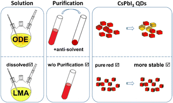 | ||
| Scheme 1 Schematic diagram of the conventional ODE strategy and the new LMA strategy for the fabrication process of the perovskite polymer composite films. | ||
Herein, we use lauryl methacrylate (LMA) instead of octadecene (ODE) as the reaction solvent to synthesize ultra-small CsPbI3 QDs with a diameter of only 4.2 nm through hot injection. LMA has been reported earlier as both a solvent and hydrophobic alkyl monomer for CsPbBr3 nanocrystal films.37 LMA enables perovskite polymer composite films to be formed without further purification and redispersion. In addition, the solubility of halide-rich precursors containing Mn is improved. The precipitation of PbI2 caused by higher feed ratios of Mn in the hot-injection reaction is solved as a result. By adjusting the amount of LMA, the emission peak of pristine CsPbI3 QD solution can be varied from 653 nm to 631 nm. α-CsPbI3 QDs are synthesized through adopting the feed ratio of Mn/Pb. The emission peaks of the corresponding QD films are adjusted in the bright red region of 638–627 nm. The bright red perovskite QD polymer composite films exhibit superior stability to conventional mixed halide perovskite nanocrystal polymer composite films. Under continuous intense irradiation, the mixed halide perovskite films undergo phase segregation and the PLQY decreases sharply within 3 hours. In contrast, the PLQY of the CsPbI3 QD polymer composite film still remains 73% after continuous irradiation for 24 hours. Thus, a down-conversion perovskite LED is fabricated using a green CsPbBr3 nanocrystal polymer composite film and a bright red CsPbI3 QD polymer composite film. Moreover, our modified method exhibits a scale-up possibility and reproducibility towards future display applications.
Results and discussion
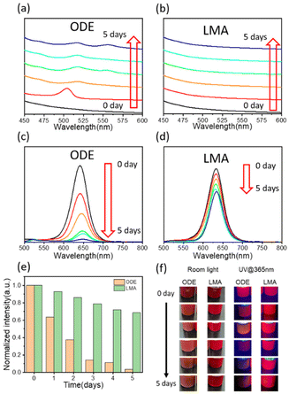
As for the cubic α-CsPbI3 phase, the Cs+ ions are not large enough to stabilize the cubic framework and a transition to the yellow non-emitting orthorhombic δ-CsPbI3 phase is seen below 315 °C.38 Mn2+ is used to enhance the formation energy and improve the stability of the CsPbX3 perovskite.32,39 However, higher feed ratios of Mn result in the precipitation of PbI2, which has been reported in a previous work.32 The comparison between CsPbI3 QD polymer composite films through ODE and LMA strategies are shown in Scheme 1. Compared to ODE, LMA exhibits better solubility for the precursor under the same experimental conditions (Fig. S1†). In the ODE process, the precursor cannot be completely dissolved, and the preparation of the perovskite composite film requires purification using anti-polar solvents to remove the ODE solution. Since the solubility of the precursor affects the halide-rich reaction conditions, Mn-doped CsPbI3 QDs can hardly reach bright red emission <640 nm through the direct hot-injection method.10,33 CsPbI3 perovskite QDs obtained using ODE exhibit an emission peak at 642 nm (Fig. S2a†). To separate QDs, perovskites need to be purified using methyl acetate. The removal of surface-bound ligands using polar anti-solvents results in the degradation of QDs.26–28 Without the protection of the surface ligands, small QDs are easily transferred to the non-emitting δ-CsPbI3. Furthermore, the CsPbI3 QDs are not yet stable in pristine ODE solution.As shown in Fig. 1a, the as-synthesized samples in pristine ODE solution exhibit no significant absorption peaks in the range from 450 nm to 600 nm. After 1 day, a peak around 504 nm appears, indicating that the ODE sample dissociates into monolayer nanocrystals.40 After 2 days, an absorption peak located at 517 nm is observed. This peak reflects the formation of monolayer nanoplates36 confirmed by the XRD patterns (Fig. S2b†). Aggregation, phase transition non-emitting phase and self-assembly to the monolayer41 nanosheets of the samples take place spontaneously after 2 days. The absorption peak at 555 nm appears after the storage of the samples for over 3 days. The peak is attributed to bi-layer nanocrystals.36,42 Compared to the ODE samples, the LMA samples exhibit superior stability (Fig. 1b). A monolayer peak appears after storage for over 6 days in the LMA solution (Fig. S3†).
The stability comparison between the samples in ODE and LMA can also be observed from the PL emission, as shown in Fig. 1c–e. It can be observed that after preservation for 5 days in the pristine solution, the PL intensity of the ODE samples decreases sharply to less than 5%, while the PL intensity of the LMA samples remain at approximately 68% with respect to the initial value. The PL emission peaks of the ODE solution shift from 640 nm to 648 nm after 4 days, while the emission peaks of the LMA samples exhibit nearly no shift until preservation in the solution for 7 days (Fig. S4†). The overall comparison of the optical properties between the two samples is shown directly in Fig. 1f. The degradation of CsPbI3 QDs is suppressed in LMA and the stability is improved as a result.
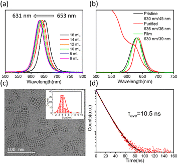
LMA provides a preferable environment for Mn-doped CsPbI3 QDs, which enabled us to conduct more studies on the synthesis of CsPbI3 QDs. As the high ligand concentration decreases the reactivity of the precursors and nucleus surfaces,43 we can adjust the amount of LMA to increase the concentration of the precursor, according to which the CsPbI3 QD solution with tunable emission is obtained. As shown in Fig. 2a, with the amount of LMA decreasing from 16 mL to 6 mL, the emission peaks of the QD solution shift from 653 nm to 631 nm. The PL and absorption spectra of CsPbI3 QDs synthesized using 16 mL of LMA exhibit a red shift compared with those synthesized using 8 mL of LMA after being diluted in toluene (Fig. S5†). As shown in Fig. 2b, the diluted pristine sample under the condition of 8 mL of LMA exhibits emission at 630 nm with a full width at half maximum (FWHM) of 45 nm. The corresponding QD film exhibits emission at 630 nm with a FWHM of 39 nm, which matches well with the Rec. 2020 standard. After being purified using methyl acetate for once, the PL emission peak shifts to 636 nm with a FWHM of 36 nm, and the absorption is around 620 nm. The CsPbI3 QDs exhibit a narrower FWHM compared to those in previous works11,44 in the bright red region. Purification using polar anti-solvents results in aggregation of small QDs, so a purification-free method for small QD films is also meaningful. The strong quantum confined effect results from the small particles with an average size of 4.2 nm, observed through transmission electron microscopy (TEM) images (Fig. 2c). Compared with the QDs synthesized using 8 mL of LMA, the CsPbI3 QDs obtained using 16 mL of LMA exhibit a larger mean size of 5.2 nm (Fig. S5†). There is no obvious difference in the Mn/Pb ratio between the QDs synthesized using 8 mL and 16 mL of LMA (Table S1 and Fig. S6†). Thus, the change of the PL peak position is attributed to the variation in QD size controlled through the concentration of precursors. The time-resolved PL (TRPL) decay spectrum is measured and fitted with bi-exponential decay functions as shown in Fig. 2d. The PL lifetimes (τavg) are listed in Table S2† (with the condition of Mn/Pb = 1.6).
Although doping of Mn2+ in CsPbBr3 and CsPbI3 cannot be detected through PL emission due to the mismatch between the 4T1 → 6A1 transition of Mn2+ and the band gap absorption of the perovskite,39,45 Mn2+ still has an impact on lead halide perovskites.
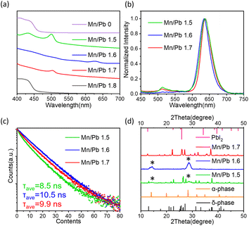
The stability of CsPbBr3 and CsPbI3 perovskites is influenced by the amount of Mn2+.32,39 Thus, the feed ratio of Mn/Pb has a crucial effect on the stability of small CsPbI3 QDs. The improved solubility of the precursor in LMA makes it possible to adjust the feed ratio of Mn/Pb for small QDs. As shown in Fig. 3a, the UV-vis absorption spectra indicate that CsPbI3 QDs with a feed ratio of Mn/Pb = 1.6 exhibit superior stability after being purified using methyl acetate twice, compared to the undoped CsPbI3 QDs and QDs with other feed ratios. The QDs with Mn/Pb = 1.6 exhibit an absorption peak at 625 nm. The red shift originates from the removal of surface ligands in the purification process using methyl acetate.25 In addition, QDs with the conditions of Mn/Pb = 1.5 and Mn/Pb = 1.7 exhibit an exciton absorption peak at around 500 nm, which comes from the formation of single layer nanocrystals36,46 dissociated from the QDs. QDs with the conditions of Mn/Pb = 0 and Mn/Pb = 1.8 turn into yellow precipitates after the same purification process and lose their luminescence. The PL peaks of the diluted pristine colloidal QD solution with the conditions of Mn/Pb = 1.5, 1.6 and 1.7 all centered at 630 nm (Fig. S7†). After being purified using methyl acetate once, the PL spectra of the QDs with the conditions of Mn/Pb = 1.5 and Mn/Pb = 1.7 show a small peak at 513 nm (Fig. 3b), which originates from the single layer nanocrystals,36,46 corresponding to the absorption spectra. The CsPbI3 QDs with a feed ratio of Mn/Pb = 1.6 exhibit a single emission peak. The PL decay curves and PL decay parameters of QDs with different feed ratios are shown in Fig. 3c and Table S2.† QDs with the conditions of Mn/Pb = 1.5 and Mn/Pb = 1.7 exhibit a triexponential decay. The τ1, τ2, and τ3 lifetime components belong to the band-edge recombination, shallow trap-mediated recombination and trap state, respectively.47 When Mn/Pb = 1.6, the triexponential decay curve of the QDs changes to a biexponential decay, and the lifetime component τ3 corresponding to the trap state disappears. In addition, the phase stability of the QDs is also related to the feed ratio. The samples purified using a large amount of methyl acetate are characterized by XRD, as shown in Fig. 3d. The XRD patterns indicate that CsPbI3 QDs with Mn/Pb = 1.6 adopt the α-phase perovskite structure.48 The samples with a lower feed ratio of Mn/Pb = 1.5 degrade to non-emitting δ-CsPbI3 and the samples with a higher feed ratio of Mn/Pb = 1.7 degrade to δ-CsPbI3 and PbI2, as can be seen in Fig. S8.† With increasing amount of Mn, the stability of CsPbI3 QDs improves first and then decreases. This phenomenon owes to the change of the formation energy caused by the different amounts of Mn.39 The formation energy will reach the maximum for perovskite after reaching a certain amount of Mn2+ content and then decrease rapidly with further increasing content of Mn2+. The enhanced formation energy improves the thermal stability and optical performance of the perovskite QDs. As for small CsPbI3 QDs, the amount of Mn is more critical. As shown in Fig. S9,† QDs with a feed ratio of Mn/Pb > 1.6 are less stable. After being purified using methyl acetate and dried on the Si substrate, the PL emission of QDs with Mn/Pb = 1.7 disappeared and Mn dissociated, while the QDs with Mn/Pb = 1.6 still remained stable. Notably, CsPbI3 QDs with an appropriate amount of Mn2+ exhibit superior stability.
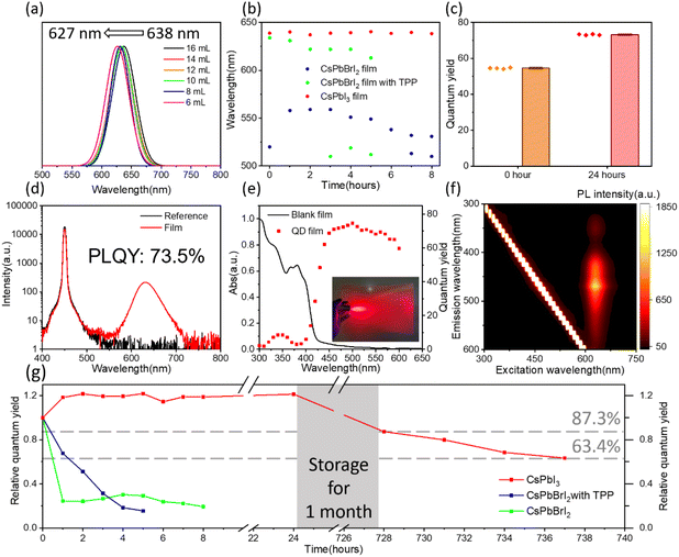
By adjusting the amount of LMA, the emission peaks of the QD solution are tunable, and the emission peaks of the corresponding QD films can be adjusted from 638 nm to 627 nm (Fig. 4a) in the bright red region. The CIE chromaticity coordinates of the red QD films from different amounts of LMA vary continuously from (0.69, 0.31) to (0.67, 0.33), as shown in Fig. S10.† A film with a PL emission peak at 630 nm is achieved under the condition of 8 mL of LMA with a FWHM of 39 nm. As for mixed halide perovskites, phase segregation can be aggravated under photo-illumination.49 Phase segregation results in color inhomogeneity and deviation, which limits the reliability of backlight applications.29 Thus, we used CsPbI3 QD films with bright red emission for backlight applications. CsPbI3 QD polymer composite films based on LMA are fabricated by photo-polymerization. We compared the optical properties of the bright red emissive films of mixed halide CsPbBrI2 nanocrystals and CsPbI3 QDs, as shown in Fig. 4. Triphenylphosphine (TPP)50 is used as a stabilizing agent for CsPbBrI2 films. Fig. S11† shows the cross-sectional images of the CsPbI3 QD composite film. The thickness of the samples within the two PET substrates is estimated to be ∼90 μm using scanning electron microscopy (SEM) images. The photostability test is executed using a home-made 450 nm LED lamp with irradiance of 1750 mW cm−2 in a dark room with a distance of 2.5 cm under a relative humidity (RH) of around 70% (Fig. S11d†). As shown in Fig. 4b, the CsPbBrI2 nanocrystals are unstable in the UV adhesive, leading to a peak blue-shift to 520 nm for the film without TPP. With the protection of TPP, the main peak of the CsPbBrI2 film shifts from 634 nm to 622 nm, and a second emission peak is detected at 510 nm after 3 h. For the mixed halide perovskites, phase segregation can be aggravated under illumination. The emission peaks of the CsPbI3 QD films exhibit merely no shift owing to their pure iodide composition.
The time-dependent PLQY characterization of perovskite films is performed as shown in Fig. 4g and Fig. S12.† The main initial emission peak of the CsPbBrI2 films without TPP was seen to be shifted to 520 nm already, meaning that phase segregation has occurred during the adhesive mixing process. The PLQY of the CsPbBrI2 films with TPP is 10.3% at the beginning and decreases rapidly under continuous irradiation, reflecting the instability of the mixed halide CsPbBrI2 perovskite. As for the CsPbI3 QD films, the PLQY has been improved from 61% to 71% and remain at 73.5% after 24 h. The increase in the PLQY after 1 h owes to the enhanced binding of the carboxylic acid from the ligand in the pristine QD solution.37,51 After continuous irradiation, the PLQY and emission peak position of the CsPbI3 QD films remain stable (Fig. 4b, g and Fig. S11c†). The morphology of the QD films exhibits no obvious change, as shown in Fig. S11b.† When the excitation wavelength varied from 440 nm to 600 nm, the PLQY of the CsPbI3 films did not decrease significantly (Fig. 4e) and the peak did not shift (Fig. 4f). As shown in Fig. 4e, the low PLQY with an excitation wavelength <440 nm is generated from the blank film. The change of the PLQY matches well with the absorption spectrum of the blank film. The PLQY of the CsPbI3 films fabricated using the other UV adhesive did not decrease significantly and the peak did not shift with the variation of the excitation wavelength from 420 nm to 600 nm (Fig. S13†). After 1 month of preservation at room temperature under an average RH over 60%, the PLQY of the CsPbI3 films decreased to 53% (Fig. S12†), remaining at 87.3% with respect to the initial ratio (Fig. 4g). After continuous intense irradiation for another 9 h, the PLQY decreased to 38%, remaining at 63.4% compared to the initial PLQY. It can be seen that the CsPbI3 films exhibit superior photostability compared to the mixed halide perovskite film. Therefore, by applying the CsPbI3 films, the deficiencies that limit the use of lead halide perovskites in LED backlights due to poor structural stability and phase segregation are alleviated in the bright red region.
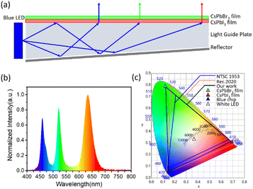
The stable CsPbI3 QD film exhibits emission at 630 nm with a narrow FWHM of 39 nm, which is suitable for display. Thus, a perovskite white LED is fabricated using a CsPbBr3 nanocrystal polymer composite film and a CsPbI3 QD polymer composite film. The emission spectra of the blue chip, CsPbBr3 film and CsPbI3 film are shown in Fig. S14.† As shown in Fig. 5a, a wide color gamut backlight is fabricated by successively superimposing a CsPbI3 QD composite film and a CsPbBr3 composite film on a blue source. The CIE chromaticity coordinates of the blue-chip, green-emissive CsPbBr3 film and bright red-emissive CsPbI3 film are (0.15, 0.05), (0.12, 0.79) and (0.69, 0.31), respectively. The CIE chromaticity coordinate of the white point is (0.36, 0.33), with a correlated color temperature (CCT) of 4000 K. The color gamut exceeds 128% of the NTSC1953 standard and 96% of the Rec. 2020 standard in the CIE 1931 color space. Moreover, the synthesis method can be scaled up. As shown in Fig. S15,† the precursor is completely dissolved, and around 250 mL of the colloidal QD solution is collected. The pristine solution exhibits PL emission centred at 630 nm with a FWHM of 44 nm, which is similar to the results shown in Fig. 2b. Thus, our modified method exhibits scale-up possibility and reproducibility towards future display applications.
Conclusions
In summary, we achieved α-CsPbI3 QD polymer composite films with superior stability in the bright red emission region through a precipitate-free method. By replacing ODE with LMA, the solubility of the precursor has been improved, and thus, a higher feed ratio of Mn for the smallest CsPbI3 QDs with a diameter of 4.2 nm is achieved so far. The emission peaks of CsPbI3 colloidal solution change from 653 nm to 631 nm by changing the amount of LMA. The emission peaks of QD films are tunable from 638 nm to 627 nm, with the corresponding CIE chromaticity coordinates varying from (0.69, 0.31) to (0.67, 0.33). Stable α-CsPbI3 QDs are obtained through an optimized feed ratio of Mn/Pb. Compared with CsPbBrI2 composite films, CsPbI3 QD composite films with emission at 630 nm (FWHM = 39 nm) exhibit superior stability and the peak shift caused by phase segregation is avoided. A white perovskite LED is fabricated using a CsPbBr3 nanocrystal polymer composite film and a CsPbI3 QD polymer composite film on a blue light source. An exceedingly wide color gamut of 96% has been achieved through our work relative to the Rec. 2020 standard in the CIE 1931 color space. Our modified method exhibits scale-up possibility and reproducibility towards future display applications. The proposed strategy using LMA paves a new way for effective doping of perovskites and has potential application in high-performance perovskite nanocrystals.Author contributions
The manuscript was written through contributions of all authors. All authors have given approval to the final version of the manuscript.Conflicts of interest
There are no conflicts to declare.Acknowledgements
This work was supported by the National Natural Science Foundation of China (22075129).References
- Z.-K. Tan, R. S. Moghaddam, M. L. Lai, P. Docampo, R. Higler, F. Deschler, M. Price, A. Sadhanala, L. M. Pazos, D. Credgington, F. Hanusch, T. Bein, H. J. Snaith and R. H. Friend, Nat. Nanotechnol., 2014, 9, 687–692 CrossRef CAS PubMed.
- Q. A. Akkerman, G. Rainò, M. V. Kovalenko and L. Manna, Nat. Mater., 2018, 17, 394–405 CrossRef CAS PubMed.
- X. Shen, Y. Zhang, S. V. Kershaw, T. Li, C. Wang, X. Zhang, W. Wang, D. Li, Y. Wang, M. Lu, L. Zhang, C. Sun, D. Zhao, G. Qin, X. Bai, W. W. Yu and A. L. Rogach, Nano Lett., 2019, 19, 1552–1559 CrossRef CAS PubMed.
- M. V. Kovalenko, L. Protesescu and M. I. Bodnarchuk, Science, 2017, 358, 745–750 CrossRef CAS PubMed.
- K. Lin, J. Xing, L. N. Quan, F. P. G. de Arquer, X. Gong, J. Lu, L. Xie, W. Zhao, D. Zhang, C. Yan, W. Li, X. Liu, Y. Lu, J. Kirman, E. H. Sargent, Q. Xiong and Z. Wei, Nature, 2018, 562, 245–248 CrossRef CAS PubMed.
- T. Chiba, Y. Hayashi, H. Ebe, K. Hoshi, J. Sato, S. Sato, Y.-J. Pu, S. Ohisa and J. Kido, Nat. Photonics, 2018, 12, 681–687 CrossRef CAS.
- Y. Cao, N. Wang, H. Tian, J. Guo, Y. Wei, H. Chen, Y. Miao, W. Zou, K. Pan, Y. He, H. Cao, Y. Ke, M. Xu, Y. Wang, M. Yang, K. Du, Z. Fu, D. Kong, D. Dai, Y. Jin, G. Li, H. Li, Q. Peng, J. Wang and W. Huang, Nature, 2018, 562, 249–253 CrossRef CAS PubMed.
- C. Bi, J. Hu, Z. Yao, Y. Lu, D. Binks, M. Sui and J. Tian, Adv. Funct. Mater., 2020, 30, 2005990 CrossRef CAS.
- P. Vashishtha and J. E. Halpert, Chem. Mater., 2017, 29, 5965–5973 CrossRef CAS.
- Y.-K. Wang, F. Yuan, Y. Dong, J.-Y. Li, A. Johnston, B. Chen, M. I. Saidaminov, C. Zhou, X. Zheng, Y. Hou, K. Bertens, H. Ebe, D. Ma, Z. Deng, S. Yuan, R. Chen, L. K. Sagar, J. Liu, J. Fan, P. Li, X. Li, Y. Gao, M.-K. Fung, Z.-H. Lu, O. M. Bakr, L.-S. Liao and E. H. Sargent, Angew. Chem., Int. Ed., 2021, 60, 16164–16170 CrossRef CAS PubMed.
- Y. F. Lan, J. S. Yao, J. N. Yang, Y. H. Song, X. C. Ru, Q. Zhang, L. Z. Feng, T. Chen, K. H. Song and H. B. Yao, Nano Lett., 2021, 21, 8756–8763 CrossRef CAS PubMed.
- A. Dutta, S. K. Dutta, S. Das Adhikari and N. Pradhan, ACS Energy Lett., 2018, 3, 329–334 CrossRef CAS.
- G. Almeida, L. Goldoni, Q. Akkerman, Z. Dang, A. H. Khan, S. Marras, I. Moreels and L. Manna, ACS Nano, 2018, 12, 1704–1711 CrossRef CAS PubMed.
- Y. Dong, T. Qiao, D. Kim, D. Parobek, D. Rossi and D. H. Son, Nano Lett., 2018, 18, 3716–3722 CrossRef CAS PubMed.
- Q. A. Akkerman, T. P. T. Nguyen, S. C. Boehme, F. Montanarella, D. N. Dirin, P. Wechsler, F. Beiglböck, G. Rainò, R. Erni, C. Katan, J. Even and M. V. Kovalenko, Science, 2022, 377, 1406–1412 CrossRef CAS PubMed.
- N. Pradhan, ACS Phys. Chem. Au, 2022, 2, 268–276 CrossRef CAS.
- L. Protesescu, S. Yakunin, M. I. Bodnarchuk, F. Krieg, R. Caputo, C. H. Hendon, R. X. Yang, A. Walsh and M. V. Kovalenko, Nano Lett., 2015, 15, 3692–3696 CrossRef CAS PubMed.
- Q. Wang, Z. Jin, D. Chen, D. Bai, H. Bian, J. Sun, G. Zhu, G. Wang and S. Liu, Adv. Energy Mater., 2018, 8, 1800007 CrossRef.
- J. Kim, B. Koo, W. H. Kim, J. Choi, C. Choi, S. J. Lim, J.-S. Lee, D.-H. Kim, M. J. Ko and Y. Kim, Nano Energy, 2019, 66, 104130 CrossRef CAS.
- J. Kim, S. Cho, F. Dinic, J. Choi, C. Choi, S. M. Jeong, J.-S. Lee, O. Voznyy, M. J. Ko and Y. Kim, Nano Energy, 2020, 75, 104985 CrossRef CAS.
- J. Khan, X. Zhang, J. Yuan, Y. Wang, G. Shi, R. Patterson, J. Shi, X. Ling, L. Hu, T. Wu, S. Dai and W. Ma, ACS Energy Lett., 2020, 5, 3322–3329 CrossRef CAS.
- J. Xue, R. Wang, L. Chen, S. Nuryyeva, T.-H. Han, T. Huang, S. Tan, J. Zhu, M. Wang, Z.-K. Wang, C. Zhang, J.-W. Lee and Y. Yang, Adv. Mater., 2019, 31, 1900111 CrossRef PubMed.
- A. Chakrabarty, S. Satija, U. Gangwar and S. Sapra, Chem. Mater., 2020, 32, 721–733 CrossRef CAS.
- S. Cho, J. Kim, S. M. Jeong, M. J. Ko, J.-S. Lee and Y. Kim, Chem. Mater., 2020, 32, 8808–8818 CrossRef CAS.
- S. Lim, G. Lee, S. Han, J. Kim, S. Yun, J. Lim, Y.-J. Pu, M. J. Ko, T. Park, J. Choi and Y. Kim, ACS Energy Lett., 2021, 6, 2229–2237 CrossRef CAS.
- Y. Wang, J. Yuan, X. Zhang, X. Ling, B. W. Larson, Q. Zhao, Y. Yang, Y. Shi, J. M. Luther and W. Ma, Adv. Mater., 2020, 32, 2000449 CrossRef CAS PubMed.
- E. Yassitepe, Z. Yang, O. Voznyy, Y. Kim, G. Walters, J. A. Castañeda, P. Kanjanaboos, M. Yuan, X. Gong, F. Fan, J. Pan, S. Hoogland, R. Comin, O. M. Bakr, L. A. Padilha, A. F. Nogueira and E. H. Sargent, Adv. Funct. Mater., 2016, 26, 8757–8763 CrossRef CAS.
- Y. Kim, E. Yassitepe, O. Voznyy, R. Comin, G. Walters, X. Gong, P. Kanjanaboos, A. F. Nogueira and E. H. Sargent, ACS Appl. Mater. Interfaces, 2015, 7, 25007–25013 CrossRef CAS PubMed.
- X. Wang, Z. Bao, Y.-C. Chang and R.-S. Liu, ACS Energy Lett., 2020, 5, 3374–3396 CrossRef CAS.
- M. Liu, L. Ma, K. Xie, P. Zeng, S. Wei, F. Zhang, C. Li and F. Wang, J. Phys. Chem. Lett., 2022, 1519–1525 CrossRef PubMed.
- Z. Dai, J. Chen and B. Yang, J. Phys. Chem. Lett., 2021, 10093–10098 CrossRef CAS PubMed.
- Q. A. Akkerman, D. Meggiolaro, Z. Dang, F. De Angelis and L. Manna, ACS Energy Lett., 2017, 2, 2183–2186 CrossRef CAS PubMed.
- H. Ebe, Y.-K. Wang, N. Shinotsuka, Y.-H. Cheng, M. Uwano, R. Suzuki, Y. Dong, D. Ma, S. Lee, T. Chiba, E. H. Sargent and J. Kido, ACS Appl. Mater. Interfaces, 2022, 14, 17691–17697 CrossRef CAS PubMed.
- W. J. Mir, A. Alamoudi, J. Yin, K. E. Yorov, P. Maity, R. Naphade, B. Shao, J. Wang, M. N. Lintangpradipto, S. Nematulloev, A.-H. Emwas, A. Genovese, O. F. Mohammed and O. M. Bakr, J. Am. Chem. Soc., 2022, 144, 13302–13310 CrossRef CAS PubMed.
- M. Xie, J. Guo, X. Zhang, C. Bi, L. Zhang, Z. Chu, W. Zheng, J. You and J. Tian, Nano Lett., 2022, 22, 8266–8273 CrossRef CAS PubMed.
- C. Otero-Martínez, J. Ye, J. Sung, I. Pastoriza-Santos, J. Pérez-Juste, Z. Xia, A. Rao, R. L. Z. Hoye and L. Polavarapu, Adv. Mater., 2022, 34, 2107105 CrossRef PubMed.
- J. Tong, J. Wu, W. Shen, Y. Zhang, Y. Liu, T. Zhang, S. Nie and Z. Deng, ACS Appl. Mater. Interfaces, 2019, 11, 9317–9325 CrossRef CAS PubMed.
- W. Ahmad, J. Khan, G. Niu and J. Tang, Sol. RRL, 2017, 1, 1700048 CrossRef.
- S. Zou, Y. Liu, J. Li, C. Liu, R. Feng, F. Jiang, Y. Li, J. Song, H. Zeng, M. Hong and X. Chen, J. Am. Chem. Soc., 2017, 139, 11443–11450 CrossRef CAS PubMed.
- Y. Hassan, Y. Song, R. D. Pensack, A. I. Abdelrahman, Y. Kobayashi, M. A. Winnik and G. D. Scholes, Adv. Mater., 2016, 28, 566–573 CrossRef CAS PubMed.
- B. P. Kore and J. M. Gardner, Mater. Adv., 2020, 1, 2395–2400 RSC.
- M. C. Weidman, M. Seitz, S. D. Stranks and W. A. Tisdale, ACS Nano, 2016, 10, 7830–7839 CrossRef CAS PubMed.
- J. C. Sadighian and C. Y. Wong, J. Phys. Chem. C, 2021, 125, 20772–20782 CrossRef CAS.
- L. Yang, Y. Zhang, J. Ma, P. Chen, Y. Yu and M. Shao, ACS Energy Lett., 2021, 6, 2386–2394 CrossRef CAS.
- W. Liu, Q. Lin, H. Li, K. Wu, I. Robel, J. M. Pietryga and V. I. Klimov, J. Am. Chem. Soc., 2016, 138, 14954–14961 CrossRef CAS PubMed.
- C. Wang, Y.-K. Wang, Z. Li, J. Luo, R. Sabatini, T. Zhang, E. H. Sargent and Z. Deng, Adv. Opt. Mater., 2022, 10, 2200217 CrossRef CAS.
- V. G. V. Dutt, S. Akhil, R. Singh, M. Palabathuni and N. Mishra, J. Phys. Chem. C, 2022, 126, 9502–9508 CrossRef CAS.
- A. Marronnier, G. Roma, S. Boyer-Richard, L. Pedesseau, J.-M. Jancu, Y. Bonnassieux, C. Katan, C. C. Stoumpos, M. G. Kanatzidis and J. Even, ACS Nano, 2018, 12, 3477–3486 CrossRef CAS PubMed.
- E. T. Hoke, D. J. Slotcavage, E. R. Dohner, A. R. Bowring, H. I. Karunadasa and M. D. McGehee, Chem. Sci., 2015, 6, 613–617 RSC.
- J. Wu, J. Tong, Y. Gao, A. Wang, T. Zhang, H. Tan, S. Nie and Z. Deng, Angew. Chem., Int. Ed., 2020, 59, 7738–7742 CrossRef CAS PubMed.
- J. De Roo, M. Ibáñez, P. Geiregat, G. Nedelcu, W. Walravens, J. Maes, J. C. Martins, I. Van Driessche, M. V. Kovalenko and Z. Hens, ACS Nano, 2016, 10, 2071–2081 CrossRef CAS PubMed.
Footnote |
| † Electronic supplementary information (ESI) available. See DOI: https://doi.org/10.1039/d2nr05456f |
| This journal is © The Royal Society of Chemistry 2023 |

