Highly active conversion of CO2 to CO on AuCuB materials†
Yuting
Liu‡
a,
Yuan
Fang‡
 ab,
Qinghong
Yuan
 *b,
Jiaxing
Lu
 ac and
Huan
Wang
 *ac
*ac
aShanghai Key Laboratory of Green Chemistry and Chemical Process, School of Chemistry and Molecular Engineering, East China Normal University, 3663 North Zhongshan Rd., Shanghai 200062, China. E-mail: hwang@chem.ecnu.edu.cn
bState Key Laboratory of Precision Spectroscopy, School of Physics and Electronic Science, East China Normal University, 500 Dongchuan Road, Shanghai 200241, China. E-mail: qhyuan@phy.ecnu.edu.cn
cInstitute of Eco-Chongming, 20 Cuiniao Road, Chenjia Town, Chongming District, Shanghai 202162, China
First published on 26th January 2023
Abstract
The electrochemical CO2 reduction reaction is an attractive solution for converting CO2 into reusable chemicals. However, the low activity of the catalysts restricts its widespread application for conversion. This study uses a simple one-pot method to prepare B-doped AuCu alloy (AuCuB) materials. AuCuB-400 demonstrated a superior faradaic efficiency (FE) for CO [99% at −1.16 V vs. the reversible hydrogen electrode (RHE)], whereas the FECO of AuCu was much lower (42%). Operando electrochemical Raman spectroscopy and density functional theory (DFT) calculations revealed that incorporating B could tune the electronic structure of AuCu to promote the adsorption of CO intermediates, thus facilitating the conversion of CO2 to CO. These findings will provide a good approach for designing highly active alloy catalysts for converting CO2 to CO.
Increasing CO2 emissions have resulted in various issues, such as global warming and rising sea levels.1 Various approaches have been proposed to capture and utilize CO2 to mitigate these serious issues.2,3 One of the most promising approaches is the electrochemical CO2 reduction reaction (CO2RR), which represents a straightforward and environment-friendly strategy to transform CO2 into valuable products (CO, HCOOH, C2H4, etc.).4–6 However, some intrinsic challenges dramatically hinder the development of this method, such as poor selectivity, low partial current density, and low faradaic efficiency (FE).7 Numerous efforts have been devoted to this field to solve these problems, including designing electrocatalysts and optimizing electrolytes, electrolyzers, and ion exchange membranes.8–12
Exploring efficient and robust electrocatalysts are an important part of CO2RR,13 because they can reduce the energy barrier of the reaction and improve the selectivity of specific products. Although some non-metal materials exhibit superior FECO,14–16 metal catalysts have better conductivity and higher current density than non-metal catalysts. Among various metal catalysts, Au is a well-known electrocatalyst for CO2RR to form CO. However, its high cost limits its commercial development and application.17,18 Therefore, Au-transition bimetallic materials have been reported to reduce the cost while improving the catalytic efficiency.19 For example, the maximum FECO of the ordered Au–Cu catalyst synthesized by the Yang group is 80%, which is significantly greater than those of pure Au-catalysts reported previously.20 Additionally, the performance of the catalysts can be further improved by the incorporation of non-metallic atoms, such as nitrogen,21 boron (B),22–28 and sulfur.29 This is because of the adjustment of valence electrons or structure of the catalyst. B is quite favored among these non-metallic atoms because of its high electronegativity, which helps with electron transfer to alter the energetics of the reaction intermediates by shifting the d-band center or electrostatic interactions and promotes electrocatalytic performance.27,30–32 Catalysts doped with B, such as B-doped Ag nanosponges,33 B–Pd interstitial nanocrystals,34 and PdRuBP nanospine assemblies,35 have been widely used in electrochemistry, exhibiting excellent catalytic activity. The study of B-doped Pd catalysts revealed higher formate production over a wide potential range compared to undoped Pd. The result can be attributed to the downshift of the d band center of surface Pd atoms due to the charge transfer between B and Pd after doping B.36 Han et al. revealed that under the impact of charge transfer between Cu and B, a B-doped oxide-derived-Cu catalyst exhibited higher FEC2 products (C2H4, C2H6 and C2H5OH, 48.2%) than a B-free oxide-derived-Cu catalyst (30.5%).37 Although B-modified metallic materials have been studied in several literature reports, achieving a higher FE toward a specific product remains a significant challenge in CO2RR.
Herein, this study presents a B-doped AuCu alloy (AuCuB) for efficient CO2RR. Operando electrochemical Raman spectroscopy and density functional theory (DFT) calculations were combined to obtain convincing evidence that AuCuB shows significant activity in converting CO2 to CO, owing to improved *COOH adsorption.
The AuCuB-400 material was synthesized by reducing HAuCl4·H2O and CuCl2·2H2O in an N,N-dimethylformamide (DMF) solution using NaBH4 as a boron source and reducing agent. For comparison, the same procedure was used to synthesize the AuCu-400 material; however, DMF was replaced by H2O (refer to the ESI† for details). The results of inductively coupled plasma-atomic emission spectrometry (ICP-AES) indicated that ca. 3.93 at% of B was doped in AuCuB-400 catalysts, but no B was detected in AuCu-400. X-ray diffraction (XRD) was conducted to confirm the crystal structure of AuCu-400 and AuCuB-400. As shown in Fig. 1A, the five diffraction peaks at 2-theta values of 38.1°, 44.3°, 64.5°, 77.6°, and 81.7° corresponded to the crystal planes of (111), (200), (220), (311), and (222) for the AuCu-400 material, respectively. The diffraction peaks of the AuCuB-400 material shifted to higher angles. For both AuCuB-400 and AuCu-400, the absence of distinct Cu diffraction peaks and the similar molar ratio of Cu and Au (1![[thin space (1/6-em)]](https://www.rsc.org/images/entities/char_2009.gif) :
:![[thin space (1/6-em)]](https://www.rsc.org/images/entities/char_2009.gif) 2.8, by ICP-AES) indicate that Cu and Au exist in the form of an alloy. Notably, when compared with AuCu-400, the main shift in the diffraction peak of AuCuB-400 implies that B doping caused the lattice expansion, which is consistent with the previously reported literature.36
2.8, by ICP-AES) indicate that Cu and Au exist in the form of an alloy. Notably, when compared with AuCu-400, the main shift in the diffraction peak of AuCuB-400 implies that B doping caused the lattice expansion, which is consistent with the previously reported literature.36
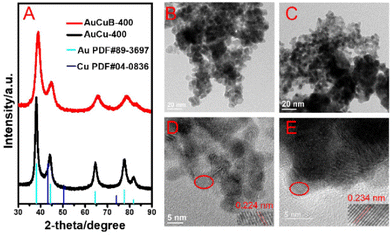 | ||
| Fig. 1 X-ray diffraction (A) of AuCu-400 (black line) and AuCuB-400 (red line). TEM images (B and C) and the corresponding HRTEM images (D and E) of AuCuB-400 (B and E) and AuCu-400 (C and D). | ||
Transmission electron microscopy (TEM) images (Fig. 1B and C) showed that the as-synthesized AuCu-400 and AuCuB-400 were mainly composed of nanoparticles. The corresponding particle size distribution histograms of AuCu-400 and AuCuB-400 were comparable (5.5–6 and 4.5–5.5 nm, Fig. S1†). The lattice fringes with d-spacings of 0.224 and 0.234 nm corresponded to the (111) planes of AuCu-400 and AuCuB-400 (Fig. 1D and E), respectively, which were analyzed by high-resolution transmission electron microscopy (HRTEM). Compared with AuCu-400, the interplanar spacing of AuCuB-400 was enlarged due to the effective B-doping. Combining the results of XRD, HRTEM and ICP-AES, it can be observed that B was successfully incorporated into the crystal lattice of AuCu-400.
To understand the preparation process, some controlled experiments have been carried out (Table S1†). Interestingly, no B was detected in Au(B) when CuCl2·2H2O was not added to the reaction solution (entry 2), whereas no solid material was obtained in the absence of HAuCl4·H2O (entry 3), indicating that Cu was not reduced in this case. These suggest that the coexistence of three substances in DMF (entry 1) is key to the synthesis of AuCuB. The possible reactions of NaBH4 are shown in Fig. S2.† The decomposition of BH4− in DMF may occur on the surface of AuCu (or Cu) (entries 1, 4 and 6), which contributes to the doping of B.
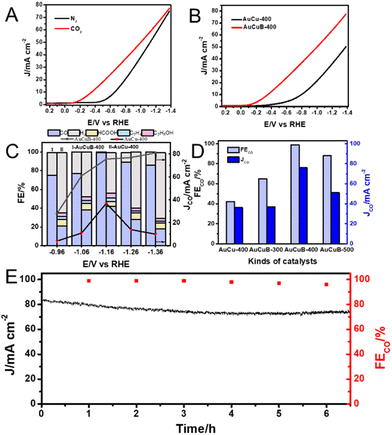
To investigate the electrocatalytic performance of the two materials for CO2RR, linear sweep voltammetry (LSV) measurements were conducted. As shown in Fig. 2A, the hydrogen evolution reaction occurred inevitably under an N2 atmosphere (black curve). Under CO2-saturated conditions, an obvious increase in the current density of AuCuB-400 was detected, which can be attributed to the electroreduction of CO2 (red curve). Additionally, a positive shift in the onset potential occurred from the initial −0.40 to −0.10 V. Similar behaviors were observed for AuCu-400 (Fig. S3†). A controlled experiment was conducted between AuCuB-400 and AuCu-400 to examine the effect of B incorporation in CO2RR. As shown in Fig. 2B, the onset potential of AuCuB-400 (−0.10 V vs. RHE) was more positive than that of AuCu-400 (−0.25 V vs. RHE), indicating the excellent CO2RR performance of AuCuB-400 as the catalyst.
To further investigate the catalytic activity and selectivity of the AuCu-400 and AuCuB-400 materials in CO2RR, potentiostatic electrolysis was conducted in CO2-saturated 1 M KOH solution with a gas diffusion electrode. As shown in Fig. 2C, in the case of the AuCuB-400 material, the major products were CO and H2, while the constituents of products using AuCu-400 were significantly complex (CO, HCOOH, H2, C2H4, and C2H5OH), revealing the high selectivity of AuCuB-400 in CO2RR for CO. Additionally, from −0.96 to −1.36 V vs. RHE, the AuCuB-400 catalyst displayed much higher FECO and JCO values than AuCu-400, indicating the advantage of AuCuB-400 in CO2RR to form CO, which can be distinctly attributed to the incorporation of B. The application of AuCuB-400 even achieved a remarkable FECO of 99% when the testing potential was −1.16 V vs. RHE, indicating the high activity of AuCuB-400 in CO2RR to form CO. These values are higher than those of most of the existing high performance materials for converting CO2 to CO (Table S2†).
The effect of the B content on the catalyst activity was further investigated. In this case, AuCuB-300 and AuCuB-500 were synthesized by altering the amount of NaBH4 to 300 and 500 μmol (Table S3 and Fig. S4, S5†). Overall, AuCuB-400 outperformed the other AuCuB materials in terms of catalytic performance (Fig. S6†). When the potential was set at −1.16 V vs. RHE, the maximum FECO for AuCuB-300, AuCuB-400, and AuCuB-500 was 65%, 99%, and 88%, respectively (Fig. 2D), demonstrating a trend of decline after increasing with an increase in the B content. The partial current density for CO showed a similar trend with the increase in the B content (Fig. 2D).
The stability in catalytic activity is essential for electrocatalysts. Hence, the long-term electrolysis of AuCuB-400 was conducted using chronoamperometry (Fig. 2E). Negligible decay was observed in both current density and FECO during the continuous electrolysis (approximately 6.5 h). Moreover, no obvious morphological changes and B leaching (from 3.93 at% to 3.50 at%) of AuCuB-400 were observed after long-term electrolysis by TEM and ICP-AES (Fig. S7†), implying its high stability.
Electrochemical impedance spectroscopy was performed to further investigate the reaction kinetics of the AuCuB-400 and AuCu-400 materials. The plot of AuCuB-400 showed a smaller diameter than that of AuCu-400 (Fig. 3A), indicating a lower interfacial charge transfer resistance. This implies that AuCuB-400 is beneficial for accelerating the electron transfer between the catalyst and reactant. The electrochemical surface areas of the AuCuB-400 and AuCu-400 materials were also tested using double-layer capacitance. AuCuB-400 presented a larger double-layer capacitance (9.84 mF cm−2) than AuCu-400 (2.23 mF cm−2, Fig. 3B and Fig. S8†), implying a larger electrochemical active surface area which is beneficial for promoting CO2RR.
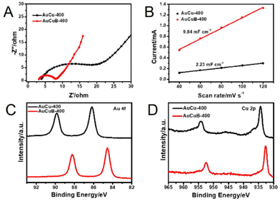 | ||
| Fig. 3 Nyquist plots (A), the linear relationship between the current and scan rate (B), high-resolution XPS spectra of Au 4f (C) and Cu 2p (D) of AuCu-400 (black line) and AuCuB-400 (red line). | ||
It is hypothesized that the high activity of the catalyst is caused by B doping, which can affect the local electronic structure.28 Hence, this study analyzed the local electronic structure of AuCuB using X-ray photoelectron spectroscopy (XPS). As shown in Fig. 3C, Au 4f in AuCuB-400 had two distinct characteristic peaks with binding energies of 84.54 and 88.22 eV for Au 4f7/2 and Au 4f5/2, respectively.38 The Cu 2p1/2 and Cu 2p3/2 peaks appeared at 932.72 and 952.52 eV for Cu 2p, corresponding to a valence of Cu(0) or Cu(I) (Fig. 3D).39 Au 4f and Cu 2p significantly shifted to a higher binding energy in AuCuB-400 compared with AuCu-400, implying that charge transfer occurred between B and AuCu.40,41 Fig. S9† shows the charge density difference of AuCuB with and without B doping, in which charge transfer from the metal to B is apparently shown. The charge transfer may affect the adsorption of intermediates and further influence the electrocatalytic performance.
To further explore the reaction process, operando Raman spectroscopy experiments were conducted from 0.15 to −0.45 V vs. RHE in CO2-saturated 1 M KOH solution. Herein, the reference potential was 0.15 V vs. RHE (CO2RR did not occur at this potential). As shown in Fig. 4, due to the adsorption of *CO on Cu and Cu–CO stretching, AuCu-400 exhibited the Raman peaks at 301 and 389 cm−1, while the corresponding Raman peaks of AuCuB-400 were at 272 and 354 cm−1. The charge transfer between the B atom and AuCu was mostly responsible for the blue shift after B doping.42,43 The absence of a *CO adsorption peak on Au was possibly caused by the rather weak binding strength of *CO and its fast desorption from Au surfaces, which correlated well with the previous study by Dunwell et al.44 Notably, Cu–CO and *CO on AuCuB-400 were detected at more positive potential (0.1 V vs. RHE) than those on AuCu-400 (−0.25 V vs. RHE), indicating that the activation of CO2 can be achieved at more positive potential and the superior activity of AuCuB converts CO2 into CO. The LSV curves perfectly represented the results.
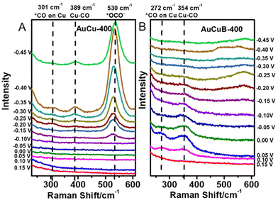 | ||
| Fig. 4 Potential-dependent operando Raman spectra recorded on AuCu-400 (A) and AuCuB-400 (B) in 1 M KOH. | ||
The *CO bridge and *CO stretching peaks appeared at 1860 and 2060 cm−1 (Fig. S10†) for AuCu-400, representing the key intermediate for C–C coupling.45–50 Nevertheless, neither of these *CO peaks was observed in the Raman spectra of AuCuB-400, indicating that incorporating B is not in favor of the formation of C2 intermediates, which coincides with the electrolysis result (Fig. 2C). As shown in Fig. 4A, the *OCO− intermediate at 530 cm−1 was detected for AuCu-400, which is the key intermediate for generating HCOOH.46 In contrast, no *OCO− peak was observed in the Raman spectra of AuCuB-400 (Fig. 4B), indicating that incorporating B inhibits the generation of HCOOH in CO2 electroreduction.
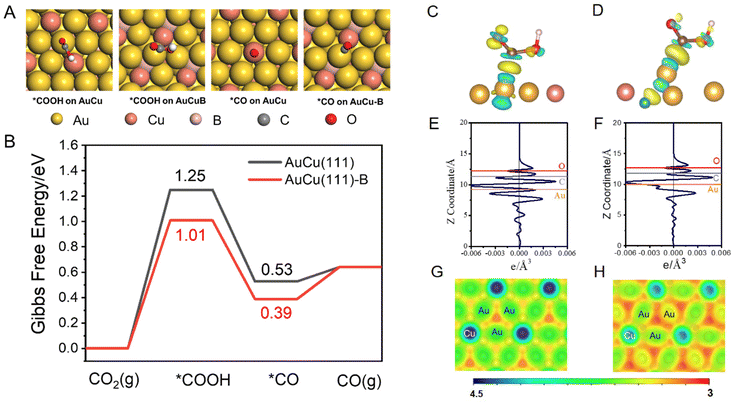
DFT calculations were performed to explore the role of the incorporated B in the AuCu intermetallic compound in the conversion of CO2 to CO [refer to the ESI for details, eqn (S6)–(S8)†].51 A AuCu(111) facet (Fig. S11A†) was used as the model surface because of its high thermodynamic stability. The doped B was introduced as an interstitial atom at the octahedral site between the topmost layer and sublayer of AuCu(111) (Fig. S11B†), denoted as AuCu(111)-B. Such a model has been proposed in previous experimental and theoretical studies.28,52 The CO2 reduction to CO proceeds through two proton-coupled electron transfer (PCET) steps and via the formation of *COOH, followed by a C–O bond break to yield CO.53 Adsorption configurations of *COOH and *CO on AuCu(111) and AuCu(111)-B are shown and compared in Fig. 5A. The free energy changes were obtained according to the computational hydrogen electrode model, proposed by Norskov.54,55Fig. 5B shows the Gibbs free energy profiles of CO2RR to form CO. The formation of *COOH requires a high energy gain, making it the dominant process in CO2RR to form CO and determining the limiting potential. The *COOH formation on AuCu(111)-B requires lower free energy gain (1.01 eV) than that on AuCu(111) (1.25 eV), demonstrating the easier formation of *COOH on the AuCu(111)-B surface. The solvation effect was also considered using the VASPSol code interfaced with VASP (Fig. S12†).56 The overall trend remains identical with the one having no solvation effect. The stronger *COOH binding on AuCu(111)-B can be also observed from the charge density difference (CDD) plots (Fig. 5C and D). The *COOH radical binds to surface Au via the C atom on both surfaces and the Au atom donates electrons to C and O atoms in the carbonyl group. For *COOH binding on the AuCu(111)-B surface, more electron transfer is observed from the planar-averaged CDD along the Z direction. As shown in Fig. 5E and F, compared with AuCu(111), more electron depletion around Au and more electron accumulation around C and O are exhibited for the AuCu(111)-B surface. Such a phenomenon can be understood from the surface electrostatic potential (Fig. 5G and H). The regions among surface Au (shown in red) have a more negative electrostatic potential on AuCu(111)-B than on AuCu(111), indicating the higher ability for the adsorption of electrophiles (*COOH in this case). To summarize, the doping of B into the AuCu(111) surface gives rise to the higher nucleophilicity of the Au surface and thus the stronger ability for *COOH adsorption. As a consequence, the free energy gain of CO2 that undergoes a PCET step to give *COOH is lowered on AuCu (111)-B than on AuCu(111) and the rate is accelerated by 4 orders of magnitude.
In summary, this study successfully prepared the AuCuB material using a simple one-pot method. The synthesized AuCuB-400 catalysts exhibited superior performance to the AuCu-400 alloy. The FECO of AuCuB-400 even reached 99% with a partial current density of 76 mA cm−2 at −1.16 V. Combining operando Raman spectroscopy with DFT calculations reveals that B doping is crucial in determining the high activity of the catalyst by tuning the electronic structures and thus the strong ability for *COOH adsorption on AuCuB. These findings will serve as a good strategy for the high performance of CO2 electroreduction to form CO.
Author contributions
H. W. and J. L. conceived the idea for the project. Y. L. performed the design of electrocatalytic experiments and the structural characterization. Y. L. and H. W. conducted the performance measurements and data analysis. Y. F. and Q. Y. performed the DFT calculations. Y. L. and Y. F. wrote the manuscript. H. W., J. L. and Q. Y. supervised the project. All authors discussed the results and commented on the manuscript at all stages.Conflicts of interest
The authors declare no conflicts of interest.Acknowledgements
This work was financially supported by the National Key R&D Program of China (2020YFA0710200), the National Natural Science Foundation of China (22072046 and 22173031) and the Research Funds of Happiness Flower ECNU (2020ST2203). The authors also thank Dr Qingsong Xue from East China Normal University for his constructive assistance with the gas chromatography measurement.References
- F. Orsini and P. Marrone, J. Cleaner Prod., 2019, 241, 118380 CrossRef.
- M. Aresta, A. Dibenedetto and A. Angelini, Chem. Rev., 2014, 114, 1709–1742 CrossRef CAS PubMed.
- S. Overa, T. G. Feric, A.-H. A. Park and F. Jiao, Joule, 2021, 5, 8–13 CrossRef.
- J. B. Greenblatt, D. J. Miller, J. W. Ager, F. A. Houle and I. D. Sharp, Joule, 2018, 2, 381–420 CrossRef CAS.
- D. G. Nocera, Acc. Chem. Res., 2017, 50, 616–619 CrossRef CAS PubMed.
- P. De Luma, C. Hahn, D. Higgins, S. A. Jaffer, T. F. Jaramillo and E. H. Sargent, Science, 2019, 364, eaav3506 CrossRef PubMed.
- J. Liang, D. Chen, X. Yao, K. Zhang, F. Qu, L. Qin, Y. Huang and J. Li, Small, 2020, 16, 1903398 CrossRef CAS PubMed.
- S. Overa, B. H. Ko, Y. Zhao and F. Jiao, Acc. Chem. Res., 2022, 55, 638–648 CrossRef CAS PubMed.
- Y. Cheng, P. Hou, X. Wang and P. Kang, Acc. Chem. Res., 2022, 55, 231–240 CrossRef CAS PubMed.
- I. Siewert, Acc. Chem. Res., 2022, 55, 473–483 CrossRef CAS PubMed.
- L. Li, X. Li, Y. Sun and Y. Xie, Chem. Soc. Rev., 2022, 51, 1234–1252 RSC.
- G. Wang, J. Chen, Y. Ding, P. Cai, L. Yi, Y. Li, C. Tu, Y. Hou, Z. Wen and L. Dai, Chem. Soc. Rev., 2021, 50, 4993–5061 RSC.
- K. P. Kuhl, E. R. Cave, D. N. Abram and T. F. Jaramillo, Energy Environ. Sci., 2012, 5, 7050–7059 RSC.
- X. Duan, J. Xu, Z. Wei, J. Ma, S. Guo, S. Wang, H. Liu and S. Dou, Adv. Mater., 2017, 29, 1701784 CrossRef PubMed.
- T. Asefa, Acc. Chem. Res., 2016, 49, 1873–1883 CrossRef CAS PubMed.
- M. Zhou, H.-L. Wang and S. Guo, Chem. Soc. Rev., 2016, 45, 1273–1307 RSC.
- H. Chen, Z. Li, Z. Zhang, K. Jie, J. Li, H. Li, S. Mao, D. Wang, X. Lu and J. Fu, Ind. Eng. Chem. Res., 2019, 58, 15425–15431 CrossRef CAS.
- Y. Han, Z. Wang, X. Han, W. Fang, Y. Zhou, K. Lei, B. You, H. S. Park and B. Y. Xia, ACS Sustainable Chem. Eng., 2021, 9, 2609–2615 CrossRef CAS.
- D. Siltamaki, S. Chen, F. Rahmati, J. Lipkowski and A-C. Chen, J. Electrochem., 2021, 27, 278–290 CAS.
- D. Kim, C. Xie, N. Becknell, Y. Yu, M. Karamad, K. Chan, E. J. Crumlin, J. K. Nørskov and P. Yang, J. Am. Chem. Soc., 2017, 139, 8329–8336 CrossRef CAS PubMed.
- Z.-Q. Liang, T.-T. Zhuang, A. Seifitokaldani, J. Li, C.-W. Huang, C.-S. Tan, Y. Li, P. De Luna, C. T. Dinh, Y. Hu, Q. Xiao, P.-L. Hsieh, Y. Wang, F. Li, R. Quintero-Bermudez, Y. Zhou, P. Chen, Y. Pang, S.-C. Lo, L.-J. Chen, H. Tan, Z. Xu, S. Zhao, D. Sinton and E. H. Sargent, Nat. Commun., 2018, 9, 3828 CrossRef PubMed.
- J. Xu and M. Saeys, J. Catal., 2006, 242, 217–226 CrossRef CAS.
- J. Xu and M. Saeys, J. Phys. Chem. C, 2009, 113, 4099–4106 CrossRef CAS.
- J. Xu, L. Chen, K. F. Tan, A. Borgna and M. Saeys, J. Catal., 2009, 261, 158–165 CrossRef CAS.
- K. F. Tan, J. Chang, A. Borgna and M. Saeys, J. Catal., 2011, 280, 50–59 CrossRef CAS.
- K. Jiang, K. Xu, S. Zou and W.-B. Cai, J. Am. Chem. Soc., 2014, 136, 4861–4864 CrossRef CAS PubMed.
- C. W. A. Chan, A. H. Mahadi, M. M.-J. Li, E. C. Corbos, C. Tang, G. Jones, W. C. H. Kuo, J. Cookson, C. M. Brown, P. T. Bishop and S. C. E. Tsang, Nat. Commun., 2014, 5, 5787 CrossRef CAS PubMed.
- Y. Zhou, F. Che, M. Liu, C. Zou, Z. Liang, P. De Luna, H. Yuan, J. Li, Z. Wang, H. Xie, H. Li, P. Chen, E. Bladt, R. Quintero-Bermudez, T.-K. Sham, S. Bals, J. Hofkens, D. Sinton, G. Chen and E. H. Sargent, Nat. Chem., 2018, 10, 974–980 CrossRef CAS PubMed.
- T.-T. Zhuang, Z.-Q. Liang, A. Seifitokaldani, Y. Li, P. De Luna, T. Burdyny, F. Che, F. Meng, Y. Min, R. Quintero-Bermudez, C. T. Dinh, Y. Pang, M. Zhong, B. Zhang, J. Li, P.-N. Chen, X.-L. Zheng, H. Liang, W.-N. Ge, B.-J. Ye, D. Sinton, S.-H. Yu and E. H. Sargent, Nat. Catal., 2018, 1, 421–428 CrossRef CAS.
- J.-Y. Wang, Y.-Y. Kang, H. Yang and W.-B. Cai, J. Phys. Chem. C, 2009, 113, 8366–8372 CrossRef CAS.
- Y. Okamoto, Y. Nitta, T. Imanaka and S. Teranishi, J. Chem. Soc., Faraday Trans., 1979, 75, 2027–2039 RSC.
- B. Hammer and J. K. Norskov, Nature, 1995, 376, 238–240 CrossRef CAS.
- Y. Li, H. Yu, Z. Wang, S. Liu, Y. Xu, X. Li, L. Wang and H. Wang, Chem. Commun., 2019, 55, 14745–14748 RSC.
- J. Li, J. Chen, Q. Wang, W.-B. Cai and S. Chen, Chem. Mater., 2017, 29, 10060–10067 CrossRef CAS.
- Y. Xu, S. Yu, T. Ren, C. Li, S. Yin, Z. Wang, X. Li, L. Wang and H. Wang, J. Mater. Chem. A, 2020, 8, 2424–2429 RSC.
- B. Jiang, X.-G. Zhang, K. Jiang, D.-Y. Wu and W.-B. Cai, J. Am. Chem. Soc., 2018, 140, 2880–2889 CrossRef CAS PubMed.
- C. Chen, X. Sun, L. Lu, D. Yang, J. Ma, Q. Zhu, Q. Qian and B. Han, Green Chem., 2018, 20, 4579–4583 RSC.
- Q. Liu, Q. Chen, T. Li, Q. Ren, S. Zhong, Y. Zhao and S. Bai, J. Mater. Chem. A, 2019, 7, 27007–27015 RSC.
- H. Li, T. Liu, P. Wei, L. Lin, D. Gao, G. Wang and X. Bao, Angew. Chem., Int. Ed., 2021, 60, 14329–14333 CrossRef CAS PubMed.
- Y. Mi, S. Shen, X. Peng, H. Bao, X. Liu and J. Luo, ChemElectroChem, 2019, 6, 2393–2397 CrossRef CAS.
- H. Li, T.-W. Jiang, X. Qin, J. Chen, X.-Y. Ma, K. Jiang, X.-G. Zhang and W.-B. Cai, ACS Catal., 2021, 11, 6846–6856 CrossRef CAS.
- X. Yan, C. Chen, Y. Wu, S. Liu, Y. Chen, R. Feng, J. Zhang and B. Han, Chem. Sci., 2021, 12, 6638–6645 RSC.
- K. K. Patra, S. Park, H. Song, B. Kim, W. Kim and J. Oh, ACS Appl. Energy Mater., 2020, 3, 11343–11349 CrossRef CAS.
- M. Dunwell, Q. Lu, J. M. Heyes, J. Rosen, J. G. Chen, Y. Yan, F. Jiao and B. Xu, J. Am. Chem. Soc., 2017, 139, 3774–3783 CrossRef CAS PubMed.
- A. Herzog, A. Bergmann, H. S. Jeon, J. Timoshenko, S. Kühl, C. Rettenmaier, M. Lopez Luna, F. T. Haase and B. Roldan Cuenya, Angew. Chem., Int. Ed., 2021, 60, 7426–7435 CrossRef CAS PubMed.
- W. Shan, R. Liu, H. Zhao, Z. He, Y. Lai, S. Li, G. He and J. Liu, ACS Nano, 2020, 14, 11363–11372 CrossRef CAS PubMed.
- D. Ren, B. S.-H. Ang and B. S. Yeo, ACS Catal., 2016, 6, 8239–8247 CrossRef CAS.
- Y. Deng and B. S. Yeo, ACS Catal., 2017, 7, 7873–7889 CrossRef CAS.
- Q. Wang, K. Liu, J. Fu, C. Cai, H. Li, Y. Long, S. Chen, B. Liu, H. Li, W. Li, X. Qiu, N. Zhang, J. Hu, H. Pan and M. Liu, Angew. Chem., Int. Ed., 2021, 60, 25241–25245 CrossRef CAS PubMed.
- H. An, L. Wu, L. D. B. Mandemaker, S. Yang, J. de Ruiter, J. H. J. Wijten, J. C. L. Janssens, T. Hartman, W. van der Stam and B. M. Weckhuysen, Angew. Chem., Int. Ed., 2021, 60, 16576–16584 CrossRef CAS PubMed.
- X. Kong, Y. Liu, P. Li, J. Ke, Z. Liu, F. Ahmad, W. Yan, Z. Li, Z. Geng and J. Zeng, Appl. Catal., B, 2020, 268, 118452 CrossRef CAS.
- Z. Wang, J. Niu, Y. Xu, L. Wang, H. Wang and H. Liu, ACS Sustainable Chem. Eng., 2020, 8, 12588–12594 CrossRef CAS.
- Y. Li, S. H. Chan and Q. Sun, Nanoscale, 2015, 7, 8663–8683 RSC.
- J. K. Nørskov, J. Rossmeisl, A. Logadottir, L. Lindqvist, J. R. Kitchin, T. Bligaard and H. Jónsson, J. Phys. Chem. B, 2004, 108, 17886–17892 CrossRef.
- J. K. Nørskov, T. Bligaard, A. Logadottir, J. R. Kitchin, J. G. Chen, S. Pandelov and U. Stimming, J. Electrochem. Soc., 2005, 152, J23 CrossRef.
- K. Mathew, R. Sundararaman, K. Letchworth-Weaver, T. A. Arias and R. G. Hennig, J. Chem. Phys., 2014, 140, 084106 CrossRef PubMed.
Footnotes |
| † Electronic supplementary information (ESI) available. See DOI: https://doi.org/10.1039/d2gc04659h |
| ‡ These authors contributed equally to this work. |
| This journal is © The Royal Society of Chemistry 2023 |

