 Open Access Article
 This Open Access Article is licensed under a
 Creative Commons Attribution 3.0 Unported Licence
Mapping the photochemistry of cyclopentadiene: from theory to ultrafast X-ray scattering†
Lauren
Bertram
a,
Peter M.
Weber
 b and
Adam
Kirrander
*a
b and
Adam
Kirrander
*a
aDepartment of Chemistry, Physical and Theoretical Chemistry Laboratory, University of Oxford, South Parks Road, Oxford, OX1 3QZ, UK. E-mail: Adam.Kirrander@chem.ox.ac.uk; Fax: +44 (0)1865 275400; Tel: +44 (0)1865 275400
bDepartment of Chemistry, Brown University, Providence, Rhode Island 02912, USA
First published on 10th February 2023
Abstract
The photoinduced ring-conversion reaction when cyclopentadiene (CP) is excited at 5.10 eV is simulated using surface-hopping semiclassical trajectories with XMS(3)-CASPT2(4,4)/cc-pVDZ electronic structure theory. In addition, PBE0/def2-SV(P) is employed for ground state propagation of the trajectories. The dynamics is propagated for 10 ps, mapping both the nonadiabatic short-time dynamics (<300 fs) and the increasingly statistical dynamics on the electronic ground state. The short-time dynamics yields a mixture of hot CP and bicyclo[2.1.0]pentene (BP), with the two products reached via different regions of the same conical intersection seam. On the ground state, we observe slow conversion from BP to CP which is modelled by RRKM theory with a transition state determined using PBE0/def2-TZVP. The CP products are furthermore associated with ground state hydrogen shifts and some H-atom dissociation. Finally, the prospects for detailed experimental mapping using novel ultrafast X-ray scattering experiments are discussed and observables for such experiments are predicted. In particular, we assess the possibility of retrieving electronic states and their populations alongside the structural dynamics.
1 Introduction
Conjugated polyenes undergo ultrafast photochemical reactions, which include cis–trans isomerisation2–4 and pericyclic reactions such as electrocyclic reactions2,5,6 and sigmatropic rearrangements.7–9 The formation of highly strained ring products through photochemical electrocyclic ring closure with a high quantum yield is of particular interest and could potentially lead to new synthetic methods of these energetically unfavourable systems.10–12 Butadiene has been used as a prototype for conjugated dienes to gain insight into the ultrafast photorelaxation mechanisms and is known to have two competing mechanisms: cis–trans isomerisation and electrocyclic ring closure.13–15 Larger ring systems, such as cyclo-octa-1,3-diene, also exhibit competing mechanisms including cis–trans isomerisation upon excitation.2,16In contrast, a molecule with a conformational lock, such as cyclopentadiene (CP), will remove the competing isomerisation process. CP has previously been used as a model system for s-cis-diene molecules to explore their ultrafast dynamics, both experimentally17–19 and theoretically.20 The main focus of these studies was the very short time scale nonadiabatic photorelaxation pathways, and not the subsequent ground state dynamics leading to the formation of photoproducts. CP is known to form two highly strained photoproducts: bicyclo[2.1.0]pentene (BP) and tricyclo[2.1.0.02,5]pentane (TP), where electrocyclic ring closure occurs.10–12 These strained ring structures are sufficiently distorted from the initial geometry, which makes this system an interesting and suitable target for ultrafast X-ray scattering experiments.
Ultrafast X-ray scattering (UXS) has emerged as a powerful tool to determine changes in molecular structure during photoinduced processes. Examples in the condensed phase include observation of structural changes in a transmembrane protein that acts as a photon-driven proton pump,21 the formation of gold complexes in aqueous monomer solution,22 coherent ground state dynamics in diplatinum molecules,23 and examples in the gas-phase include observation of multiple competing reaction paths in an electrocyclic ring-opening reaction,24 and excited-state molecular structure determination and coherent vibrations.25 In the gas-phase,26 UXS has progressed beyond structural dynamics, with measurements capable of elucidating the orientation of the transition dipole moment,27 excited-state charge transfer,1 and the re-arrangement of electrons upon photoexcitation.28 There are further, not yet realised, proposals for measurements that detect specific quantum states29,30 and track electron dynamics and coherence.31,32 In each instance, the experiments utilise a pump–probe scheme with variable time-delay between the optical laser pump and the X-ray free-electron laser (XFEL) generated probe pulse, as shown in the schematic in Fig. 1. The scattered photons are recorded on a detector and the nuclear geometry is, at least in principle, reconstructed from the elastic component of the scattering signal.
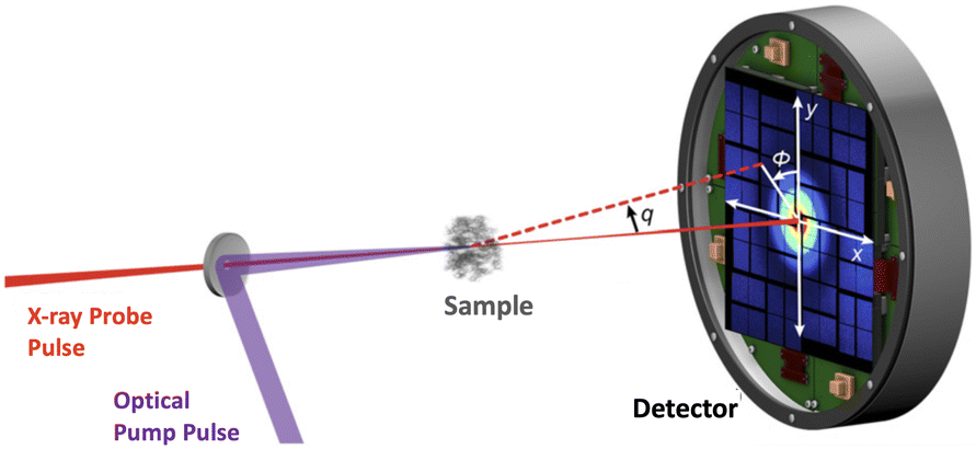 | ||
| Fig. 1 Schematic of the experimental setup in a gas-phase ultrafast X-ray scattering (UXS) experiment. The target molecules are photoexcited by an optical (generally UV or VUV) laser pulse and then probed at different delay-times by an X-ray pulse. Typical X-ray energies are on the order of 8.5 keV, but can be significantly higher. Schematic adapted from ref. 1. | ||
Returning to the specific molecule investigated in this paper, the ultrafast dynamics in CP upon excitation to the 1B2 (ππ*) state has been explored experimentally using time-resolved ionisation mass and photoelectron spectroscopy.17–19 It is thought that the relaxation from the 1B2 state to the ground state occurs through the spectroscopically dark 2A1 state. However, this state has been located theoretically and has been shown to lie above the 1B2 state in the Franck–Condon (FC) region.20,33–35 Consequently, time-resolved experimental studies have invoked conical intersections (CIs) to explain the short time scale dynamics.
The experimental study by Fuß et al. used intense-field ionisation to track the short time (<350 fs) dynamics of CP, suggesting two competing processes for the relaxation of CP.17 Following excitation to the 1B2 state, the authors proposed that the molecule decays to the dark 2A1 state within 37 fs from where two different CIs with the ground state are invoked, associated with two photochemical pericyclic reactions: either an electrocyclisation reaction to form bicyclo[2.1.0]pentene (BP) and tricyclo[2.1.0.02,5]pentane (TP) (71 fs) or a 1,3-sigmatropic hydrogen shift with a time constant of 333 fs, where the hydrogen shift is thought to be dominant. In addition, the long time scale dynamics (time constant of ≈19 ps) on the hot ground state was also observed and ascribed to the thermal back reaction from BP to CP.
Theoretically, the ultrafast dynamics of CP has been explored using the ab initio multiple spawning (AIMS) method using multi-state complete active space second-order perturbation theory (MS-CASPT2) for the electronic structure.20 From these simulations, upon 100% excitation into S1 (1B2) it was observed that torsion around one or both of the carbon–carbon double bonds is essential for reaching the S1/S0 CI seam. Kuhlman et al. associated this torsion motion with the disrotatory mechanism that would occur to form the BP photoproduct, however, the simulations were terminated once the ground state was populated and therefore, no photoproducts were observed.20
In this paper, we investigate the ultrafast dynamics of CP using an ensemble of surface-hopping trajectories to simulate the nonadiabatic transitions and we extend our simulations to include ground state dynamics up to 10 ps in order to locate the formation of photoproducts on the hot ground state. We also explore the sigmatropic hydrogen shift reaction proposed by Fuß et al.,17 which to our knowledge has not been reported previously. In anticipation of upcoming UXS gas-phase experiments, the time-dependent X-ray scattering signal is computed at multiple levels of theory, and the contributions from the different competing pathways are elucidated.
2 Theoretical methods
2.1 Electronic structure theory and dynamics simulations
The electronic structure is calculated at the extended multi-state complete active space second-order perturbation theory (XMS-CASPT2) level,36 using the BAGEL 1.1 software package.37,38 We use the cc-pVDZ basis, a vertical shift of 0.3 Hartree, and the SS-SR contraction scheme. The (4,4) active space consists of 4 electrons in 4 orbitals, with two sets of π and π* orbitals, and the calculations are run with state averaging over the three lowest-lying singlet states (S0, S1, and S2). The resulting XMS(3)-CASPT2(4,4)/cc-pVDZ method is benchmarked against past calculations20,34,35,39 and experimental results18,40 to confirm that it yields sensible results and is the default method in all calculations (with the exceptions clearly sign-posted).The ground state minimum energy geometries of cyclopentadiene and the photoproducts were optimised and the vibrational normal modes determined. The minimum energy conical intersections (MECIs) were located, and potential energy (PE) profiles constructed by linear interpolation in internal coordinates (LIIC) between the ground-state minimum energy geometry and the relevant MECIs and/or ground-state minimum energy geometries of photoproducts. The UV-vis absorption spectrum was calculated using the SHARC software package41 from 104 initial geometries obtained by sampling the Wigner distribution of the ground-state harmonic oscillator at 0 K, with the excitation energy and oscillator strength computed at each geometry. Initial conditions for the nonadiabatic dynamics were sampled using an excitation window of 5.07–5.13 eV, consistent with a laser pulse duration of 70 fs duration at 243 nm.
The nonadiabatic excited state dynamics were simulated using Tully’s fewest switches surface hopping algorithm42 as implemented in the SHARC 2.1 software package41,43,44 interfaced with the BAGEL 1.1 package37,38 for the electronic structure. Granucci and Persico’s energy-based decoherence scheme was used with a decoherence parameter of 0.1 Hartree.45 The excited-state dynamics were propagated with a 0.1 fs time step for the nuclei and an electronic time step of 0.004 fs.
The trajectories were propagated until they reached the ground electronic state, at which point they were propagated for a further 15 fs before being switched to a different method as described below. The reason for this switch is that the (4,4) active space is unstable for some geometries accessed during the dynamics on the hot ground state. A range of density functional theory (DFT) functionals were evaluated against the calculated XMS-CASPT2 PE profiles to identify a suitable functional for the ground-state dynamics, and PBE0/def2-SV(P) was found to produce very similar results to XMS-CASPT2 along the PE ground-state profiles (details of the benchmarking are provided in the ESI†). Therefore, the ground-state trajectories were propagated using PBE0/def2-SV(P) as implemented in Turbomole 7.546 interlinked with Newton-X 2.4.47,48 The final geometries and velocities from the XMS-CASPT2 trajectories were used as the starting point for these ground-state trajectories, which were propagated for 20 ps with a 0.05 fs time step. The smaller integration step accounts for the large kinetic energy on the ground state.
Some further analysis of the ground state chemistry was carried out using DFT with the PBE0 functional49 and the Orca 4.2.1 software package.50 The ground state minima of cyclopentadiene and the photoproducts were re-optimised at the PBE0/def2-TZVP level and the minimum energy path between BP and CP was located using the nudged elastic band (NEB) approach,51 at the PBE0/def2-SVP level. The highest energy geometry along the minimum energy pathway was used as the initial geometry for the optimisations of the transition state geometry between BP and CP. Further, the transition state corresponding to the hydrogen shift was located using the ground state geometry of CP as a starting point in the transition state optimisation. Both transition states were optimised at the PBE0/def2-TZVP level. To validate these transition states, intrinsic reaction coordinate (IRC) pathways were computed for both structures, at the same level of theory as the optimisations, following the reaction coordinate associated with the imaginary frequency to the nearest minimum in the forward and reverse directions.52 These IRC pathways lead to the expected reactant and product for both transition states, confirming the nature of the transition states.
Finally, time constants for the ground state processes were calculated using RRKM theory, evaluating the sum and density of vibrational states classically, in order to compute the rate constant with the following expression,
 | (1) |
 are the vibrational frequencies of the reactant and transition state, respectively, E is the internal energy of the system, E0 is the barrier height and s is the degrees of freedom. Vibrational frequencies and zero-point energies (ZPE), for the reactants and transition states were computed at the PBE0/def2-TZVP level of theory. We approximate the internal energy as the sum of the reactant’s ZPE and the central excitation energy in the excitation window used for the dynamics simulations (5.1 eV).
2.2 Ultrafast X-ray scattering
In this article, we consider the manner in which the photoinduced molecular dynamics manifests itself in ultrafast X-ray scattering. The X-ray probe pulse is given by the photon number intensity, I(t), where t is the time. Incoming X-ray photons carry the angular frequency ω0 and wave vector k0, while the scattered X-ray photons, in turn, have angular frequency ωs and wave vector ks. The scattering vector, q = k0 − ks, is the difference between the incoming and scattered wave vectors and relates to the momentum transfer and the scattering angle. The corresponding scattering operator is.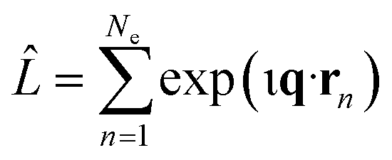 with the sum running over all Ne electrons in the molecule and ι the imaginary unit, q the already defined scattering vector, and rn the real-space coordinate of an electron with index n. An extensive toolbox has been developed to calculate the cross sections for elastic,30,53–55 inelastic,56 and total57,58 X-ray scattering from ab initio electronic wave functions.
When detecting all scattered photons with equal probability irrespective of their energy, also known as total scattering, and invoking the Waller–Hartree approximation (ωs ≈ ω0 and q → ![[q with combining tilde]](https://www.rsc.org/images/entities/b_char_0071_0303.gif) ), the appropriate differential scattering cross section for X-ray scattering is,31,32
), the appropriate differential scattering cross section for X-ray scattering is,31,32
 | (2) |
![[R with combining macron]](https://www.rsc.org/images/entities/b_char_0052_0304.gif) = (R1,…, RNat) of the Nat atomic nuclei. The target molecule enters this expression via its time-dependent wave function,
= (R1,…, RNat) of the Nat atomic nuclei. The target molecule enters this expression via its time-dependent wave function,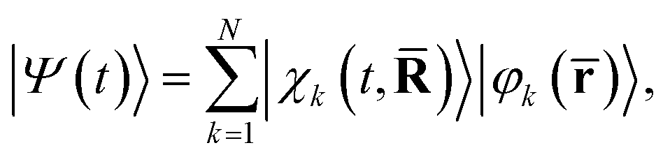 | (3) |
)〉 is the nuclear wave packet on electronic state |φk(![[r with combining macron]](https://www.rsc.org/images/entities/b_char_0072_0304.gif) )〉 which depends parametrically on the nuclear coordinates . We note that the pump–probe delay time is contained within I(t) and that the effect of the pump pulse is embedded in the propagation of the molecular wave function |Ψ(t)〉, with the excitation normally centered at t = 0.
)〉 which depends parametrically on the nuclear coordinates . We note that the pump–probe delay time is contained within I(t) and that the effect of the pump pulse is embedded in the propagation of the molecular wave function |Ψ(t)〉, with the excitation normally centered at t = 0.
In terms of scattering, the key quantity in eqn (2) is the two-electron scattering matrix element, which can be written as,32
 | (4) |
 is a doubly Fourier transformed expectation value of the two-electron density operator,
  ,
, | (5) |
ρji(r1,r2,) = 〈φj()|![[small rho, Greek, circumflex]](https://www.rsc.org/images/entities/i_char_e0b7.gif) (r1,r2)|φi()〉. (r1,r2)|φi()〉. | (6) |
The different components of the scattering in eqn (2) are discussed in detail elsewhere.31,32 The close relationship between the scattering signal and the two-electron density implies that X-ray scattering could potentially constitute a sensitive probe of electron correlation.57–60 Furthermore, cross terms between different electronic states i ≠ j give rise to so-called coherent mixed scattering, which can provide interesting information on electron dynamics and coherences31,61,62 and even electronic transitions at conical intersections.63 However, this component is weak and has not been observed experimentally yet. Instead, we focus on the main contributions, by at least two orders of magnitude, which are given by the diagonal terms i = j.
These dominant diagonal contributions reflect the nuclear dynamics, not the least because core electrons closely track the motion of the nuclei.64,65 The positions of the nuclei are given by the nuclear wave packet |χk(t,)〉, which in the current surface-hopping simulations are represented by an ensemble of equally weighted semiclassical trajectories such that  , where γ(t) is trajectory γ. Another factor in the diagonal terms is the nature of the electronic state.29,53,58 This is significantly weaker than the contribution due to the nuclear geometry, but has recently been observed experimentally.1,25,28
Overall, the scattering can be thought of as having two components, elastic (ωs = ω0) and inelastic (ωs ≠ ω0). The elastic component is proportional to,
 | (7) |
 . The net inelastic scattering Si() can most easily be calculated by subtracting the elastic component from the total scattering,
| Si() = Λii(,) − |Fi(|2. | (8) |
Approximate matrix elements can be calculated using the independent atom model (IAM) originally proposed by Debye.66 This computationally convenient model is widely used across crystallography and is taken as a point of reference in the Results. It treats the target as a set of isolated atoms centered at the positions of the nuclei. The isotropic scattering from each atom is given by tabulated67 atomic form factors, f0α(![[q with combining tilde]](https://www.rsc.org/images/entities/i_char_0071_0303.gif) ), for the elastic scattering, with matching atomic inelastic scattering terms, S0α(). This yields the approximate total scattering in the IAM as,
), for the elastic scattering, with matching atomic inelastic scattering terms, S0α(). This yields the approximate total scattering in the IAM as,
 | (9) |
,) does not have indices since IAM does not account for the electronic state. The sums run over the Nat atoms in the molecule and Rα is the position vector for atom α. Upon inclusion of rotational averaging, the expression becomes, | (10) |
To compute the ab initio scattering signals, as shown in Results section 3, the wave functions were calculated from single point calculations at the XMS(3)-CASPT2(4,4) level with the cc-pVDZ basis set using Cartesian spherical harmonics in the OpenMolcas v22.10 electronic structure software package.70,71
3 Results and discussion
3.1 Electronic structure and potential energy surfaces
The ground state minimum energy geometry of CP consists of a planar ring structure and the ground state electronic configuration in the (4,4) active space is comprised of four electrons in the two π orbitals. At this geometry, the S1 state has a vertical excitation energy of 5.30 eV and is a ππ* state. The S2 state lies ∼1.2 eV above S1 and is composed of approximately a 50% contribution from a doubly excited π → π* transition. The ordering of these excited states and their excitation energies is consistent with previous experimental18,40 and theoretical work,20,34,35,39 where the 1B2 ππ* state is lower in energy than the 2A1 (π)2 → (π*)2 state in the Franck–Condon (FC) region.In the previous experimental work by Fuß et al., a conical intersection (CI) associated with an electrocyclisation reaction to form bicyclo[2.1.0]pentene (BP) was hypothesised17 and Kuhlman et al. found three S1/S0 MECIs at the MS(3)-CASPT2(4,4)/6-31G** level of theory.20 Two of these MECIs correspond to a torsion around one of the double bonds (eth1-MECI and eth2-MECI), and the third is associated with disrotatory motion where both double bonds twist (dis-MECI). All three MECIs located by Kuhlman et al.20 are related to torsion of the ring, and therefore likely to be correlated to the electrocyclisation reaction from CP to BP. Therefore, we optimised each of these three geometries using the XMS(3)-CASPT2(4,4)/cc-pVDZ method employed in our work and all three optimisations converged to a single S1/S0 MECI. The geometry of this MECI, included in Fig. 2, is very similar to eth1-MECI, with torsion around one of the double bonds occurring. This is in agreement with the findings of Santolini et al., who used restricted active space self-consistent field (RASSCF) with a (5,4,5) + 3p active space to optimise these three S1/S0 MECIs and, similarly, only found one geometry.39 Furthermore, their converged S1/S0 MECI structure also had a similar geometry to eth1-MECI. It is worth noting that all three sets of calculations are likely to be consistent in terms of the physical picture that emerges, especially as we find that different regions of the CI seam correlate to different reaction pathways.
 | ||
| Fig. 2 LIIC pathway connecting the S0 minimum energy geometry of CP to the S1/S0 MECI (a) and an extension of this pathway to connect the S1/S0 MECI to the photoproduct, BP (b). Both pathways are computed at the XMS(3)-CASPT2(4,4)/cc-pVDZ level of theory. | ||
To visualise the stretch of the potential energy (PE) surface connecting the ground state minimum energy geometry, in the FC region, to the located S1/S0 MECI, we show the PE LIIC in Fig. 2(a). Along the S1 surface, this pathway has a barrierless transition to a shallow minimum. From this minimum, there is a very small barrier of 0.14 eV to the MECI with the ground state and, therefore, accessing this MECI from the FC region on the S1 surface would be predicted to be relatively facile. In the FC region, the S1 state has ππ* character while S2 possesses a large amount of doubly excited state character. Moving across the PE surface to the central region of the LIIC pathway, the characters of S1 and S2 mix, resulting in both states having partial ππ* and doubly excited state character. This indicates that the coupling between these two states, in this region of the PE surface, is fairly large. As the MECI is approached and the energies of the two states begin to diverge, the character of the two states return to their original character in the FC region.
As the S1/S0 MECI is associated with torsion of the ring, it has a geometry resembling the formation of BP. Therefore, it is reasonable to predict that this MECI lies along the pathway to the formation of the BP photoproduct, which makes this electrocyclisation reaction quite accessible. Thus, the LIIC pathway in Fig. 2(a) was extended to include the pathway from the MECI to BP. The full pathway from CP to BP via the S1/S0 MECI is shown in Fig. 2(b). From the S1/S0 MECI, the pathway is barrierless to BP, and hence, the formation should be readily occurring once this MECI has been traversed.
In addition to a CI associated with the electrocyclisation reaction, Fuß et al. also predicted a CI related to a hydrogen shift reaction, either a 1,2- or 1,3-hydrogen shift, where the H atom migrates from C(5) to either C(1) or C(2), respectively.17 A CI has previously been located for the 1,3-H shift in propene, using CASSCF, and the migrating H is located above C(2) with a bond distance of 1.8 Å.72 Therefore, we applied this bond distance between C(1) and the migrating H to CP and optimised this structure at the XMS(3)-CASPT2(8,8)/cc-pVDZ level. The increased active space includes the two C–H σ orbitals and the two C–H σ* orbitals, as required to describe the migration of H to another C atom. The only MECI geometry that we managed to locate has a much longer bond distance between the C(1) and the migrating H, ∼2.8 Å, and is therefore likely to be associated with H dissociation rather than H migration.
Additionally, we constructed a LIIC pathway from CP to the 1,2-hydrogen shift product of CP, to confirm there was no MECI associated with the 1,2-H shift pathway. These energies were computed at the XMS(3)-CASPT2(8,8)/cc-pVDZ level and the resulting pathway is shown in Fig. 3. Across this pathway, there is a large energy gap between the S1 state and the ground state and there are no regions that resemble an S1/S0 crossing point. Therefore, it seems highly likely that the hydrogen shift reaction is a ground state process that is accessed via the same S1/S0 MECI that leads to the electrocyclisation reaction.
 | ||
| Fig. 3 LIIC pathway connecting the S0 minimum energy geometry of CP to the 1,2-H shift product of CP, computed at the XMS(3)-CASPT2(8,8)/cc-pVDZ level of theory. | ||
3.2 UV-vis absorption spectrum
The UV-vis absorption spectrum was calculated from the ground state ensemble and is shown in Fig. 4.73 The spectrum contains one absorption band with a peak maximum around 5.17 eV (240 nm). The only contributing state to this absorption band is S1 and the maximum of this band is comparable to the vertical excitation energy of S1 in the FC region, which is ascribed to the optically bright ππ* state (1B2). The spectrum also has a small contribution at 6.0–6.2 eV from the dark doubly excited S2, (π)2 → (π*)2, state. | ||
| Fig. 4 UV-vis absorption spectrum of CP simulated at the XMS(3)-CASPT2(4,4)/cc-pVDZ level compared to the experimental spectrum reported by Schalk et al.18 The excitation window (5.07–5.13 eV) used for the nonadiabatic dynamics simulations is shown by the green shaded region on the spectrum. | ||
Compared to the experimental absorption spectrum reported by Schalk et al.,18 also included in Fig. 4, the peak maximum of the calculated spectrum is almost identical to that of the experimental spectrum and the shape of the broad peak is also similar. However, at higher energies, in the region between 5.75 and 6.2 eV, there is an onset of another absorption band in the experimental data, which is absent in the calculations. This absorption is due to the lowest lying n = 3 Rydberg state, which is not included in our active space. The reason for excluding the Rydberg orbitals is that the Rydberg states shift to higher energies as the molecular geometry distorts away from the FC region towards the S1/S0 MECI, and hence, these states are not involved in the dynamics at our chosen excitation wavelength. Finally, the figure shows the excitation window at 5.07–5.13 eV, for the nonadiabatic surface-hopping dynamics simulations, as a green shaded region. This excitation region is used in anticipation of experiments.
3.3 Simulations of excited state and ground state dynamics
Surface hopping excited state dynamics simulations of CP were performed using the excitation window of 5.07–5.13 eV, with ∼480 trajectories started on the bright S1 state. The resulting classical adiabatic populations, shown in Fig. 5, reveal that the excited state population in S1 is quickly transferred to the ground state, as the S1 population decreases by 50% in approximately 75 fs. This time-scale is similar to the AIMS simulations by Kuhlman et al., where the S1 population decreased by 50% in 53 fs.20Fig. 5 also shows a small amount of population transfer (∼5%) to the S2 state in the initial 10 fs. This population transfer takes place in regions where the nonadiabatic coupling between the S1 and S2 states is large, as observed when calculating the LIIC path from the FC region to the S1/S0 MECI in Fig. 2(a). Subsequently, the S2 population returns to S1 when the CI with the ground state is approached. | ||
| Fig. 5 Classical populations of the ground and two excited states, of CP, over the time it takes for the trajectories to populate the ground state. | ||
Finally, Fig. 5 shows a small population ascribed to H-atom dissociation, identified as trajectories associated with dissociation of the H atom on C(5). Since the (4,4) active space used in the simulations does not describe H-dissociation correctly, these trajectories are terminated. In addition, a small number of trajectories crash when they reach nonphysical molecular geometries (including one ring-opening) for which the CASSCF fails to converge. These failed trajectories only make up ∼1% of the total ensemble, and explain why the S1 population does not decay fully to zero at large times.
In order to track the number of trajectories that form the BP structure, we monitor two internal coordinates over the time of the dynamics simulations, the C(1)–C(4) bond distance and the C(1)–C(5)–C(4) bond angle. These two internal coordinates change significantly. Comparing the ground state equilibrium geometries of CP and BP, the C(1)–C(4) bond distance decreases 2.36 → 1.54 Å and the C(1)–C(5)–C(4) bond angle decreases 103.4 → 60.7°, respectively. The C(1)–C(4) bond distance for short and long time-scale dynamics is shown in Fig. 6. In the short time-scale dynamics, up to 250 fs, we see oscillations around the ground-state equilibrium bond distance for the first 50 fs, followed by a splitting in the trajectories at around 75–125 fs, which is in the time frame for the S1 → S0 population transfer (Fig. 5). At 75 fs, when half of the population in S1 has been transferred to S0, the bond distance in most trajectories is in the range of 2 to 2.25 Å, which correlates to the trajectories being in a geometry similar to the S1/S0 MECI, which has a bond distance of 2.06 Å.
 | ||
| Fig. 6 Time dependence of the C(1)–C(4) bond distance during the dynamics simulations. | ||
Fig. 6 also shows the time dependence of the C(1)–C(4) bond distance on longer time-scales, up to 10 ps. From this convolution plot,‡ it can be seen that there is a clear separation, where trajectories are either in a geometry with C(1)–C(4) bond distances centred around ∼1.6 or 2.4 Å, corresponding to BP or CP, respectively. Therefore, from this plot we conclude that there are two possible pathways for the trajectories to follow: one that leads to a CP like geometry and one where the BP photoproduct is formed. In addition, analysis of the trajectories that lead to CP-like geometries on the electronic ground state, reveals hydrogen shift reactions, in agreement with Fuß et al. However, in Fuß’s prediction these two different pathways were accessed via two different S1/S0 CIs.17 In contrast, we have only located one CI seam. Nevertheless, upon examination of the geometry at the point where a hop occurs from S1 to S0, in each of the trajectories, we observe a general trend whereby the geometries that are most similar to the MECI favour the formation of BP on the ground state. Moreover, the geometries, which have a more distorted ring structure compared to the MECI, form CP-like structures and lead to a hydrogen shift on the ground state. However, there is no particular internal coordinate that induces this distortion. It is also worth noting that these hopping geometries still retain a geometry resembling the S1/S0 MECI.
Furthermore, tracking the C(1)–C(4) bond distance over long time-scales, as shown in Fig. 6, we also observe that there is little trajectory density between the two different product bands centred at either 1.6 or 2.4 Å indicating a very small degree of interconversion. In fact, we only observe five trajectories that interconvert, which are attributed to the back reaction from BP to CP on the hot ground state, and this only occurs after 6 ps. Therefore, we approximate the number of trajectories that follow each of the two pathways by using a cutoff central bond distance of 2.0 Å to separate the two geometries. Using this metric, we find that 44% of the trajectories follow the pathway that forms the BP structure, via an electrocyclisation reaction, and 55% of the trajectories follow the CP pathway that leads to a hydrogen shift or H dissociation. This ratio differs to the branching ratio stated by Fuß et al., where 80% followed the hydrogen shift pathway and 20% followed the electrocyclisation pathway leading to BP.17 Although these branching ratios are different, the results are in qualitative agreement with regards to the dominant pathway and the photoproduct.
Tracking the time-dependence of the C(1)–C(5)–C(4) bond angle throughout the simulations produces an almost identical plot to the C(1)–C(4) bond-distance plot shown in Fig. 6. Such a plot is included in the ESI (Fig. S4†). The C(1)–C(5)–C(4) angle exhibits the same distinct difference between the BP and CP geometries and, therefore, we again see two separate bands forming, with the populations centred at 105° and 60°, respectively. Hence, we can calculate the branching ratio between the two pathways using a central cutoff bond angle of 80°, which results in identical branching ratios to those quoted above for the C(1)–C(4) bond distance.
3.4 Transition states and time constants of GS reactions
Our simulations show that there are two distinct pathways that the trajectories follow: either one that leads to a hydrogen shift, where the molecule is in a CP geometry, or one that forms the BP structure via an electrocyclisation reaction. As discussed above, these pathways have very little interconversion on short time scales. Fuß et al. predicted a time constant of 19 ps for the thermal back reaction from BP to recover CP on the hot ground state.17 The current simulations only reach 10 ps, which is insufficient to reliably calculate this time constant. Instead, we estimate the time constant using RRKM theory, which requires that the transition state is identified.To locate the transition state (TS) for the thermal reaction, we first optimise the ground state geometries of both BP and CP at the PBE0/def2-TZVP level of theory. The minimum energy pathway between these two geometries is found using the nudged elastic band approach at the PBE0/def2-SVP level. Calculating the minimum energy pathway allows us to start with a good initial guess geometry for the optimisation of the transition state, by using the highest-energy geometry. The optimised TS structure, computed at the PBE0/def2-TZVP level, contains one imaginary frequency at −347.78 cm−1 which corresponds to the opening and closing of the four-membered ring between C(1) and C(4). To validate that the correct TS has been located, we compute the IRC pathway, which follows the reaction coordinate associated with the imaginary frequency in the forward and reverse directions. The reverse direction pathway leads to the BP minimum and the forward direction leads to the CP minimum, confirming that we have located the correct transition state. The reaction profile for this IRC path is shown in Fig. 7(a) with the energies of the optimised structures shown on the plot relative to the BP minimum. From the BP minimum, there is a relatively large energy barrier of 39.23 kcal mol−1 to overcome for this thermal back reaction to occur from BP to CP.
 | ||
| Fig. 7 Intrinsic reaction coordinate (IRC) pathways, computed at the PBE0/def2-TZVP level of theory, from the transition states to each of the minima for both of the reactions that occur on the ground state: the back reaction from BP to CP (a) and the 1,2-hydrogen shift (b). The energies on the plots correspond to energies of the optimised minima and TS geometries at the PBE0/def2-TZVP level and are shown relative to the structure on the left of each of the plots. | ||
Next, we estimate the time constant for the back reaction using RRKM theory. The sum and density of states are evaluated classically using the vibrational frequencies and zero-point energies (ZPE) of the BP and TS structures, calculated using the PBE0/def2-TZVP level theory. We also approximate the internal energy as the sum of the ZPE of BP plus the central excitation energy (5.1 eV) used in the dynamics simulations. Using these approximations in the RRKM formula yields a time constant τBP = 18.76 ps for the thermal back reaction from BP to CP on the hot ground state. This is almost identical to the 19 ps time constant reported by Fuß et al.17 and is consistent with the five trajectories seen to revert to CP during the 10 ps of simulations. We would expect a larger fraction of the trajectories to revert if the simulations were extended to, say, 20 ps.
In addition to the pathway that forms BP via an electrocyclisation reaction, another pathway involves the molecule in the CP geometry and a hydrogen shift on the hot ground state. Here, Fuß et al. infer the presence of a 1,3-sigmatropic hydrogen shift from the deuterium effect,17 however, throughout our simulations, we only see 1,2-hydrogen shifts occurring on the ground state, although, we do see sequential 1,2-hydrogen shifts in multiple trajectories, where the hydrogen migrates to the carbon atom equivalent to a 1,3-hydrogen shift. Furthermore, these 1,2-hydrogen shifts occur readily in the ensemble of trajectories that follow this pathway. Therefore, to explain this observation, we optimised the transition state between CP and the 1,2-hydrogen shift product at the PBE0/def2-TZVP level of theory. The optimised geometry, shown in Fig. 7(b), contains one imaginary frequency at −1101.48 cm−1. This imaginary frequency corresponds to the migration of the hydrogen from C(5) to C(1), hence displaying a 1,2-hydrogen shift. The transition state was validated by an IRC reaction pathway calculation, shown in Fig. 7(b). The energy barrier for the 1,2-hydrogen shift reaction is 24.28 kcal mol−1, from the CP side, which is about half of the barrier for the back reaction from BP to CP. The difference in energy barriers between the two ground state processes explains why we see the hydrogen migration on shorter time scales compared to back reaction from BP to CP during the simulations.
In this case, we also use RRKM theory to calculate the time constant for the 1,2-hydrogen shift process on the ground state. We use the vibrational frequencies and zero-point energies of the CP and TS structures calculated at the PBE0/def2-TZVP level, noting that the actual geometry on the hot ground state will be different from the ground state equilibrium geometry of CP, and that this is an approximation. This calculation yields the time constant τH = 4.75 ps. In comparison to τBP, the τH is much shorter, which validates our observation that the hydrogen shift occurs much more readily than the back reaction from BP to CP on the hot ground state. However, the 1,2-hydrogen shift in the simulations occurs even faster, at approximately 1 ps. This discrepancy may be due to multiple factors, including the approximation where we have used the geometry of the molecule on the hot ground state as the ground state minimum energy geometry, making the calculated time constant an upper bound on the correct value.
3.5 Ultrafast X-ray scattering
In anticipation of ultrafast X-ray scattering experiments, we have modelled the experimental signals predicted by theory and simulations. First, we examine the dominant signal due to the structural dynamics, which can be modelled at the level of the independent atom model, IAM (see Section 3.5.1 below), and second, we examine the accuracy of IAM and what further information can be extracted via more detailed analysis (Section 3.5.2).The results are shown without the temporal convolution over the X-ray pulse I(t) in eqn (2) because we expect that the experiment will be carried out with X-ray pulses that are quite short in comparison with the time-scale for nuclear dynamics. Furthermore, the signals are shown for 100% excitation. In actual experiments, one optimises the intensity of the pump in the interaction region to maximise the excitation fraction while retaining single-photon excitation and avoiding multiphoton effects, which typically limits the excitation fraction to 1–5%. Signatures of too-high pump intensities include ionisation of the target, which can be identified via a characteristic dip in the small-q signal.5 Finally, for convenience we denote the momentum transfer by q rather than the that acts as a reminder of the Waller–Hartree approximation in the theory section 2.2.
The calculated signals are represented as percent differences to match the experimental signals.74 The percent difference has the advantage that many systematic errors not linked to the excitation are cancelled out. It also emphasizes changes in the target relative the ground state equilibrium and improves the visualization of the signal at large q-values. The basic form of the percent difference signal Δ%I(q,t) is,
 | (11) |
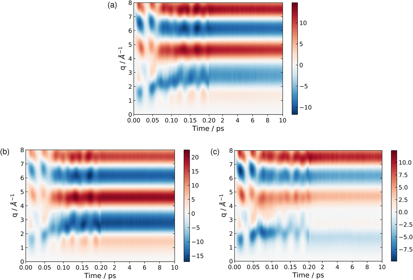 | ||
| Fig. 8 Time-dependent percent difference scattering signals during the dynamics simulations, calculated using the independent atom model (IAM), for the total ensemble of trajectories (a), the BP trajectories (b), and the CP trajectories (c). Note that the scale on the axis changes after 0.2 ps, in order to show more of the detail for the early-time dynamics. | ||
At longer times, 2–10 ps, the signatures of the dynamics in the scattering patterns are less distinct due to more subtle changes in intensity indicative of the dispersion of the wave packet65,76,81 and increasingly statistical (thermalised) dynamics. The scattering in this region can be harvested for information on the overall composition and changes in populations via kinetic models combined with representative scattering patterns for different products.1,5,82 These scattering patterns can be particularly apt at identifying fragmentation of the target at longer times, when present.5,83
 | (12) |
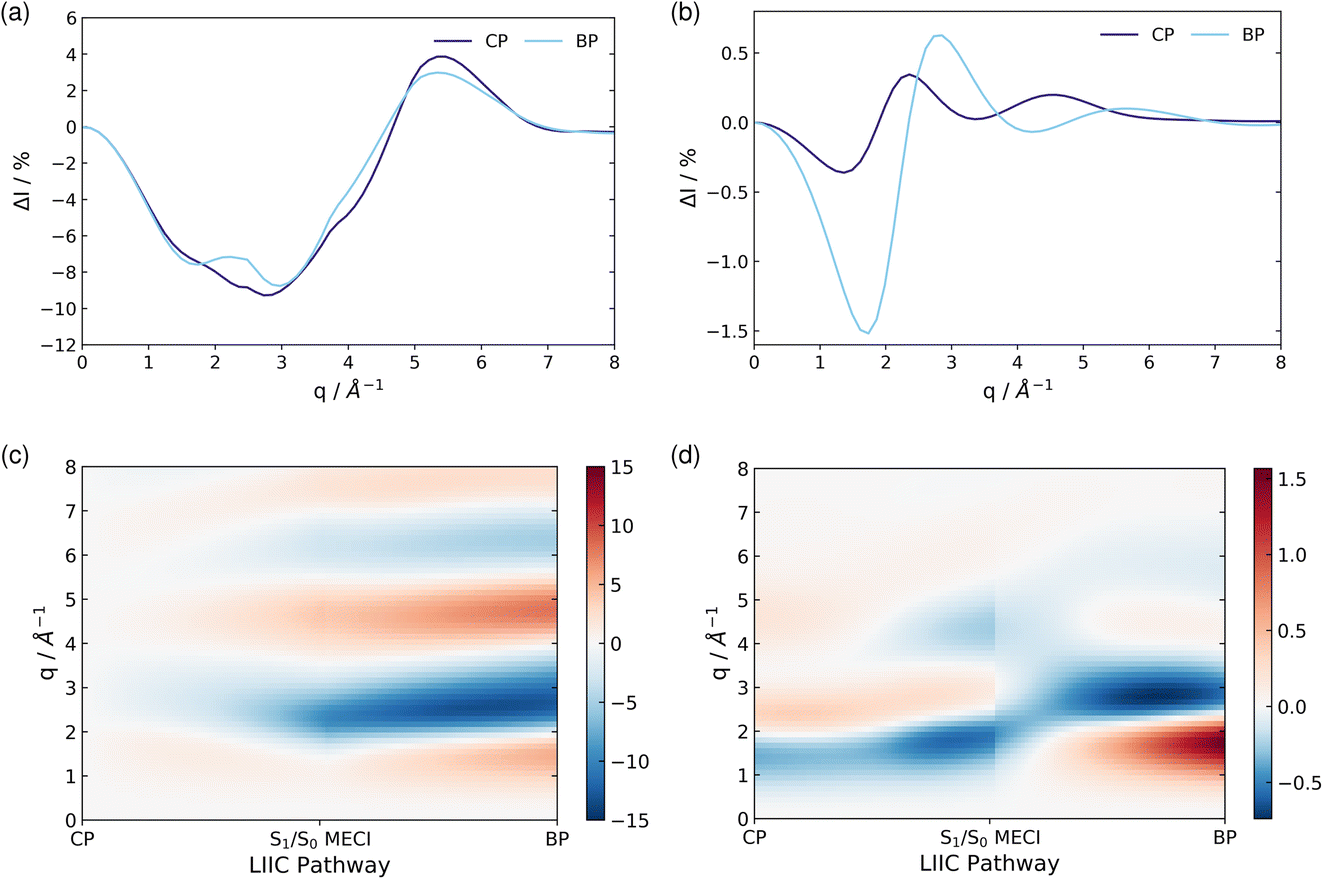 | ||
| Fig. 9 The percent difference between the independent atom model (IAM) and the ab initio scattering signal for the ground electronic state S0, calculated according to eqn (12) at the CP and BP geometries (a), and the percent difference in the scattering from the first excited electronic state S1, as compared to the S0 ground state, calculated using eqn (13), also at the CP and BP geometries (b). The effect of molecular geometry on scattering evaluated using the S0 ground state ab initio scattering and eqn (14), along the entire LIIC pathway (c), and, finally, the difference in scattering from the S1 excited state as compared to the S0 ground state along the LIIC pathway, calculated using eqn (15) (d). | ||
Subsequently, the difference in scattering between the ground electronic state S0 and the first excited state S1 is investigated at fixed geometry for both CP and BP. The difference S0 → S1 is of particular interest since these two electronic states dominate the photoexcited dynamics. The percent difference between S1 and S0 scattering at a specific molecular geometry Rx is calculated using,
 | (13) |
As an approximation of the ab initio scattering across the entire reaction path, we calculate the percent difference signal for the ground state S0 along the LIIC pathway from CP to the S1/S0 MECI, and then onward to BP, as shown in Fig. 9(c). To emphasise the structural dynamics, albeit now using the ab initio S0 scattering rather than the IAM used in Section 3.5.1, we calculate this as,
 | (14) |
Finally, we examine the effect of electronic structure on the scattering by comparing the scattering from the S1 and S0 electronic states along the LIIC path, using the S0 ground state of CP as reference,
 | (15) |
4 Conclusions
Our simulations of photoexcited cyclopentadiene (CP) reveal details of the gas-phase mechanism, including the presence of a conical intersection seam which guides the outcome of the short-time dynamics towards either CP or bicyclo[2.1.0]pentene (BP) depending on how the wave packet enters the conical intersection seam. The simulations also indicate H-atom dissociation as a minor reaction path. At longer times, there appears to be a slower conversion reaction on the electronic ground state, for which we have identified a transition state. The rates predicted by RRKM theory for the ground state process appear to be congruent with both simulations and previous experiments. This also demonstrates a progression from short-time coherent dynamics, governed by dynamics through a conical intersection, to statistical long-time behaviour for the reaction.We have made some initial predictions of the signals one might anticipate in UXS experiments. Although the effect due to the electronic structure is subtle throughout, it is sufficiently large that it might be observed in future high-repetition experiments at LCLS-II that are expected to have good resolution and excellent signal to noise. This would provide an opportunity to detect the electronic state and populations alongside the dynamics, in a similar manner to what was done recently in ultrafast electron diffraction.86 In a broader perspective, one of the advantages of scattering over spectroscopy is that there are no dark states and that these experiments ‘see everything’. However, X-ray scattering is not very sensitive to H-atoms, which scatter weakly. For this specific aspect, electron diffraction has an advantage over X-ray scattering.87 Overall, it is clear that the electronic and nuclear dynamics in photoinduced processes, such as the one simulated here, is complex, and that experimental mapping of the process would benefit greatly from having a range of observables obtained by complementary techniques, for instance by combining the scattering data with time-resolved photoelectron or X-ray absorption spectra.85,88
In terms of studying complex reaction mechanisms in the condensed phase using time-resolved X-ray scattering, we emphasise that much of the original pioneering work on time-resolved scattering was done in the condensed phase where overall cross-sections are higher than in the gas-phase.89–92 With the emergence of XFELs, such experiments have become even more sophisticated, as highlighted in the Introduction.21–23 There have also been quite beautiful demonstrations in the condensed phase of the utility of combining complementary observations, for instance using X-ray emission to track solvent dynamics in scattering experiments.93,94 However, for the time being, the gas-phase experiments have an advantage when it comes to pushing the envelope for the detection of subtle yet information rich effects in the scattering and for exploring novel modes of scattering interactions. This is mainly due to the more structured signal that emerges from the more easily controllable gas target, the absence of an inherently stochastic environment, and ease of modeling. For the time being, therefore, observations of subtle changes in electronic structure and intricate effects related to electronic coherence, are likely to be pursued in the gas-phase. Going forward, the exciting challenge will be to achieve the same measurements in the condensed phase, both via direct measurements in e.g. liquid jets or crystalline samples, and by systematically introducing intermolecular interactions in the gas-phase.95
Conflicts of interest
There are no conflicts to declare.Acknowledgements
LB acknowledges a doctoral studentship from the University of Oxford. AK acknowledges funding from the Engineering and Physical Sciences Research Council (EPSRC UK) via grants EP/V006819 and EP/V049240, and from The Leverhulme Trust via grant RPG-2020-208. This work was also supported by the Department of Energy, Office of Science, Basic Energy Sciences, under award number DE-SC0020276. Finally, LB and AK thank Mr Joe Cooper, Dr Andrés Moreno Carrascosa, and Dr Mats Simmermacher for fruitful discussions regarding the ab initio scattering calculations.Notes and references
- H. Yong, X. Xu, J. M. Ruddock, B. Stankus, A. M. Carrascosa, N. Zotev, D. Bellshaw, W. Du, N. Goff, Y. Chang, S. Boutet, S. Carbajo, J. E. Koglin, M. Liang, J. S. Robinson, A. Kirrander, M. P. Minitti and P. M. Weber, Proc. Natl. Acad. Sci. U. S. A., 2021, 118, e2021714118 CrossRef CAS PubMed.
- W. Fuß, S. Panja, W. E. Schmid and S. A. Trushin, Mol. Phys., 2006, 104, 1133–1143 CrossRef.
- Q. Wang, R. W. Schoenlein, L. A. Peteanu, R. A. Mathies and C. V. Shank, Science, 1994, 266, 422–424 CrossRef CAS PubMed.
- W. G. Dauben, B. Disanayaka, D. J. H. Funhoff, B. Zhou, B. E. Kohler and D. E. Schilke, J. Am. Chem. Soc., 1991, 113, 8367–8374 CrossRef CAS.
- J. M. Ruddock, N. Zotev, B. Stankus, H.-W. Yong, D. Bellshaw, S. Boutet, T. J. Lane, M. Liang, S. Carbajo, W. Du, A. Kirrander, M. P. Minitti and P. M. Weber, Angew. Chem., Int. Ed., 2019, 58, 6371–6375 CrossRef CAS PubMed.
- S. Deb and P. M. Weber, Annu. Rev. Phys. Chem., 2011, 62, 19 CrossRef CAS PubMed.
- S. A. Trushin, S. Diemer, W. Fuß, K. L. Kompa and W. E. Schmid, Phys. Chem. Chem. Phys., 1999, 1, 1431–1440 RSC.
- R. Hoffmann and R. B. Woodward, Acc. Chem. Res., 1968, 1, 17–22 CrossRef CAS.
- R. B. Woodward and R. Hoffmann, Angew. Chem., Int. Ed. Engl., 1969, 8, 781–853 CrossRef CAS.
- J. I. Brauman, L. E. Ellis and E. E. van Tamelen, J. Am. Chem. Soc., 1966, 88, 846–848 CrossRef CAS.
- E. E. Van Tamelen, J. I. Brauman and L. E. Ellis, J. Am. Chem. Soc., 1971, 93, 6145–6151 CrossRef CAS.
- G. D. Andrews and J. E. Baldwin, J. Am. Chem. Soc., 1977, 99, 4851–4853 CrossRef CAS.
- P. Celani, F. Bernardi, M. Olivucci and M. A. Robb, J. Chem. Phys., 1995, 102, 5733–5742 CrossRef CAS.
- M. Squillacote and T. C. Semple, J. Am. Chem. Soc., 1990, 112, 5546–5551 CrossRef CAS.
- M. Olivucci, I. N. Ragazos, F. Bernardi and M. A. Robb, J. Am. Chem. Soc., 1993, 115, 3710–3721 CrossRef CAS.
- P. Chakraborty, Y. Liu, T. Weinacht and S. Matsika, J. Chem. Phys., 2020, 152, 174302 CrossRef CAS PubMed.
- W. Fuß, W. E. Schmid and S. A. Trushin, Chem. Phys., 2005, 316, 225–234 CrossRef.
- O. Schalk, A. E. Boguslavskiy and A. Stolow, J. Phys. Chem. A, 2010, 114, 4058–4064 CrossRef CAS PubMed.
- F. Rudakov and P. M. Weber, J. Phys. Chem. A, 2010, 114, 4501–4506 CrossRef CAS PubMed.
- T. S. Kuhlman, W. J. Glover, T. Mori, K. B. Møller and T. J. Martinez, Faraday Discuss., 2012, 157, 193 RSC.
- E. Nango, A. Royant, M. Kubo, T. Nakane, C. Wickstrand, T. Kimura, T. Tanaka, K. Tono, C. Song, R. Tanaka, T. Arima, A. Yamashita, J. Kobayashi, T. Hosaka, E. Mizohata, P. Nogly, M. Sugahara, D. Nam, T. Nomura, T. Shimamura, D. Im, T. Fujiwara, Y. Yamanaka, B. Jeon, T. Nishizawa, K. Oda, M. Fukuda, R. Andersson, P. Båth, R. Dods, J. Davidsson, S. Matsuoka, S. Kawatake, M. Murata, O. Nureki, S. Owada, T. Kameshima, T. Hatsui, Y. Joti, G. Schertler, M. Yabashi, A.-N. Bondar, J. Standfuss, R. Neutze and S. Iwata, Science, 2016, 354, 1552–1557 CrossRef CAS PubMed.
- J. G. Kim, S. Nozawa, H. Kim, E. H. Choi, T. Sato, T. W. Kim, K. H. Kim, H. Ki, J. Kim, M. Choi, Y. Lee, J. Heo, K. Y. Oang, K. Ichiyanagi, R. Fukaya, J. H. Lee, J. Park, I. Eom, S. H. Chun, S. Kim, M. Kim, T. Katayama, T. Togashi, S. Owada, M. Yabashi, S. J. Lee, S. Lee, C. W. Ahn, D.-S. Ahn, J. Moon, S. Choi, J. Kim, T. Joo, J. Kim, S.-i. Adachi and H. Ihee, Nature, 2020, 582, 520–524 CrossRef CAS PubMed.
- K. Haldrup, G. Levi, E. Biasin, P. Vester, M. G. Laursen, F. Beyer, K. S. Kjær, T. Brandt van Driel, T. Harlang, A. O. Dohn, R. J. Hartsock, S. Nelson, J. M. Glownia, H. T. Lemke, M. Christensen, K. J. Gaffney, N. E. Henriksen, K. B. Møller and M. M. Nielsen, Phys. Rev. Lett., 2019, 122, 063001 CrossRef CAS PubMed.
- M. P. Minitti, J. M. Budarz, A. Kirrander, J. S. Robinson, D. Ratner, T. J. Lane, D. Zhu, J. M. Glownia, M. Kozina, H. T. Lemke, M. Sikorski, Y. Feng, S. Nelson, K. Saita, B. Stankus, T. Northey, J. B. Hastings and P. M. Weber, Phys. Rev. Lett., 2015, 114, 255501 CrossRef CAS PubMed.
- B. Stankus, H. Yong, N. Zotev, J. M. Ruddock, D. Bellshaw, T. J. Lane, M. Liang, S. Boutet, S. Carbajo, J. S. Robinson, W. Du, N. Goff, Y. Chang, J. E. Koglin, M. P. Minitti, A. Kirrander and P. M. Weber, Nat. Chem., 2019, 11, 716–721 CrossRef CAS PubMed.
- B. Stankus, H. Yong, J. Ruddock, L. Ma, A. M. Carrascosa, N. Goff, S. Boutet, X. Xu, N. Zotev, A. Kirrander, M. P. Minitti and P. M. Weber, J. Phys. B: At., Mol. Opt. Phys., 2020, 53, 234004 CrossRef.
- H. Yong, N. Zotev, B. Stankus, J. M. Ruddock, D. Bellshaw, S. Boutet, T. J. Lane, M. Liang, S. Carbajo, J. S. Robinson, W. Du, N. Goff, Y. Chang, J. E. Koglin, M. D. J. Waters, T. I. Sølling, M. P. Minitti, A. Kirrander and P. M. Weber, J. Phys. Chem. Lett., 2018, 9, 6556–6562 CrossRef CAS PubMed.
- H. Yong, N. Zotev, J. M. Ruddock, B. Stankus, M. Simmermacher, A. M. Carrascosa, W. Du, N. Goff, Y. Chang, D. Bellshaw, M. Liang, S. Carbajo, J. E. Koglin, J. S. Robinson, S. Boutet, M. P. Minitti, A. Kirrander and P. M. Weber, Nat. Commun., 2020, 11, 2157 CrossRef CAS PubMed.
- A. Kirrander, J. Chem. Phys., 2012, 137, 154310 CrossRef PubMed.
- A. M. Carrascosa, T. Northey and A. Kirrander, Phys. Chem. Chem. Phys., 2017, 19, 7853–7863 RSC.
- M. Simmermacher, N. E. Henriksen, K. B. Møller, A. Moreno Carrascosa and A. Kirrander, Phys. Rev. Lett., 2019, 122, 073003 CrossRef CAS PubMed.
- M. Simmermacher, N. E. Henriksen, K. B. Møller, A. Moreno Carrascosa and A. Kirrander, J. Chem. Phys., 2019, 151, 174302 CrossRef PubMed.
- H. Nakano, T. Tsuneda, T. Hashimoto and K. Hirao, J. Chem. Phys., 1996, 104, 2312–2320 CrossRef CAS.
- L. Serrano-Andres, M. Merchan, I. Nebot-Gil, B. O. Roos and M. Fulscher, J. Am. Chem. Soc., 1993, 115, 6184–6197 CrossRef CAS.
- Y. J. Bomble, K. W. Sattelmeyer, J. F. Stanton and J. Gauss, J. Chem. Phys., 2004, 121, 5236–5240 CrossRef CAS PubMed.
- T. Shiozaki, W. Győrffy, P. Celani and H.-J. Werner, J. Chem. Phys., 2011, 135, 081106 CrossRef PubMed.
- BAGEL, Brilliantly Advanced General Electronic-structure Library, https://www.nubakery.org under the GNU General Public License Search PubMed.
- T. Shiozaki, Wiley Interdiscip. Rev.: Comput. Mol. Sci., 2018, 8, e1331 Search PubMed.
- V. Santolini, J. P. Malhado, M. A. Robb, M. Garavelli and M. J. Bearpark, Mol. Phys., 2015, 113, 1978–1990 CrossRef CAS.
- R. P. Frueholz, W. M. Flicker, O. A. Mosher and A. Kuppermann, J. Chem. Phys., 1979, 70, 2003–2013 CrossRef CAS.
- S. Mai, M. Richter, M. Heindl, M. F. S. J. Menger, A. Atkins, M. Ruckenbauer, F. Plasser, L. M. Ibele, S. Kropf, M. Oppel, P. Marquetand and L. González, SHARC2.1: Surface Hopping Including Arbitrary Couplings — Program Package for Non-adiabatic Dynamics, 2019, https://sharc-md.org Search PubMed.
- J. C. Tully, J. Chem. Phys., 1990, 93, 1061–1071 CrossRef CAS.
- M. Richter, P. Marquetand, J. González-Vázquez, I. Sola and L. González, J. Chem. Theory Comput., 2011, 7, 1253–1258 CrossRef CAS PubMed.
- S. Mai, P. Marquetand and L. González, Wiley Interdiscip. Rev.: Comput. Mol. Sci., 2018, 8, e1370 Search PubMed.
- G. Granucci and M. Persico, J. Chem. Phys., 2007, 126, 134114 CrossRef PubMed.
- TURBOMOLE V7.5 2020, a development of University of Karlsruhe and Forschungszentrum Karlsruhe GmbH, 1989-2007,TURBOMOLE GmbH, since 2007, available from https://www.turbomole.org Search PubMed.
- M. Barbatti, G. Granucci, M. Ruckenbauer, F. Plasser, R. Crespo-Otero, J. Pittner, M. Persico and H. Lischka, NEWTON-X: A Package for Newtonian Dynamics Close to the Crossing Seam (V. 2.4), 2018, available via the Internet at https://www.newtonx.org Search PubMed.
- M. Barbatti, M. Ruckenbauer, F. Plasser, J. Pittner, G. Granucci, M. Persico and H. Lischka, Wiley Interdiscip. Rev.: Comput. Mol. Sci., 2014, 4, 26–33 CAS.
- C. Adamo and V. Barone, J. Chem. Phys., 1999, 110, 6158–6170 CrossRef CAS.
- F. Neese, Wiley Interdiscip. Rev.: Comput. Mol. Sci., 2012, 2, 73–78 CAS.
- G. Henkelman and H. Jónsson, J. Chem. Phys., 2000, 113, 9978–9985 CrossRef CAS.
- K. Ishida, K. Morokuma and A. Komornicki, J. Chem. Phys., 1977, 66, 2153–2156 CrossRef CAS.
- T. Northey, N. Zotev and A. Kirrander, J. Chem. Theory Comput., 2014, 10, 4911 CrossRef CAS PubMed.
- T. Northey, A. M. Carrascosa, S. Schäfer and A. Kirrander, J. Chem. Phys., 2016, 145, 154304 CrossRef PubMed.
- T. Northey and A. Kirrander, J. Phys. Chem. A, 2019, 123, 3395–3406 CrossRef CAS PubMed.
- A. M. Carrascosa and A. Kirrander, Phys. Chem. Chem. Phys., 2017, 19, 19545–19553 RSC.
- A. M. Carrascosa, H. Yong, D. L. Crittenden, P. M. Weber and A. Kirrander, J. Chem. Theory Comput., 2019, 15, 2836–2846 CrossRef PubMed.
- N. Zotev, A. M. Carrascosa, M. Simmermacher and A. Kirrander, J. Chem. Theory Comput., 2020, 16, 2594–2605 CrossRef CAS PubMed.
- A. M. Carrascosa, J. P. Coe, M. Simmermacher, M. J. Paterson and A. Kirrander, Phys. Chem. Chem. Phys., 2022, 24, 24542–24552 RSC.
- J. P. Coe, A. Moreno Carrascosa, M. Simmermacher, A. Kirrander and M. J. Paterson, J. Chem. Theory Comput., 2022, 18, 6690–6699 CrossRef CAS PubMed.
- M. Simmermacher, A. Kirrander and N. E. Henriksen, Phys. Rev. A, 2020, 102, 052825 CrossRef CAS.
- A. Moreno Carrascosa, M. Yang, H. Yong, L. Ma, A. Kirrander, P. M. Weber and K. Lopata, Faraday Discuss., 2021, 228, 60–81 RSC.
- K. Bennett, M. Kowalewski, J. R. Rouxel and S. Mukamel, Proc. Natl. Acad. Sci. U. S. A., 2018, 115, 6538–6547 CrossRef CAS PubMed.
- A. Kirrander, K. Saita and D. V. Shalashilin, J. Chem. Theory Comput., 2016, 12, 957–967 CrossRef CAS PubMed.
- A. Kirrander and P. M. Weber, Appl. Sci., 2017, 7, 534 CrossRef.
- P. Debye, Ann. Phys., 1915, 351, 809 CrossRef.
- International Tables for Crystallography Volume C: Mathematical, physical and chemical tables, ed. E. Prince, Wiley, 2006 Search PubMed.
- R. F. Stewart, E. R. Davidson and W. T. Simpson, J. Chem. Phys., 1965, 42, 3175 CrossRef CAS.
- R. F. Stewart, J. Bentley and B. Goodman, J. Chem. Phys., 1975, 63, 3786 CrossRef CAS.
- I. Fdez. Galván, M. Vacher, A. Alavi, C. Angeli, F. Aquilante, J. Autschbach, J. J. Bao, S. I. Bokarev, N. A. Bogdanov, R. K. Carlson, L. F. Chibotaru, J. Creutzberg, N. Dattani, M. G. Delcey, S. S. Dong, A. Dreuw, L. Freitag, L. M. Frutos, L. Gagliardi, F. Gendron, A. Giussani, L. González, G. Grell, M. Guo, C. E. Hoyer, M. Johansson, S. Keller, S. Knecht, G. Kovačević, E. Källman, G. Li Manni, M. Lundberg, Y. Ma, S. Mai, J. P. Malhado, P. Å. Malmqvist, P. Marquetand, S. A. Mewes, J. Norell, M. Olivucci, M. Oppel, Q. M. Phung, K. Pierloot, F. Plasser, M. Reiher, A. M. Sand, I. Schapiro, P. Sharma, C. J. Stein, L. K. Sørensen, D. G. Truhlar, M. Ugandi, L. Ungur, A. Valentini, S. Vancoillie, V. Veryazov, O. Weser, T. A. Wesołowski, P.-O. Widmark, S. Wouters, A. Zech, J. P. Zobel and R. Lindh, J. Chem. Theory Comput., 2019, 15, 5925–5964 CrossRef PubMed.
- F. Aquilante, J. Autschbach, A. Baiardi, S. Battaglia, V. A. Borin, L. F. Chibotaru, I. Conti, L. De Vico, M. Delcey, I. Fdez. Galván, N. Ferré, L. Freitag, M. Garavelli, X. Gong, S. Knecht, E. D. Larsson, R. Lindh, M. Lundberg, P. Å. Malmqvist, A. Nenov, J. Norell, M. Odelius, M. Olivucci, T. B. Pedersen, L. Pedraza-González, Q. M. Phung, K. Pierloot, M. Reiher, I. Schapiro, J. Segarra-Martí, F. Segatta, L. Seijo, S. Sen, D.-C. Sergentu, C. J. Stein, L. Ungur, M. Vacher, A. Valentini and V. Veryazov, J. Chem. Phys., 2020, 152, 214117 CrossRef CAS PubMed.
- S. Wilsey and K. N. Houk, J. Am. Chem. Soc., 2000, 122, 2651–2652 CrossRef CAS.
- R. Crespo-Otero and M. Barbatti, Theor. Chem. Acc., 2012, 131, 1237 Search PubMed.
- J. M. Budarz, M. P. Minitti, D. V. Cofer-Shabica, B. Stankus, A. Kirrander, J. B. Hastings and P. M. Weber, J. Phys. B: At., Mol. Opt. Phys., 2016, 49, 034001 CrossRef.
- M. P. Minitti, J. M. Budarz, A. Kirrander, J. Robinson, T. J. Lane, D. Ratner, K. Saita, T. Northey, B. Stankus, V. Cofer-Shabica, J. Hastings and P. M. Weber, Faraday Discuss., 2014, 171, 81 RSC.
- W. O. Razmus, K. Acheson, P. Bucksbaum, M. Centurion, E. Champenois, I. Gabalski, M. C. Hoffman, A. Howard, M.-F. Lin, Y. Liu, P. Nunes, S. Saha, X. Shen, M. Ware, E. M. Warne, T. Weinacht, K. Wilkin, J. Yang, T. J. A. Wolf, A. Kirrander, R. S. Minns and R. Forbes, Phys. Chem. Chem. Phys., 2022, 24, 15416–15427 RSC.
- I. Gabalski, M. Sere, K. Acheson, F. Allum, S. Boutet, G. Dixit, R. Forbes, J. M. Glownia, N. Goff, K. Hegazy, A. J. Howard, M. Liang, M. P. Minitti, R. S. Minns, A. Natan, N. Peard, W. O. Rasmus, R. J. Sension, M. R. Ware, P. M. Weber, N. Werby, T. J. A. Wolf, A. Kirrander and P. H. Bucksbaum, J. Chem. Phys., 2022, 157, 164305 CrossRef CAS PubMed.
- K. Acheson and A. Kirrander, arXiv, 2022, preprint, arXiv:2211.04766, DOI:10.48550/arXiv.2211.04766.
- H. Yong, J. M. Ruddock, B. Stankus, L. Ma, W. Du, N. Goff, Y. Chang, N. Zotev, D. Bellshaw, S. Boutet, S. Carbajo, J. E. Koglin, M. Liang, J. S. Robinson, A. Kirrander, M. P. Minitti and P. M. Weber, J. Chem. Phys., 2019, 151, 084301 CrossRef PubMed.
- H. Yong, A. M. Carrascosa, L. Ma, B. Stankus, M. P. Minitti, A. Kirrander and P. M. Weber, Faraday Discuss., 2021, 228, 104–122 RSC.
- D. Bellshaw, R. S. Minns and A. Kirrander, Phys. Chem. Chem. Phys., 2019, 21, 14226–14237 RSC.
- J. M. Ruddock, H. Yong, B. Stankus, W. Du, N. Goff, Y. Chang, A. Odate, A. M. Carrascosa, D. Bellshaw, N. Zotev, M. Liang, S. Carbajo, J. Koglin, J. S. Robinson, S. Boutet, A. Kirrander, M. P. Minitti and P. M. Weber, Sci. Adv., 2019, 5, eaax6625 CrossRef CAS PubMed.
- Y. Xiong, K. Borne, A. M. Carrascosa, S. K. Saha, K. J. Wilkin, M. Yang, S. Bhattacharyya, K. Chen, W. Du, L. Ma, N. Marshall, J. P. F. Nunes, S. Pathak, Z. Phelps, X. Xu, H. Yong, K. Lopata, P. M. Weber, A. Rudenko, D. Rolles and M. Centurion, Faraday Discuss., 2021, 228, 39–59 RSC.
- B. Stankus, N. Zotev, D. M. Rogers, Y. Gao, A. Odate, A. Kirrander and P. M. Weber, J. Chem. Phys., 2018, 148, 194306 CrossRef PubMed.
- M. Tudorovskaya, R. S. Minns and A. Kirrander, Phys. Chem. Chem. Phys., 2018, 20, 17714–17726 RSC.
- J. Yang, X. Zhu, J. P. F. Nunes, J. K. Yu, R. M. Parrish, T. J. A. Wolf, M. Centurion, M. Gühr, R. Li, Y. Liu, B. Moore, M. Niebuhr, S. Park, X. Shen, S. Weathersby, T. Weinacht, T. J. Martinez and X. Wang, Science, 2020, 368, 885–889 CrossRef CAS PubMed.
- M. Stefanou, K. Saita, D. V. Shalashilin and A. Kirrander, Chem. Phys. Lett., 2017, 683, 300–305 CrossRef CAS.
- C. C. Pemberton, Y. Zhang, K. Saita, A. Kirrander and P. M. Weber, J. Phys. Chem. A, 2015, 119, 8832 CrossRef CAS PubMed.
- R. Neutze, R. Wouts, S. Techert, J. Davidsson, M. Kocsis, A. Kirrander, F. Schotte and M. Wulff, Phys. Rev. Lett., 2001, 87, 195508 CrossRef CAS PubMed.
- J. Davidsson, J. Poulsen, M. Cammarata, P. Georgiou, R. Wouts, G. Katona, F. Jacobson, A. Plech, M. Wulff, G. Nyman and R. Neutze, Phys. Rev. Lett., 2005, 94, 245503 CrossRef.
- A. M. Lindenberg, S. Engemann, K. J. Gaffney, K. Sokolowski-Tinten, J. Larsson, P. B. Hillyard, D. A. Reis, D. M. Fritz, J. Arthur, R. A. Akre, M. J. George, A. Deb, P. H. Bucksbaum, J. Hajdu, D. A. Meyer, M. Nicoul, C. Blome, T. Tschentscher, A. L. Cavalieri, R. W. Falcone, S. H. Lee, R. Pahl, J. Rudati, P. H. Fuoss, A. J. Nelson, P. Krejcik, D. P. Siddons, P. Lorazo and J. B. Hastings, Phys. Rev. Lett., 2008, 100, 135502 CrossRef CAS PubMed.
- J. S. Wark, A. M. Allen, P. C. Ansbro, P. C. Sondhauss, P. H. Bucksbaum, Z. Chang, M. F. DeCamp, H. C. Kapteyn, R. D. Merlin, D. A. Reis, R. W. Falcone, S. L. Johnson, I. Kang, A. Lindenberg, P. A. Heimann, H. A. Padmore, J. Larsson, A. Sjoegren, R. W. Lee, T. Missalla, G. Naylor, K. Scheidt and M. Wulff, Proc. SPIE, 2001, 4143, 26 CrossRef CAS.
- K. Haldrup, W. Gawelda, R. Abela, R. Alonso-Mori, U. Bergmann, A. Bordage, M. Cammarata, S. E. Canton, A. O. Dohn, T. B. van Driel, D. M. Fritz, A. Galler, P. Glatzel, T. Harlang, K. S. Kjær, H. T. Lemke, K. B. Møller, Z. Németh, M. Pápai, N. Sas, J. Uhlig, D. Zhu, G. Vankó, V. Sundström, M. M. Nielsen and C. Bressler, J. Phys. Chem. B, 2016, 120, 1158–1168 CrossRef CAS PubMed.
- R. Alonso-Mori, K. Asa, U. Bergmann, A. S. Brewster, R. Chatterjee, J. K. Cooper, H. M. Frei, F. D. Fuller, E. Goggins, S. Gul, H. Fukuzawa, D. Iablonskyi, M. Ibrahim, T. Katayama, T. Kroll, Y. Kumagai, B. A. McClure, J. Messinger, K. Motomura, K. Nagaya, T. Nishiyama, C. Saracini, Y. Sato, N. K. Sauter, D. Sokaras, T. Takanashi, T. Togashi, K. Ueda, W. W. Weare, T.-C. Weng, M. Yabashi, V. K. Yachandra, I. D. Young, A. Zouni, J. F. Kern and J. Yano, Faraday Discuss., 2016, 194, 621–638 RSC.
- D. A. Horke, H. M. Watts, A. D. Smith, E. Jager, E. Springate, O. Alexander, C. Cacho, R. T. Chapman and R. S. Minns, Phys. Rev. Lett., 2016, 117, 163002 CrossRef CAS PubMed.
Footnotes |
| † Electronic supplementary information (ESI) available. See DOI: https://doi.org/10.1039/d2fd00176d |
| ‡ The bond distances in the trajectories have been convoluted by a narrow Gaussian for the benefit of plotting. |
| This journal is © The Royal Society of Chemistry 2023 |