
 Open Access Article
 This Open Access Article is licensed under a Creative Commons Attribution-Non Commercial 3.0 Unported Licence
Strategies towards enabling lithium metal in batteries: interphases and electrodes
Birger
Horstmann†
 ab,
Jiayan
Shi†
c,
Rachid
Amine†
d,
Martin
Werres†
ab,
Xin
He
e,
Hao
Jia
f,
Florian
Hausen
g,
Isidora
Cekic-Laskovic
h,
Simon
Wiemers-Meyer
i,
Jeffrey
Lopez
j,
Diego
Galvez-Aranda
k,
Florian
Baakes
l,
Dominic
Bresser
am,
Chi-Cheung
Su
c,
Yaobin
Xu
n,
Wu
Xu
f,
Peter
Jakes
g,
Rüdiger-A.
Eichel
g,
Egbert
Figgemeier
i,
Ulrike
Krewer
l,
Jorge M.
Seminario
k,
Perla B.
Balbuena
k,
Chongmin
Wang
n,
Stefano
Passerini
am,
Yang
Shao-Horn
jop,
Martin
Winter
hi,
Khalil
Amine
*cq,
Robert
Kostecki
*e and
Arnulf
Latz
*ab
ab,
Jiayan
Shi†
c,
Rachid
Amine†
d,
Martin
Werres†
ab,
Xin
He
e,
Hao
Jia
f,
Florian
Hausen
g,
Isidora
Cekic-Laskovic
h,
Simon
Wiemers-Meyer
i,
Jeffrey
Lopez
j,
Diego
Galvez-Aranda
k,
Florian
Baakes
l,
Dominic
Bresser
am,
Chi-Cheung
Su
c,
Yaobin
Xu
n,
Wu
Xu
f,
Peter
Jakes
g,
Rüdiger-A.
Eichel
g,
Egbert
Figgemeier
i,
Ulrike
Krewer
l,
Jorge M.
Seminario
k,
Perla B.
Balbuena
k,
Chongmin
Wang
n,
Stefano
Passerini
am,
Yang
Shao-Horn
jop,
Martin
Winter
hi,
Khalil
Amine
*cq,
Robert
Kostecki
*e and
Arnulf
Latz
*ab
aHelmholtz Institute Ulm (HIU), Ulm 89081, Germany. E-mail: arnulf.latz@dlr.de
bGerman Aerospace Center (DLR), Stuttgart 70569, Germany
cChemical Sciences and Engineering Division, Argonne National Laboratory, Lemont, IL 60439, USA. E-mail: amine@anl.gov
dMaterial Sciences Division, Argonne National Laboratory, Lemont, IL 60439, USA
eEnergy Storage and Distributed Resources Division, Lawrence Berkeley National Laboratory (LBNL), Berkeley, CA 94720, USA. E-mail: r_kostecki@lbl.gov
fEnergy and Environment Directorate, Pacific Northwest National Laboratory (PNNL), Richland, WA 99354, USA
gInstitute of Energy and Climate Research IEK-9, Forschungszentrum Jülich GmbH, Jülich, Germany
hHelmholtz-Institute Münster (HI MS), IEK-12, Forschungszentrum Jülich GmbH, Münster, 48149, Germany
iUniversity of Münster, MEET Battery Research Center, Münster, 48149, Germany
jResearch Laboratory of Electronics, Massachusetts Institute of Technology (MIT), Cambridge, Massachusetts 02139, USA
kDepartment of Chemical Engineering, Texas A&M University, College Station, TX 77843, USA
lInstitute for Applied Materials – Electrochemical Technologies (IAM-ET), Karlsruhe Institute of Technology (KIT), Karlsruhe 76021, Germany
mKarlsruhe Institute of Technology (KIT), Karlsruhe 76021, Germany
nEnvironmental Molecular Sciences Laboratory, Pacific Northwest National Laboratory (PNNL), Richland, WA 99354, USA
oDepartment of Mechanical Engineering, Massachusetts Institute of Technology (MIT), Cambridge, MA 02139, USA
pDepartment of Materials Science and Engineering, Massachusetts Institute of Technology (MIT), Cambridge, MA 02139, USA
qMaterial Science and Engineering, Stanford University, Stanford, CA 94305, USA
First published on 29th July 2021
Abstract
Despite the continuous increase in capacity, lithium-ion intercalation batteries are approaching their performance limits. As a result, research is intensifying on next-generation battery technologies. The use of a lithium metal anode promises the highest theoretical energy density and enables use of lithium-free or novel high-energy cathodes. However, the lithium metal anode suffers from poor morphological stability and Coulombic efficiency during cycling, especially in liquid electrolytes. In contrast to solid electrolytes, liquid electrolytes have the advantage of high ionic conductivity and good wetting of the anode, despite the lithium metal volume change during cycling. Rapid capacity fade due to inhomogeneous deposition and dissolution of lithium is the main hindrance to the successful utilization of the lithium metal anode in combination with liquid electrolytes. In this perspective, we discuss how experimental and theoretical insights can provide possible pathways for reversible cycling of two-dimensional lithium metal. Therefore, we discuss improvements in the understanding of lithium metal nucleation, deposition, and stripping on the nanoscale. As the solid–electrolyte interphase (SEI) plays a key role in the lithium morphology, we discuss how the proper SEI design might allow stable cycling. We highlight recent advances in conventional and (localized) highly concentrated electrolytes in view of their respective SEIs. We also discuss artificial interphases and three-dimensional host frameworks, which show prospects of mitigating morphological instabilities and suppressing large shape change on the electrode level.
Broader contextLithium-ion battery technology is driving the current growth in electric vehicle (EV) sales. Despite the tremendous research and development in the field of LIB, it is still not sufficient to meet the demand of new markets such as pure EV. Therefore, there is a need to pursue next-generation electrochemical systems with higher energy densities. The development of high-energy lithium metal electrodes is a promising path in this direction. However, the practical application for such batteries is still challenging due to several obstacles. Lithium tends to grow into inhomogeneous structures, which continuously reduces cell capacity. Such structures can short-circuit the battery, leading to catastrophic failure. The solid–electrolyte interphase, which is forming on the lithium metal electrode, is known to play a key role in their emergence. Here, we give our perspective on the current understanding and design of lithium metal in liquid electrolytes towards stable cycling of lithium metal electrodes. |
1. Introduction
Lithium-ion batteries are currently demonstrating their great potential in helping reach a carbon-neutral society. To obtain this aim, battery design can be adjusted for fueling portable, mobile, and stationary systems. Many positive electrodes have been developed to match different requirements, such as high power and/or long lifetime. By contrast, the negative electrode is basically limited to graphite.1 The use of carbonaceous anodes initiated the successful commercialization of lithium-ion technology in the 1990s, which was honored with the Nobel Prize in Chemistry in 2019.2 Historically, however, the lithium metal electrode came first. It offered a superb energy density, but suffered from safety issues and short cycle life.3In this perspective, recent efforts to overcome aforementioned challenges and to develop durable and safe lithium metal electrodes will be discussed. This direction of research becomes increasingly more important with the advent of high-energy cathodes. Much research is devoted to combining solid electrolytes and lithium metal electrodes.4,5 However, liquid electrolytes as used in lithium-ion batteries offer a high ionic conductivity and can stay in contact with the moving surface of a metal,6 as demonstrated, for example, in commercial zinc metal batteries.7 Moreover, liquid electrolytes for lithium-ion batteries have been studied for decades and have better compatibility with the current manufacturing process than solid-state electrolytes. Therefore, only electrodes and electrode–electrolyte interphases in liquid electrolytes will be discussed in this perspective.
Low Coulombic efficiency constitutes the central problem with lithium metal as an electrode in rechargeable batteries, which can be traced back to its tendency to form non-uniform surface structures on the nano- and macro-scale.8 However, for conventional electrolytes, nano-scale lithium whiskers and porous lithium are observed under typical operation conditions.9,10 The protecting solid–electrolyte interphase (SEI), which forms upon electrolyte reduction, is thought to play an important role in this process.11 Simulations reveal how SEI determines transport and reaction processes on and close to the surface of the negative lithium electrode.12 During cycling, the volume changes of lithium metal lead to rupture and reformation of SEI. Nucleation of whiskers and porous lithium occurs at these SEI cracks.13 Lithium can lose its connection to the current collector during stripping. This so-called dead lithium reduces the battery capacity. Ultimately, a soft short-circuit can lead to cell failure. New diagnostic and simulation tools are supplying insights into the nano-scale processes of nucleation and growth of porous lithium structures, accelerating the progress on lithium metal electrodes (see Fig. 1).
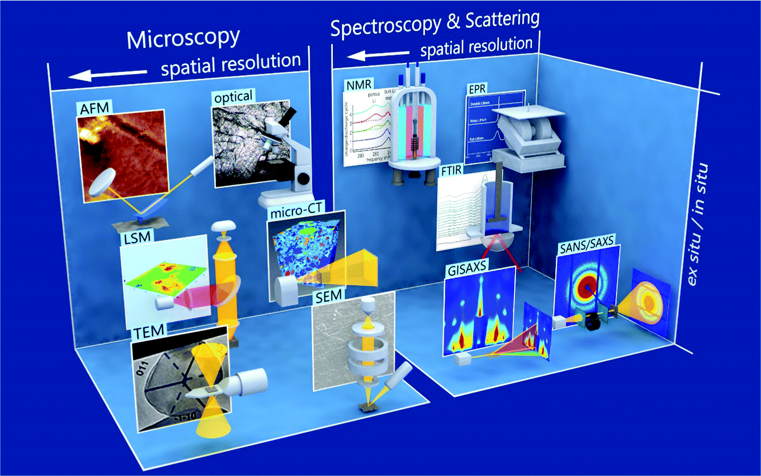 | ||
| Fig. 1 Various methods for studying metallic lithium are schematically presented, along with a typical result, and are divided into microscopic and spectroscopic & scattering techniques. Microscopic techniques include transmission electron microscopy (TEM),14,15 scanning electron microscopy (SEM),9 laser scanning microscopy (LSM),16 micro computed tomography (micro-CT),17 atomic force microscopy (AFM),18,19 and optical microscopy.20 Spectroscopic & scattering techniques include grazing-incidence small angle X-ray scattering (GISAXS),21 small-angle neutron scattering (SANS),22 Fourier-transformed infrared (FTIR),8,23 nuclear magnetic resonance (NMR),24,25 and electron paramagnetic resonance (EPR)24 Spectroscopy. Within the classifications and individual rows, the spatial resolution becomes higher the more left the method is depicted. From bottom to top, it is indicated if a technique is rather used ex situ or in situ. Details on the different characterization techniques are given in Section 5. | ||
Herein, we provide a perspective on how smooth electro-dissolution and -deposition of lithium metal might become feasible. In Section 2, we first categorize different growth modes of lithium metal. Emphasis is given to the correlation between electrochemical test conditions and the observed structures. It is widely recognized that the electrolyte determines the SEI and thereby influences the surface properties of lithium metal.11 Thus, Section 3 emphasizes how the electrolyte should be designed to reach smooth plating of lithium. Common electrolytes used in lithium-ion batteries and novel electrolytes designed for lithium metal batteries are divided into three types: conventional, novel highly concentrated, and localized high concentration electrolytes. They differ in the coordination of lithium with solvent molecules and anions. This affects the reduction products and opens up the field for new interphases on lithium electrodes. Nevertheless, experience from other metal electrodes shows that tuning the surface properties alone is not sufficient to achieve rechargeable electrodes. Therefore, we discuss in Section 4 how lithium electrodes can be engineered to improve cycling performance, such as host structures and surface coatings. The experimental techniques for observing the metal anode structure and its interface with the electrolyte are discussed in Section 5.
2. Classification of structural changes during lithium stripping and plating
The structural changes of the lithium metal anode during cycling are critical for their low performance. We discuss experimentally gained insights of the deposition and stripping processes in common electrolytes, the nucleation of lithium deposits, the growth of high-surface-area structures, and the morphologic changes during stripping. Based on the current theoretical understanding, we classify the observed morphologies and highlight the critical processes responsible for their formation.2.1 Nucleation mechanism
The first step leading to inhomogeneous surface structures upon lithium plating is nucleation, which makes understanding the nucleation process of lithium deposits necessary. Progress has been made towards a clearer picture of how current, potential, and SEI influence the nucleation.Recently, Pei et al. studied the nucleation and growth of lithium deposits on a copper substrate by measuring the voltage profile against Li+/Li and taking ex situ scanning electron microscope (SEM) images of the anode under different plating current densities.26 The voltage profiles showed two distinct overpotential regions: a large negative nucleation overpotential first shows up, followed by a plateau with smaller negative overpotential. This trend illustrates that the nucleation is the harder step during the initial electrodeposition process. During galvanostatic plating, we can distinguish a growth- and nucleation-governed regime. In the growth-governed regime, at low plating currents, a few large deposits grow continuously, which are nucleated in a short initial phase. In the nucleation-governed regime, at large plating currents, many smaller deposits keep on being nucleated. The corresponding SEM images indicate that the size of the lithium deposits is proportional to the inverse of the nucleation overpotential, whereas the density of the lithium deposits is proportional to the cube of the nucleation overpotential, as depicted in Fig. 2a.26 After the initial nucleation phase, the nuclei density remains constant, and the lithium particles grow continuously during galvanostatic plating.26 A large density of nuclei would favor 2D lithium plating. The dependence of the nucleus size on the nucleation overpotential is explained in the context of homogeneous nucleation theory. This theory explains the nucleation barrier with a critical radius that has to be reached before deposits are thermodynamically stable.32 For hemispherical particles, the critical radius is
| rcrit = 2γVM/F|η| | (1) |
![[thin space (1/6-em)]](https://www.rsc.org/images/entities/char_2009.gif) 485 C mol−1 is the Faraday constant, and η [V] is the nucleation overpotential. The critical radius is typically in the order of 1–5 micrometer for lithium plated on copper.26 For a given plated capacity, the nuclei density N times the nuclei volume has to be constant. Thus, the nuclei density scales as N ∼ η3/γ3 (see Fig. 2a).
485 C mol−1 is the Faraday constant, and η [V] is the nucleation overpotential. The critical radius is typically in the order of 1–5 micrometer for lithium plated on copper.26 For a given plated capacity, the nuclei density N times the nuclei volume has to be constant. Thus, the nuclei density scales as N ∼ η3/γ3 (see Fig. 2a).
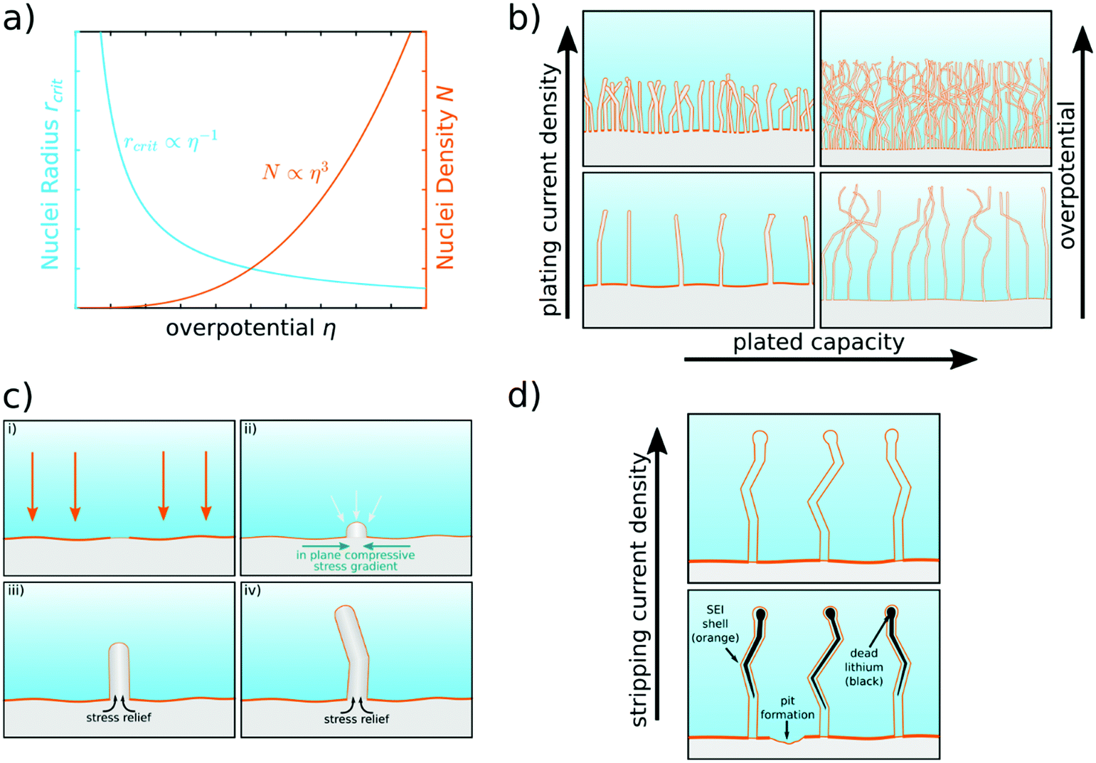 | ||
| Fig. 2 Scheme of lithium nucleation, plating, and stripping behavior. (a) Critical nuclei radius and nuclei density as a function of nucleation overpotential.26 (b) Lithium morphology in dependence on plating current density and plated capacity. Initially, lithium whiskers are formed. Mossy lithium is formed when plating more capacity.27 (c) Nucleation and growth of a single lithium whisker.10 (d) Dissolution of lithium, formation of dead lithium (black),20,28 and pit formation.29 More dead lithium remains for lower stripping current densities.30,31 | ||
As this theory shows, surface energy is the critical material property for the nucleation of inhomogeneous lithium morphologies. However, lithium metal is very reactive such that its bare surface cannot be found within lithium batteries. Thus, surface energy is an effective parameter that depends on various factors. Ely et al. apply the homogeneous nucleation theory and point out that the interfacial energy between lithium metal and the substrate plays an important role in lithium plating.33 This can help to identify suitable materials for current collectors, which are discussed in Section 4 (see, e.g., Zhang et al.34). Moreover, lithium metal forms a passivating layer, the SEI, in contact with the electrolyte, where the surface tension of the SEI represents an effective surface energy for the lithium metal. Biswal et al.35 proved the theory of Ely et al.33 by demonstrating how the surface energy affects the nucleation of inhomogeneous surface structures. The effective surface energy of lithium metal is influenced by SEI composition.35 Fluoroethylene carbonate (FEC) as a functional electrolyte additive is assumed to favor an SEI with increased surface tension and effective surface energy.35 Biswal et al. found that with increasing amounts of FEC, the observed nuclei plated on stainless steel more smoothly and became flatter and slightly larger, which agrees nicely with the prediction from nucleation theory based on the increased surface energy.33
Nucleation is closely linked to defect sites as lithium deposits nucleate heterogeneously. On a microscopic scale, Sanchez et al. showed in operando optical microscopy cells that microstructure features such as grain boundaries act as preferential nucleation sites.36 They suspect that a locally different SEI can be the underlying cause. On a nanoscopic scale, classical molecular dynamics (MD) simulations can help to understand how structural inhomogeneities in the surface affect the nucleation of lithium. Selis et al. performed MD simulations of a lithium metal anode covered by a LiF SEI that is cracked open (see Fig. 3). They showed that at this crack, lithium is reduced preferentially, and lithium does not grow homogeneously.13 This observation highlights that not only the surface tension of SEI but also its mechanical strength is crucial during lithium plating. We conclude that the SEI composition and its mechanical properties strongly influence lithium nucleation.
 | ||
| Fig. 3 Snapshots (time in ps) of dendrite growth under three charging modes: (a) a pulse train of ten Li+ is sent from the cathode to the anode every 4 ps regardless of the rate of reductions at the anode, i.e., cathode driven oxidations; (b) Li+ ion is sent from the cathode to the anode whenever a Li+ is reduced at the anode, i.e., concerted redox anode driven reactions; and (c) Li+ is sent from the cathode every 0.4 ps, keeping the number of ions in the electrolyte always constant, i.e., constant-current cathode driven reactions. Li metal (blue), Li+ (pink, difficult to see), ethylene carbonate and PF6− (green), LiF SEI (yellow).37 | ||
In summary, the nucleation of lithium electrodeposits strongly depends on the applied current density and the resulting overpotential. Homogeneous nucleation is desirable for smooth lithium electrodeposition. The governing parameter for nucleation, the surface energy on the different lithium metal interfaces, can be tuned by the choice of the current collector and by the design of the SEI. Cracks in the SEI represent preferred nucleation sites. Thus, the SEI needs to be adjusted by carefully tailoring the liquid electrolyte via conducting salt, and functional additives choice, as will be explained in Section 3. Nucleation can also be tuned by surface coatings, which will be discussed in Section 4.
2.2 Growth morphology
Experiments studying the lithium metal anode report different forms of heterogeneous lithium morphologies under different conditions. To understand their underlying mechanisms and to find strategies for homogeneous lithium plating, classification and precise terminology are necessary. We distinguish two growth modes according to recent experimental observations:• Lithium metal electrochemically grows as nano-sized whiskers, independent of the applied current density in common electrolytes39 (see Fig. 4a). These whiskers quickly get entangled and form mossy-like, porous lithium (see Fig. 4b).
 | ||
| Fig. 4 Pictures of typical lithium morphologies in conventional electrolytes at different length scales. (a) Standard SEM picture (left) and cryo-SEM picture (right) of lithium whiskers38 – reprinted with permission from Science. Whiskers are needle-like, can have kinks and are ∼100 nm in diameter. (b) SEM picture of mossy lithium27 – reprinted with permission from Electrochimica Acta. Mossy lithium consists of many whiskers that intertwine. (c) In situ snapshot of lithium electrodeposition in a glass capillary cell9 – published by The Royal Society of Chemistry. The transition from mossy lithium to dendritic lithium happens at Sand's time. | ||
• Above a critical current density, fractal-like micron-sized dendrites grow9 (see Fig. 4c). We note that under practical conditions in lithium batteries, dendrites hardly appear.40
Recently, Bai et al. experimentally classified lithium growth modes by taking in situ snapshots of lithium plating for a Li‖Li symmetric cell in a glass capillary at different current densities using conventional electrolytes.9 At a high current density, they observed a transition between the two growth regimes: at early times, mossy-like lithium gets deposited. After a distinct time, rapid, fractal-like dendrite growth occurs (see Fig. 4c).
The fractal-like dendrites were observed to be tip-growing, similar to the behavior known from other metals like Cu and Zn.41,42 The behavior can be explained by electrolyte transport limitations, which occur when the ion concentration at the anode is depleted for current densities exceeding a critical current density at Sand's time.43 Bai et al. observed the onset of dendrite growth clearly at this time.9 Simulations predict elongated dendrites that get more fractal-like when the diffusion limitation becomes more severe.44 The dendrites grow towards the positive electrode and can traverse the full battery cell due to a macroscopic diffusion limitation.
Mossy lithium growth is different from the known dendrite growth behavior of Cu and Zn. It consists of individual whiskers that intertwine27,45 with no clear growth direction20 (see Fig. 2b and 4b). The shape of the whisker tip does not change during growth, indicating root growth.10 This hints at a different underlying mechanism compared to the macroscopically diffusion-limited dendrite growth. This is due to the inherent (electro-)chemical instability of lithium with the electrolyte leading to SEI formation. The slow ion-transport through the SEI leads to a low effective exchange current density, so that the growth is microscopically reaction-limited.9 As in practical batteries, the conditions for diffusion-limited dendrite growth are hard to achieve,40 the focus should lie on understanding and mitigating mossy lithium growth and its precursor, i.e., whisker formation. Therefore, we focus on this deposition morphology here.
To further investigate the deposition of lithium, Kushima et al. directly observed lithium deposition on a gold substrate for low current densities by in situ environmental transmission electron microscopy (TEM) videos.10 Depending on the overpotential, they observed two growth modes. Low overpotentials led to “buds”, which grow from the surface in all directions (see Fig. 2c-ii). For high overpotentials, root growing whiskers were observed (see Fig. 2c-iii). The whiskers follow a characteristic growth scheme. First, the nucleus grows with the square root of time. Second, the nucleus is pushed away from the root, growing rapidly in length, but the diameter stays the same. As a third step, the growth rate decreases. The procedure of fast and slower growth then repeats randomly while kinks may be formed with the start of a new cycle (see Fig. 2c-iv). Whisker growth can also be observed by in situ optical microscopy experiments, as studied by Steiger et al., but due to the small diameter of whiskers, the images are governed by diffraction in this case.20
The two growth modes observed at low current densities are explained to be the result of the competing kinetics of the two reactions of lithium deposition and SEI formation at the electrode's surface.10 The SEI formation plays a crucial role for the growth mode. For graphite electrodes, it was shown that the SEI formation depends on the electrode potential.46,47 Consequently, it is expected that the SEI formation depends on overpotential.48 At low overpotentials, the SEI grows slowly, and lithium-ion transport through the SEI is fast. The lithium metal deposit is covered by a very thin SEI, which does not provide much mechanical resistance to growth. As a result, the lithium metal can grow in all directions pushing the thin SEI forward. At higher overpotentials, on the other hand, the SEI forms rapidly, and a thick SEI will cover the whole electrode surface. In this case, eventually, whiskers form. The favored growth mode is thought to depend on many different factors, such as operating conditions or details about the electrolyte. It is also subject to theoretical works.49
The formation of whiskers is understood to be a stress relaxation process similar to tin whiskers known from lead-free soldering, as illustrated in Fig. 2c.50,51 There, whiskers are formed due to compressive stress.52 In the case of lithium, stress builds up if lithium is inserted underneath a SEI, which does not strongly deform or break. At weak points, the SEI cracks and lithium is pressed out of the bulk. This opens a way to relief the stress by pushing lithium in whisker form through the crack. Lithium atoms move to the weak point due to the high atomic mobility of lithium and fast processes for grain boundary diffusion.53 Wang et al. investigated the role of internal stresses during lithium plating by evaluating a soft substrate against the commonly used copper substrate.54 They found that plating on a soft substrate strongly mitigates lithium whisker growth, and that, instead, the soft substrate wrinkles. This is understood as a stress-releasing mechanism that lightens the internal stress in lithium and lowers the driving force of whisker growth. Thus, a softer substrate is expected to allow for improved stress release.
Recently, cryo-TEM techniques were applied to study the morphology of lithium in its initial stages. Xu et al. observed crystalline whisker-like lithium deposition for all applied current densities in organic carbonate-based electrolyte, in good agreement with the finding that morphological inhomogeneities arise from whisker formation.39 This is in contrast to findings from Wang et al. that an additional amorphous, sheet-like morphology for lithium occurs at low current densities.55 The amorphous Li structure changed to more crystalline and whisker-like structures for longer deposition times and higher current densities in a disorder–order phase transition. The seemingly contradictory results motivate a deeper look into the initial stages of whisker formation.
Whisker growth also occurs for other electroplated metals, e.g., tin, cadmium, and zinc.56–58 These whiskers are single crystals growing from the base.57 However, the situation there is slightly different than for electroplated lithium. High-aspect-ratio whiskers are reported to grow to considerable lengths when storing substrates with the electroplated metal for long periods. As the whiskers could carry large enough currents to induce short circuits, whisker growth is a problem in microelectronics. Research focuses on the long-term formation of whiskers in contrast to lithium whiskers, which grow in the early stages of electrodeposition. The density of whiskers is much larger for plated lithium as well. Still, lithium whisker growth could be related to other metal whiskers. Although whisker growth is not fully understood, the general consensus is that there are necessary conditions for it to occur, such as (1) in-plane compressive stress gradients as a driving force for growth, (2) a fast self-diffusion mechanism for matter transport, and (3) limited surface diffusion, i.e., by a passivating surface layer.59 As stated, there is evidence that lithium whiskers originate from the same underlying features.10,50,54 The much earlier nucleation and fast growth of lithium whiskers could be related to a lower activation energy for self-diffusion of lithium, as lithium has the comparably lowest melting point (180.5 °C).60,61 It is worth noticing that lithium creep is expected over a wide range of battery conditions.60,61 The surface passivating layer is assured by the SEI. While for example tin whiskers are covered by oxide layers, the SEI covering lithium is inhomogeneous in composition, and this will certainly also influence lithium morphology. As the whisker nucleation seems to correlate with surface defects, a mechanically less stable SEI would explain a higher density of lithium whiskers. Sodium metal anodes also suffer severely from whisker growth,62–64 where sodium has an even lower melting point than lithium (97.8 °C). As lithium research is ahead of sodium as anode material, understanding lithium whiskers would also contribute to the future development of sodium metal batteries.
From the comparison of lithium whiskers to other metal whiskers, many research questions arise that upcoming research could address. For tin whiskers, the formation of intermetallic compounds leads to volume expansion and stress build-up.59 What are the contributing factors to the stress build-up for lithium? For tin whiskers, the grain boundary structure underneath the whiskers is known to be prominently V-shaped. While Rulev et al. studied the role of grain boundaries concluding that lithium flows through the grain boundaries to the base of shallow grains pushing these grains upward,53 a clear link to whisker formation is still missing. Does the grain boundary diffusion provide the atom transport to the whisker root, are other creep mechanisms important, or is lithium preferentially deposited at the whisker root?
Similar whisker-like and mossy morphologies of plated lithium are also reported for lithium-ion batteries,65,66 suggesting a universal underlying growth principle. There, lithium electrodeposition on the carbon anode can occur as an unwanted side effect under harsh conditions. This effect, known as plating, enhances the inhomogeneity of electrode structures so that plating should be avoided in lithium-ion batteries.
In literature, there also exist other views on whisker formation. Thermodynamically, electrochemical deposition is closely related to the adsorption/desorption energies of ions at surfaces.67 Surfaces with larger areal packing densities tend to exhibit lower surface energies.67 Magnesium metal batteries are often considered dendrite-free or less prone to dendritic growth.68 According to density functional theory (DFT) studies, the free energy differences between high and low dimensional phases are greater for Mg than for Li, resulting in preferable 2D and 3D growth of Mg compared to 1D growth of Li.69,70 However, research has proven Mg dendrite growth in various electrolytes.71,72 Note that DFT results have to be interpreted carefully, as DFT addresses the equilibrium physics at the lowest length scale and cannot account for out-of-equilibrium dynamics. As mentioned above, in transport-limited scenarios, dendrite formation is anticipated independent of the electrodeposited metal. Thus, it is important to report the applied current densities and to estimate whether the system is transport limited when reporting dendritic growth. Nevertheless, the surface properties of Mg crystals can have a huge impact in mitigating whisker-like structures when the system is not transport limited. Note that with the high melting point of magnesium (650 °C), plastic deformation due to creep is not anticipated at room temperature.
To conclude, the morphology of lithium mainly depends on the applied current density. Dendrites only occur if the current density surpasses the diffusion-limited current density at Sand's time, which seldom occurs in lithium-ion batteries.40 In standard scenarios using conventional electrolytes, mossy lithium occurs, which should not be called dendritic. Mossy lithium is macroscopically reaction limited9 and consists of individual whiskers.27,45 The lithium deposits grow either as buds by surface growth or as whiskers from the root. Root growth is probably a stress relaxation mechanism induced by large compressive stress, which evokes the need for interdisciplinary efforts to understand and mitigate the problem. A precise theoretical explanation of whisker growth would greatly add to the fundamental understanding of metal whiskers, not only for lithium. As the macroscopic reaction limitation is governed by lithium-ion transport through the SEI, the interfacial design is crucial for lithium metal anode operation and will be discussed in Section 3.
2.3 Formation of dead lithium and strategies towards 2D plating
Dendrites are often described as a fatal safety risk for rechargeable lithium metal batteries. As discussed before, however, the practical use of lithium metal is much more hindered by mossy-like, porous lithium growth. During long-term cycling, porous lithium can grow through the cell and lead to a cell short in rare cases. On shorter time scales, the structural inefficiencies always lead to capacity loss because of (1) an enlarged anode surface, which leads to an increased lithium and electrolyte consumption due to SEI formation, and (2) electrochemically inactive lithium evolving during stripping, which is either disconnected from the current collector or only connected through the electronically isolating SEI. Fang et al. performed detailed studies about the quantification of both contributions and concluded that SEI formation is the most important capacity fade factor for very high Coulombic efficiencies, while inactive lithium, commonly referred to as “dead lithium”, is the dominating factor for Coulombic efficiencies below 95%.73 Experiments applying in situ optical microscopy show that inactive lithium evolves as whole structures disconnected from the current collector,10,29 lithium needles are not completely dissolved, and a portion of lithium remains entrapped in the shell of the SEI.20,28 To compensate for the loss of active lithium, pits are formed,29 after the reversible part of the new deposits is stripped. The pits act in the following cycle as preferred nucleation spots and enhance the growth of mossy lithium.29 During cycling, a porous layer of inactive lithium can accumulate. This increases the overpotential and slows down the lithium-ion transport in the liquid electrolyte.74 Higher stripping current densities result in less inactive lithium, as illustrated in Fig. 2d.30,31 Tewari et al. argued that with low overpotentials during stripping, the process is reaction limited, leading to lithium stripping at preferential points, disconnecting other parts from the current collector.30,31 Thus, the plating as well as the stripping current density strongly influences the evolution of the lithium morphology during cycling. For lithium foils, there is a need for strategies to realize 2D plating with as few structure-related inefficiencies as possible to meet the requirements for practical lithium metal batteries of average Coulombic efficiencies well above 99.8%. Other research tries to target the inefficiencies caused by shape change and dead lithium by applying 3D electrode design principles that minimize shape change consequences and try to reactivate dead lithium, and will be discussed in Section 4.Pulse charging has been proposed as a suitable method to compensate for diffusion limitations in the electrolyte.75 As the plating of lithium at practical current densities is reaction limited, or more specifically limited by the lithium ion transport through the SEI, pulse charging is not sufficient to render all inhomogeneities. Rehnlund et al. suggested employing a large density of initial lithium depositions to obtain a homogeneous starting point for further plating.76 Following the idea that large nucleation overpotentials are necessary for large nuclei densities, this work suggested using low salt concentration electrolytes to achieve higher overpotentials and an initial nucleation pulse. Additionally, Rehnlund et al. suggested use of a pulse charging protocol and a supporting salt that does not take part in the reduction reaction.76 The nucleation pulse should lead to instantaneous dense nucleation. With a pulse charging protocol, larger current densities can be applied with fewer effects of transport limitations, as lithium ions can redistribute to regions of lower concentration via diffusion.75 The low salt concentration leads to a smaller diffusion-limiting current, so that transport limitations are reached more easily, and the pulse charging protocol gains importance. The supporting salt should prevent large local electric fields and thus further suppress dendrite growth. By cycling a Li‖Li symmetric cell and using SEM imaging techniques, Rehnlund et al. observed almost no mossy lithium deposition on a micrometer scale after the first plating.76 Extended cycling showed that the suggested routine leads to much less mossy lithium growth compared to the same setup with a higher salt concentration. The mitigation of mossy lithium should imply less inactive lithium, and a more even surface should lead to slower SEI formation. However, for practical use of the applied routine, accurate determination of the Coulombic efficiency, as well as full cell tests, are necessary.
Wang et al. suggested an altered pulse charging protocol for achieving 2D plating.77 They applied an asymmetrical bidirectional current, meaning that a plating pulse is followed by a shorter stripping pulse at the same current. Traditional pulse charging protocols use alternating plating and rest times. With this charging protocol, they observed a more 2D-like anode surface. As structural inhomogeneities such as needles occur, they can dissolve during the applied stripping current, before they evolve too much and cannot be stripped reversely. During the following applied plating current, it takes some time before new structural inhomogeneities nucleate and develop. Thus, the plating current can be applied for a longer time than the stripping current, while preserving a 2D structure. However, the energy loss due to the high stripping current is a major drawback for practical applications.
To conclude, strategies for 2D plating are strongly correlated with the nucleation of lithium deposits. Not only the plating current density and the resulting overpotential, but also the stripping current density influences the reversibility of the reaction. Likely, an optimized cycling protocol alone cannot account for the required Coulombic efficiency. As stated before, SEI strongly affects the nucleation behavior and morphology evolution of lithium and needs to be optimized as well. In the case of whisker-like growth of lithium deposits, strategies for mitigating the internal stress of lithium can be considered to achieve more 2D-like plating.
3. Electrolyte and interphase
Electrolytes play a critical role for the development of lithium metal batteries, as in addition to the basic function, the stabilization of electrode–electrolyte interfaces under aggressive electrochemical conditions represents a crucial task. The incompatibility between the extremely reductive lithium metal and the liquid electrolyte formulations has imposed enormous challenges for practical applications due to the delicate balance between the kinetic stabilization of the lithium metal anode and the thermodynamic stability of the electrolyte. The formation of the SEI is governed by the reduction of electrolyte via corrosion reactions involving lithium and (electro-)chemical reactions of electrolyte components.113.1 Properties of solid–electrolyte interphase (SEI)
By exposure to electrolyte, in general, insoluble corrosion products are generated on the surface of the lithium anode and form an SEI. As frequently stated in Section 2, the SEI is critical to achieve a stable electrochemical cycling of lithium metal. The de-solvation of lithium ions occurs at the interface between the electrolyte and SEI,78 whereas the ionic transport proceeds within the SEI and ends when the lithium ion is reduced at the electrode surface. The efficacy and stability of the SEI depend heavily on its properties, including ionic and electronic conductivity as well as mechanical properties, which are determined by the presence and nature of the SEI components and their relative distribution in this layer.45,79 In line with this, deep insights and knowledge related to ionic transport properties, chemical composition, nanostructure, and mechanical strength of the SEI are crucial for designing long-term cyclable lithium metal electrodes (see Fig. 5).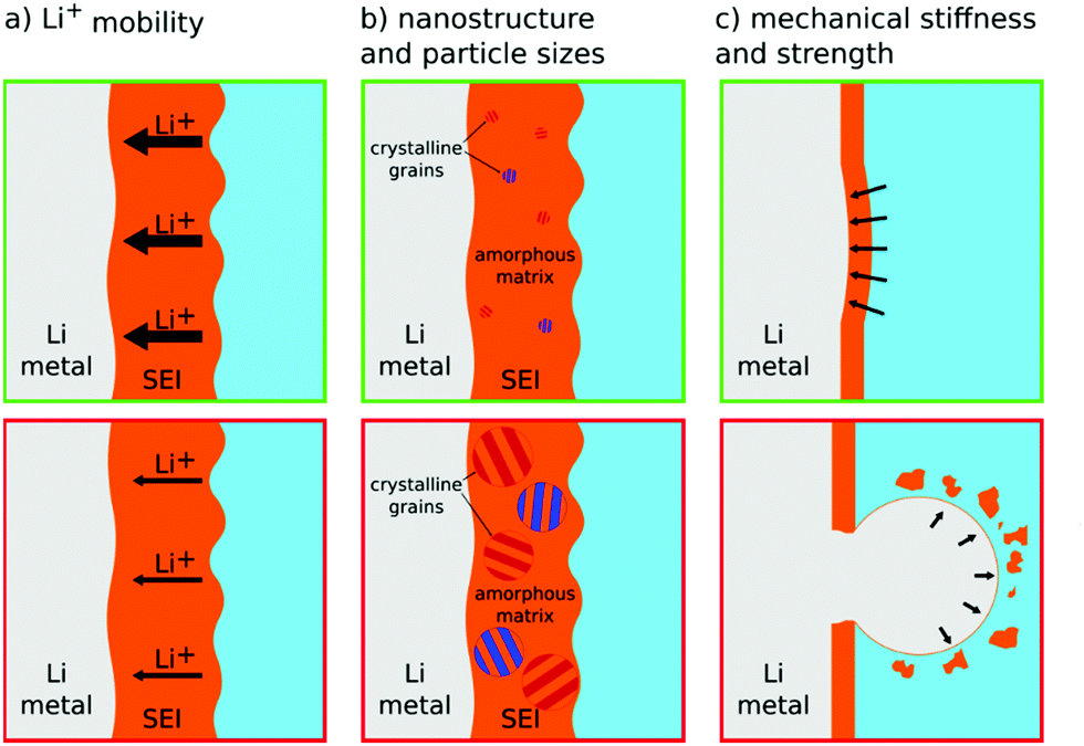 | ||
| Fig. 5 Schematic illustration of how the SEI properties contribute to the lithium metal deposition morphology and how they can positively (top green boxes) or negatively (bottom red boxes) influence smooth electrodeposition. (a) High Li+ mobility is desirable, (b) small crystalline grain size allows for more homogeneity, and (c) a stiff and strong SEI (high elastic modulus and high yield strength) can suppress whisker nucleation by pressing against lithium protrusions, while a SEI with low mechanical strength (low yield strength) breaks and allows whiskers to grow into the electrolyte. | ||
Zhang and coworkers convincingly demonstrated the importance of lithium transport through the SEI for the deposition process.19,88 They present an impressive line of argument: substituting TFSI− with NO3− anions in the electrolyte leads to more Li3N in the SEI, while more Li3N leads to higher ionic mobility in the SEI. The higher ionic mobility corresponds to higher effective macroscopic exchange current densities for plating/stripping (as SEI resistance appears as an effective reaction limitation on the macro-scale). Finally, higher exchange current densities lead to lower overpotentials at galvanostatic conditions or lower applied currents at potentiostatic conditions, thus, a more spherical and less needle-like deposition, as discussed in Section 2.2.10 For the process of lithium stripping, nano-voids, caused by the accumulation of lithium metal vacancies, will form between the SEI layer and lithium.89 Under high rate lithium electro-dissolution or low lithium mobility in the SEI, the aggregation of voids leads to the collapse of the SEI layer.89 This induces an inhomogeneity that favors the growth of lithium whiskers during subsequent plating.
Also as noted in Section 2, the SEI can further increase the effective surface tension of lithium and reduce the tendency to nucleate high-surface-area lithium. Fan et al. calculated the lithium suppression ability for different SEI components, such as LiF, Li2O, and Li2CO3.94 LiF has the highest ability to suppress lithium whiskers, with a value of 5129 eV Å−2.94 Xu and co-authors performed DFT calculations to understand the interface stability and the Li whisker suppression capability of LiF.95 The high surface energy at the Li–LiF interface improves the lithium ion diffusion, relieves interface stress, and promotes a uniform lithium deposition. With high mechanical stability (high adhesion, high elastic modulus, high yield strength), even a thin SEI layer could effectively suppress inhomogeneous lithium growth.79,96 Note that it is untypical for materials to have both, a high elastic modulus and a high yield strength.
Another concern as a consequence of mossy lithium growth, is the formation of electrochemically inactive dead lithium during the stripping process.97 Kramer et al. observed dissolution of lithium needles by in situ optical microscopy.20 Dead lithium remains in the electrolyte after lithium stripping. Notably, the SEI still connects the dead lithium with the substrate and holds it in place. Thus, we expect the mechanical properties of SEI to play some role in the formation of dead lithium, too. A stiff SEI might actually support nucleation of defects in the lithium and favor dead lithium.
3.2 Conventional electrolytes and their interphases
Chemical constituents of SEI are strongly determined by the reductive activation of conducting salts, solvents/co-solvents, functional additives, and impurities present in the electrolyte. Fig. 6 schematically summarizes the most common SEI components and their gaseous and liquid by-products clustered into those that are considered favorable or unfavorable for 2D lithium plating. In this section, we discuss the fundamental mechanisms behind the correlation between electrolyte, SEI, and lithium stripping/plating. Their further elucidation will be a vital route to rationalize and advance the use of liquid electrolytes in functional lithium metal batteries.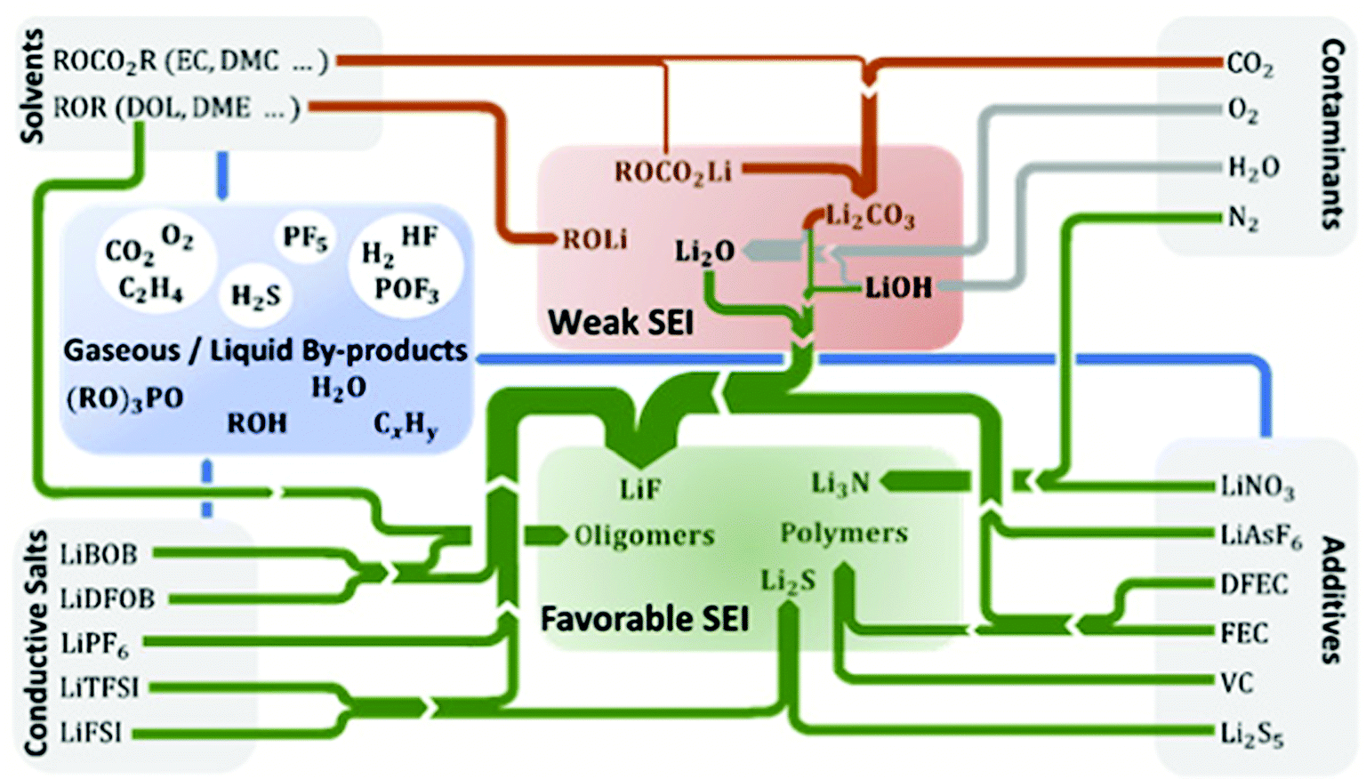 | ||
| Fig. 6 Formation of the most common SEI components and gaseous or liquid degradation products from electrolyte components in lithium metal batteries. The SEI components are clustered into those that are considered to exhibit favorable or weak SEI properties. Reactions of products from the electrolyte components are taken from literature for additives,45,98–105 conducting salts,45,106–109 contaminants,110–114 and solvents.102,106,115,116 The thickness of the arrows corresponds to the number of reactants producing a specific SEI component. | ||
Based on the experimental results mentioned above, LiPF6 with conventional organic carbonate formulations is detrimental to the lithium metal anode, mainly due to poor passivation with this electrolyte. A well-designed lithium metal battery, with a reasonable amount of lithium metal and electrolyte, only lasts for tens of cycles before it consumes all fresh lithium (also known as the “lithium reservoir”).134,135 Due to the reactive nature of lithium metal, once the fresh surface is exposed, the consumption of electrolyte starts. This process is known as an “endless and disappointing” cycle of continuous formation of the SEI, resulting in serious corrosion of the lithium metal anode, increase of cell impedance, and mossy lithium growth. The reduction of electrolyte occurs via electron transfer through the poorly passivating SEI.
Apart from lithium salts, different solvents are also being investigated. In the case of a single-solvent EC-based electrolyte, the main component of the formed SEI is [CH2OCOOLi]2. By adding a co-solvent, the SEI composition becomes more complex.136 Higher EC content in the electrolyte could impact the generation of more lithium alkyl carbonates and polycarbonates in the passivation film, thus enhancing the protection of the lithium metal anode.137 However, alkyl carbonates are generally considered as weak SEI components (Fig. 6), as pointed out by studies of stability and depletion of different solvents (organic carbonates and ethers) on lithium metal.138
Typically, ether-based electrolytes have higher Coulombic efficiency than organic carbonate-based ones as they are generally stabler towards electrochemical reduction compared to commonly used organic carbonates.139 Moreover, ether-based electrolytes are reported to generate mechanically strong SEI films, mitigating the whisker-shaped deposits.50,140 However, few studies compare organic carbonate and ether solvents with the same salt. This is understandable since the field of application for these electrolytes is different. For LiPF6, ethers are not widely used owing to their instability towards the high-voltage (>4.1 V) cathodes117 but are extensively used for sulfur–lithium metal batteries. However, the application of LiPF6 with commonly used ethers in lithium–sulfur batteries is limited because the compatibility between polysulfides and LiPF6 is debatable. For LiFSI and LiTFSI, though organic carbonates are stable towards high voltage, the anodic dissolution of aluminum current collectors introduced by these two salts discourages researchers to investigate the combination of organic carbonates and low-concentration LiFSI/LiTFSI salts. Fang et al. recently published a study on commonly used lithium salts with corresponding solvents.73 For DOL-based electrolyte, the surface film formed on lithium metal includes ionic species (CH3CH2OCH2OLi, HCO2Li, etc.) and oligomers of polydioxolane. The partial polymerization of DOL via the anionic mechanism leads to the formation of oligomers, which are insoluble and adhere to lithium due to the alkoxy (OLi) edge groups.141 Due to the enhanced flexibility of the surface film containing elastomers, compared to the fully ionic surface formed in other classes of electrolytes, the SEI is less prone to fracture. Note that the SEI should not be brittle and have a high surface tension to reduce nucleation of whiskers.33,35 The electrolyte formulation significantly impacts the composition of the SEI, which further influences the morphology of the resulting lithium microstructure.140 Detailed studies of the DOL and DME decomposition, including reaction pathways and activation barriers, were reported based on DFT and ab initio MD simulations, revealing significant changes for the reaction mechanisms with the increase of the salt concentration.142
Since ethers are not commonly used in high-voltage lithium metal batteries, ionic liquids (ILs) are potential candidates for alternative electrolytes and/or electrolyte components for lithium metal batteries owing to favorable physicochemical properties tunable by chemical design of the anion and the cation. This can be combined in numerous ways to tailor relevant physicochemical properties thereof and enhance the compatibility with lithium metal to fulfill the demands of a targeted application.143–149 In fact, ILs have also been successfully demonstrated as an interlayer for optimizing the interface between lithium metal and inorganic solid-state electrolytes, underlining the stability of the Li/IL–electrolyte interface.6
In general, the optimization of the electrolyte and its components may significantly enhance the electrode reaction kinetics facilitated by the enhanced stability and conductivity of an as-formed SEI. This may mitigate the parasitic reactions between the lithium anode and the electrolyte, thus alleviating electrolyte decomposition and by-product generation.137,150 Liquid electrolyte designs are getting exotic, and certain formulations have shown promising results. However, there are challenges still to be addressed, such as control of the mechanical deformation due to the volume variation during charge/discharge cycles and understanding of the morphology of lithium influenced by the SEI.
Among the combination of different components present in the SEI, LiF-rich SEI is able to enhance its self-protective capability153 as well as mechanical stability79,154,155 and to improve significantly the stability of lithium electrodeposition,156 thus enhancing the reversibility of lithium metal electrodes. Instead of directly adding LiF into an electrolyte formulation, fluorinated compounds such as hydrofluoric acid (HF),157 fluoroethylene carbonate (FEC),158,159 1,1,2,2-tetrafluoroethyl-2,2,3,3-tetrafluoropropylether (TTE),160 3,3,3-fluoroethylmethyl carbonate (FEMC),161 1,1,2,2-tetrafluoroethyl-2′,2′,2′-trifluoroethyl ether (HFE),127 and 2-fluoropyridine (2-FP)162 effectively contribute to the formation of an LiF-rich SEI layer, as do the salts lithium bis(fluorosulfonyl)imide (LiFSI),163 lithium-cyclo-difluoromethane1,1-bis(sulfonyl)imide (LiDMSI),164 lithium difluorophosphate (LiDFP),165 lithium hexafluorophosphate (LiPF6),166 lithium tetrafluoroborate (LiBF4),167 and lithium trifluoroacetate (LiTFA)168 as electrolyte components. Addition of a controlled trace amount of water (25–50 ppm) as functional additive for LiPF6-based electrolytes yields a smooth lithium metal deposition and suppressed side reactions as a result of uniform and dense formation of an LiF-rich SEI. The battery is thus able to sustain faster lithium cation diffusion across the electrolyte–electrode interface along grain boundaries.169–171 The synergistic effect of lithium bisoxalatodifluorophosphate (LiDFBOP) and FEC as an additive mixture results in a fluorinated SEI rich in LiF and LixPOyFz, which can further improve the stability and ionic conductivity of the SEI for fast Li+ transportation.172
Apart from the functional electrolyte additives contributing to the LiF-rich SEI, the formation of Li3N as one of the fastest lithium conductors (with an ionic conductivity of 10−3–10−4 S cm−1) results in highly effective SEI layers for fast lithium-ion transfer and lithium deposition.173 The addition of nitrate anions in ether-88 or organic carbonate-based electrolyte,174 even at very low concentration, substantially alters the interfacial chemistry and leads to the formation of a Li3N-rich SEI, thus enabling improved Coulombic efficiencies and spherical lithium electrodeposition.175 Use of LiNO3 as a functional electrolyte additive enables more compact lithium plating and markedly lower overpotential compared to the baseline analogue.90 As a successful alternative, abundant KNO3 positively impacts the reinforcement of the formed SEI due to the synergistic effect of K+ and NO3− ions.176 Present in the electrolyte formulation as an additive mixture, LiNO3 and FEC will both take part in the solvation shell of lithium ions and form a uniform SEI abundant in LiF and LiNxOy, thus resulting in smooth electrodeposition of lithium and enhanced cycling stability.177 Succinic anhydride (SA) affords the formation of a modified SEI layer containing lithium carboxylate on the lithium electrode, which can effectively suppress mossy lithium growth and electrolyte decomposition.178 Reacting with trace amounts of H2O inevitably present in the electrolyte, AlCl3 is involved in the formation of an Al2O3-rich SEI layer, thus preventing undesirable mossy lithium growth and enabling high lithium stripping/plating efficiency of the corresponding cells.179 The synergistic effect of lithium polysulfide and LiNO3 in ether-based electrolyte leads to the formation of an effective and uniform SEI layer with rounded particle morphology.180,181 The functional additive complex Li2S6–P2S5 in DME-based electrolyte enables direct formation of an amorphous single-ion-conducting Li3PS4 layer, sufficient to eliminate the ion depletion and strong electric field buildup at the lithium surface.182 The presence of the trace functional additive tetrapotassium heptaiodobismuthate (K4BiI7) in 1 M LiTFSI in DOL/DME (1:1 by vol) + 1% LiNO3 in the electrolyte results in a robust polycrystalline mosaic-like SEI layer, which yields improved conductivity that facilitates 2D-like lithium deposition and significantly enhances the average Coulombic efficiency of lithium metal anodes.183
The identification and design of novel classes of functional additives with high inhibition capability leading to a controllable passivation layer is one of the most promising paths to enhance the existing lithium metal batteries. Although valuable progress has already been made, great advances still await to be discovered.
3.3 Electrolytes with unique solvation structures
In addition to tuning the composition of the conventional LiPF6–organocarbonate electrolytes, another effective approach to modify the SEI formed on lithium is to tune the solvation structure of the electrolyte.184–186 In the conventional LiPF6-organocarbonate electrolytes, cyclic carbonate solvents, such as EC and PC, have a preference for coordinating to Li+ ions compared with linear carbonate solvents such as DMC, DEC, or EMC (see Fig. 7a).187,188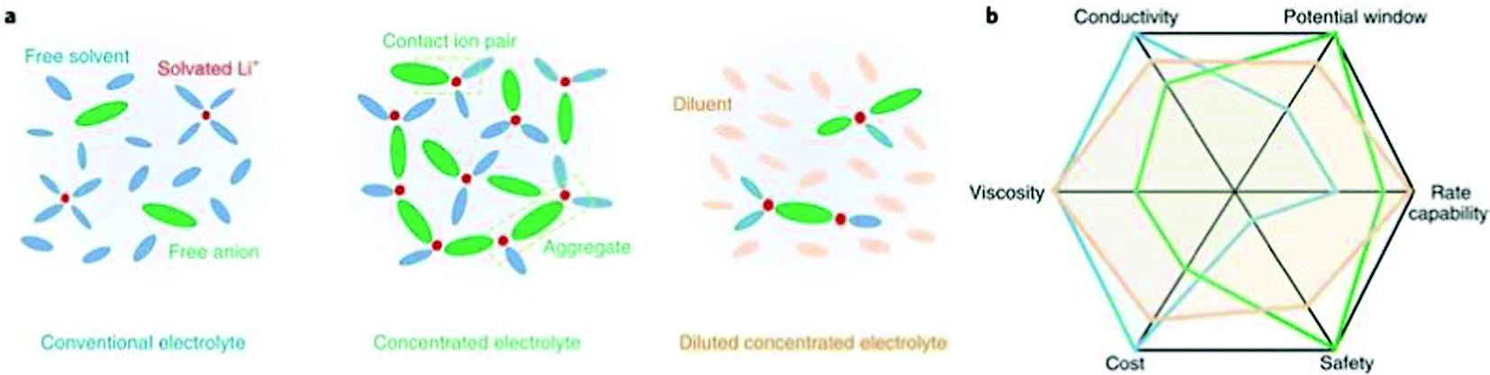 | ||
| Fig. 7 (a) Solvation structures in conventional electrolyte, highly concentrated electrolyte (HCE), and diluted concentrated electrolyte denoted localized high-concentration electrolyte (LHCE). In HCEs, the Li cation coordinates with anion and solvent molecules, which plays a major role in interfacial processes. In LHCEs, the Li ion-anion-solvent complexes are maintained but segregated by an inert solvent called diluent, which is added to reduce the electrolyte viscosity. (b) Spider web chart of electrolyte properties of conventional electrolyte, HCE, and LHCE. Reproduced with permission.185 Copyright 2019 Springer Nature. | ||
The Li+–(cyclic carbonate)n ion sheathes are surrounded by the linear carbonates, which act as diluent in the electrolyte system. In these liquid electrolyte systems, the degrees of lithium conducting salt dissociation are usually within the range of 30–80%. By increasing the lithium salt to a near saturation concentration or by using a mixture of a solvating solvent and a non-solvating solvent, the solvation structure of the electrolyte can be significantly modified. The resulting electrolytes can be categorized as high concentration electrolytes (HCEs) and localized high concentration electrolytes (LHCEs). In these two electrolytes, the ion sheath is composed of not only Li+ and solvating molecules, but also a significant number of anions. In conventional electrolytes, the anions are considered to play a relatively weak part in the SEI formation process due to the electrostatic repulsion between the dissociated anion and the negative electrode. However, by tuning the solvation structure, the Li+–anion−–(solvating solvents)n ion sheath can participate in the SEI formation process as a whole.189,190 Consequently, the SEIs formed in HCEs and LHCEs are composed of a significant amount of anion decomposition products.189,191,192
Nie et al. studied the relationship between the solution structure and the SEI structure.193 In 1.2 M LiPF6–PC electrolyte, the coordination number of PC to Li+ is 4 on average. The primary reduction product in the SEI is lithium propylene dicarbonate (LPDC). At high concentration of LiPF6 in PC (3.0–3.5 M), the coordination number of PC to Li+ is reduced to 3. The electrolyte structure is dominated by contact ion pairs (CIPs) (Li+(PC)3PF6−), and the SEI contains a high concentration of LiF and a low concentration of LPDC. Qian et al. also observed the solvation structure difference in ether-based electrolytes with different concentrations.119 It was discovered that in 1 M LiFSI–DME electrolyte a large fraction of solvent molecules is dissociated, and approximately 60% of the FSI− anions and Li+ cations are uncoordinated. In contrast, only about 3% of the anions are uncoordinated, and 6% of the Li+ cations are fully solvated in the 4 M LiFSI-DME electrolyte. The majority of the ions exist as CIPs and aggregate solvates in the 4 M electrolyte. As a result, the anions react with Li metal and generate a less resistive SEI layer, which has a greater fraction of inorganic components than that formed in the 1 M electrolyte. Ren et al. reported that in LHCEs, FSI− anions enter the Li+ inner solvation shell and the diluent molecules of 1,1,2,2-tetrafluoroethyl 2,2,3,3-tetrafluoropropyl ether (TTE) are outside the solvation sheath.192 The anion incorporation can be assigned to the scarcity of the solvating molecules in LHCE. Because the diluent solvent in LHCE has very weak coordination ability, the introduction of diluent does not increase the coordination solvent for LiFSI. Therefore, the majority of LiFSI is not dissociated, and the anions are incorporated in the solvation sheath. There are more FSI− anions in the Li+ solvation sheath in the LHCEs than those in the HCEs. This solvation sheath structure can promote the reactions between FSI− and lithium metal. Consequently, the SEI layer in the LHCE has higher F atomic ratio and lower C atomic ratio. Based on the previous evidence, it can be concluded that by tuning the solvation structure, the anions are activated in the SEI formation process.
The participation of anions results in significantly changed SEI properties. The SEIs formed in HCEs and LHCEs are generally considered to be ionically more conductive.185,194 The reason can be partially attributed to the formation of highly ionically conductive species such as Li3N and Li2S in SEI.105,173 Moreover, SEIs formed in HCEs and LCHEs are also confirmed to have a unique structure. As revealed by the latest investigation by Cao et al., SEI formed in a typical LHCE exhibits a monolithic amorphous structure, being intrinsically different from the classic layered SEI model.195 Furthermore, SEIs formed in HCEs and LCHEs also offer better protection against solvent corrosion. As revealed by Yamada et al., metallic lithium exhibits extraordinary chemical stability against the electrolyte after adopting the HCE concept.194
With this, it can be concluded that manipulating the structure of the solvation sheath represents a very effective strategy to control the decomposition products at the lithium–electrolyte interface. This strategy, in turn, prominently influences the composition, structure and, consequently, the properties of the SEI.
4. Electrode design
Apart from the governing mechanisms of metal deposition discussed in Section 2, repeated volume change during cycling should also be taken into consideration when studying cell designs. Due to the rapid reaction between the electrolyte and lithium, the growth of porous lithium, e.g., mossy lithium, introduces a huge volume change. Apart from the in situ formed interphases as presented in Section 3 related to electrolyte design, the application of artificial interphases provides a suitable route towards stabilized lithium metal/electrolyte interfaces. Meanwhile, besides the chemical properties of the interphase, the mechanical properties could also be improved. In addition to a stable interphase, the change of volume can be counteracted by offering a “constant-volume” skeleton for lithium deposition.An important question that needs to be answered before we think about potential cell designs is: From an engineering perspective, do the cells die because of the formation of dendritic lithium structures at certain current densities,196 or do they fail because of the mechanical deformation of the separator (due to repeated volume changes) finally letting lithium to pierce through?132 If the answer lies in the former, cell designs should focus more on the deposition kinetics to adjust the mass transfer processes at the interface. If the latter one is correct, that means a “constant-volume” skeleton is indispensable for lithium metal cells, unless the thermodynamic properties of lithium metal or electrolytes could be tuned to make them compatible with each other. Representative studies on the modification of lithium metal cells will be discussed in the following sections.
4.1 Lithium alloys and lithium-free anodes
Conventional lithium foil electrodes suffer from drastic volume changes during the repeated metal plating and stripping process. This behavior is rooted in the thermodynamic incompatibility between liquid organic electrolytes and lithium metal. Due to the reactive nature of metallic lithium, decomposition of electrolytes on fresh deposited Li is inevitable. Therefore, instead of pure lithium, lithium alloys, or lithium-free anodes functioning with an alloying mechanism, have been introduced in beyond lithium-ion batteries, including lithium–sulfur and lithium–air batteries.197,198 Great success was observed with Al–Li199 and other combinations, including In, Zn, Bi, As, and others.200,201 As shown in Fig. 8a, an additional metal cation could be added to the electrolyte to form an alloy.202 Adding supporting metal sources in the electrolyte has been examined in plating multivalent metals such as magnesium.203 Liang et al. observed that by immersing a lithium foil in a metal chloride-containing electrolyte, the lithium foil can be protected by an in situ formed Li-alloy layer and an electronically isolating LiCl layer forms as a by-poduct.200 Another route of alloying is by applying lithiophilic metal substrates, as shown in Fig. 8b. The application of lithiophilic metals such as zinc and gold offers a beneficial effect on the reversible lithium deposition.204 The corresponding alloys LiZn and Li15Au4, which are formed before lithium metal is deposited, do not serve as a passivating layer, but as they lower the overpotential of lithium deposition underneath themselves, they yield a smooth and homogeneous lithium deposition. Lithiophilic metals can be coated on copper substrates205 for the use of lithiated cathode materials and on the surface of lithium metal by means of sputter coating204 to enable the use of non-lithiated cathode materials (or simply to maintain a certain lithium reservoir to balance a non-ideal Coulombic efficiency). The advantage of applying such anodes is that unfavorable thermodynamic properties can be adjusted. However, lithium-free anodes require very high Coulombic efficiencies since there is no excess of lithium that can buffer the irreversible losses.168,206 Otherwise, a pre-lithiation process, such as forming a lithium-excess alloy before cycling, is needed to compensate the lithium loss during the formation of SEI and cycling.207,208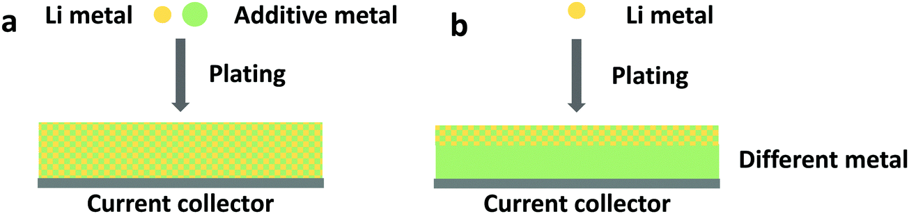 | ||
| Fig. 8 Schematic illustration of lithium free anodes with lithium alloy formation. The alloy may form (a) by introducing an additive metal cation to the electrolyte, or (b) by alloying with a different metal substrate. | ||
Furthermore, recent studies show substantial differences between the reductive electrolyte reactions on lithium and copper surfaces. While these reactions typically form SEI on lithium, preventing further decomposition, copper surfaces have been observed to remain reactive. In the case of copper current collectors only partially covered with lithium metal, the electrolyte reactions on the copper surface lead to an ongoing corrosion of lithium.209,210 This indicates that the copper current collectors might have a strong impact on the Coulombic efficiency, especially during the first electrodeposition step. Similar phenomena are also anticipated in Al–Li, Si–Li, and other alloys. Moreover, though the reactions between electrolytes and alloying anodes are supposed to be milder, enormous volume change seems to be a universal problem of most anodes based on the alloying mechanism. It is reasonable to believe that completely different or even more complex interphases and interfacial behaviors may be introduced by anodes based on alloying mechanisms.
4.2 Artificial interphase design on lithium metal anode
Among all cell designs, the artificial interphase is the most diverse one. Forming an interphase between electrode and electrolyte before cell assembly is a promising way to extend cycling lifetime by utilizing cell design.211 In lithium metal batteries, artificial interphases are typically either polymeric or inorganic in nature, though there are also some examples for composites. The overarching goal of using these coatings at the anode is to decouple the SEI formation from the electrolyte chemistry. This has the potential to ease design constraints on the electrolyte and allow for much more precise control over the ion transport and surface interactions at the electrode–electrolyte interface. In addition, it offers regulation of the mechanical property of the interphase.A number of different polymers have been used as artificial lithium metal interphases, including soft siloxanes212 and supramolecular polymers,213 fluoropolymers,214 polymers with intrinsic microporosity,215 and lithium-containing ionomers.216–219 While many of these studies have revealed improvements to the lithium deposition morphology and increased cycling lifetimes, there remains significant work to be done to understand the origins of these performance improvements. To date, two studies have systematically explored the effects of polymer properties on the lithium electrodeposition process. Both of these studies, one using a classical nucleation model220 and the other using linear stability analysis,221 find that the interfacial energetics described by the polymer surface energy and modulus, together with the lithium transport described by the polymer dielectric constant, ionic conductivity, and transference number control how lithium deposits on the surface. High interfacial energy promotes smooth lithium surfaces and can be obtained either through high modulus or low surface energy or a combination of both. Fast and selective lithium transport through the artificial interphase prevents depletion of Li+ near the electrode–electrolyte interface and further promotes smooth lithium deposition. With these findings, it is now becoming possible to rationally design polymer coatings for high-performance lithium metal batteries.
Inorganic artificial interphase layers have also been studied due to their well-defined nature and high mechanical strength. Some examples of inorganic interphases include alumina,222 Li3PO4,223 and lithium-rich antiperovskites.224 Among inorganic coatings, lithium fluoride has been identified as a key SEI component and so has become the most popular target for synthesis (see Section 3.1). Deposition of LiF coatings has been demonstrated by flowing a F-containing gas over a lithium metal surface225 or through atomic layer deposition (ALD).226 Recent work has found that ex situ-formed artificial LiF interphases do not enhance cycling stability in the same way as in situ-formed LiF-rich SEI does, because they will be broken down during cycling and cannot be repaired by reaction of the fresh lithium surface with the electrolyte,131 as depicted in Fig. 9. This indicates that the intrinsic properties of LiF may not be as important as the holistic stability of SEI (artificial or otherwise). Specifically, the interphase must not form cracks or pinholes during lithium deposition and promote selective transport of Li+ to the electrode to prevent further electrolyte decomposition.
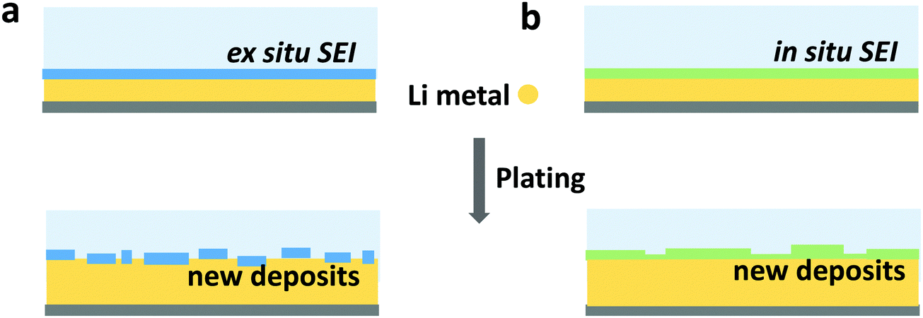 | ||
| Fig. 9 Schematic illustration of an (a) ex situ formed SEI and (b) in situ formed SEI, and the difference after plating Li. Both ex situ and in situ formed SEI can rupture when lithium is deposited inhomogeneously. In (a) the ex situ SEI is irreparably damaged, and a different SEI will form (omitted), while in (b) the in situ SEI can at least partially heal. | ||
Overall, the design of a polymeric and inorganic artificial interphase on a lithium metal anode could suppress the formation of inhomogeneous lithium deposition by changing ion diffusivity, surface energy, and mechanical strength, among other factors. The idea is very close to the liquid electrolyte formulation design. It is of high importance to point out that the in situ-generated SEI components from electrolyte decomposition may show different results in terms of cell performance than the preliminary addition of these components on top of the lithium anode via other techniques. The observed contradictory results require continued investigation into the overall properties of artificial SEI, including but not limited to chemical composition, crystal structure, and mechanical contact between interphases.
4.3 Framework design for lithium metal anode
Apart from modifying the thermodynamic or interfacial properties of the lithium electrode, the use of a smartly designed framework for the lithium deposition is another effective route towards stable cycling of lithium metal. Conductive or non-conductive skeletons not only potentially lower the local current density, but also constrain the volume changes. However, fundamentally speaking, phase separation could happen depending on the depth of cycling, especially when electron-conducting frameworks are used. That means, in the long run, the conductive framework and deposited lithium can detach due to the preferential deposition of lithium on the lithium surface. It is necessary to evaluate the parameters, e.g., interfacial activity, that could possibly postpone or prevent the phase separation to meet practical requirements.As shown in Fig. 10a, lithium prefers being deposited on top of a copper framework instead of on the current collector due to the negligible difference in interfacial activity between the copper current collector and the copper framework. Therefore, the rational design depicted in Fig. 10b, in which lithium deposits easiest at the bottom but harder on the top, has been introduced to form a bottom-up growth of lithium metal. Apart from traditional framework designs, Liang and coworkers introduced a novel electrode design enabling the growth direction horizontal to (and inside) the lithium composite electrode,228 in contrast to the traditional growth of lithium perpendicular to (and only on the surface of) the lithium chip. In their work, a composite lithium electrode was fabricated via a rolling-cutting method in which a layer of lithium foil and a layer of polymer strip were rolled into a cylinder. Subsequently, the as-made cylinder was cut into round disks. As a result, the growth direction of lithium is horizontal to and inside the lithium composite electrode when the cycling conditions are well controlled.
 | ||
| Fig. 10 Growth of lithium metal on the framework with (a) uniform interfacial activity and (b) interfacial activity gradient. The figures are reproduced from ref. 231.227 | ||
In terms of local current density, high-surface-area lithium is preferentially formed during the fast charge transfer process. Therefore, further lowering the local current density and allowing charge re-distribution are beneficial to form a more uniform plating layer. Conductive frameworks are extensively used to increase nucleation sites and enlarge the surface area.229 As a strategy to flatten the lithium electrodeposits, Zhang et al. employed a nitrogen-doped graphene matrix as the current collector.34 The nitrogen-containing functional groups in the matrix are lithiophilic and lead to a homogeneous lithium deposition. A more stable cycling behavior was observed for a nitrogen-doped graphene current collector than for a copper current collector. This was attributed to a smaller local current density due to an enhanced surface area and to a better wettability of lithium on the nitrogen-doped graphene matrix. Use of lithium powder is another method that effectively reduces local current density by the increase of surface area and nucleation sites.230 Carbon is another conducting host structure for lithium. Hu et al. proposed a sponge-like host material formed by three-dimensional (3D) carbon nanotubes (CNTs) for lithium metal anodes, showing good electrochemical stability.231 They took advantage of the high specific surface area in CNTs, which enables a homogeneous charge distribution for lithium. Yuan et al. applied carbon-capsuled soluble alkali metal fluoride and insoluble transition metal fluorides as a skeleton. Apart from being a framework of lithium, mixed metal fluorides release fluorine elements to form stable SEI, which further lowers the charge transfer resistivity.232 A combination design of interfacial activity and cage was also introduced.233 Lithium metal can be plated inside a carbon cage embedded with gold nanoparticles due to its lower nucleation overpotential. The carbon cage not only provides a volume to hold the electrode in place during plating and stripping, but also acts as an artificial surface layer.
The advantage of applying frameworks to lower the local current density and suppress electrode volume change is pronounced. During the initial cycling, deposited lithium has a smoother surface and is accommodated in the 3D skeleton. However, phase separation should always be taken into consideration when electronic conducting frameworks are used. Depending on the depth of cycling, detachment of the conductive framework and deposited lithium can easily happen. Therefore, the interfacial activity of the current collector and framework should be well-designed to allow lithium to always grow inside the framework. Meanwhile, the expansion after formation of porous lithium should be taken into consideration before the design of the skeleton, since, for example, the thickness of 3 mAh lithium may vary widely with different electrolytes and status of cycling. Moreover, introducing frameworks, which are dead weight and volume most of the time, drastically lowers the gravimetric and volumetric capacity of lithium metal cells.234 Right now, obtaining energy densities around 350 Whkg−1 is already difficult.135,234 Therefore, the extra weight and volume of frameworks may hinder the advantages of using lithium metal versus graphite anodes. Delicate engineering and framework designs are needed to outperform the conventional lithium-ion concept.
5. Characterization techniques
Characterizing the interface between metallic lithium and an organic liquid electrolyte requires dedicated methods because of the highly reactive nature of Li. Generally, such diagnostic tools can be classified in microscopy as well as spectroscopy and scattering techniques, as depicted in Fig. 1. While microscopy techniques are typically capable of precisely recording morphology changes during the Li plating and stripping process, spectroscopy tools and scattering techniques are applied to elucidate the chemical nature and (micro)structure of deposited Li and its surrounding area. Within both classifications, there have been increased efforts in recent years to study the metallic Li–liquid interface by in situ tools rather than ex situ. By in situ7Li nuclear magnetic resonance (NMR), the exact formation of microstructures of deposited Li has been investigated.24,25 Similarly, it has been demonstrated by ex situ electron paramagnetic resonance (EPR) that mossy Li, dead Li or bulk metallic Li can be differentiated according to their line shape, enabling localization of lithium growth through the seperator.235 Both techniques are based on specific magnetic properties of the atomic nucleus or the electrons, respectively. Small-angle scattering (SAS) utilizes either X-rays, i.e. ((Grazing-Incidence) small-angle X-ray scattering (GI)SAXS),21 or neutrons (small-angle neutron scattering, SANS).22 While in the case of X-rays, the photons interact with the electrons, i.e. heavier atoms typically exhibit a larger signal, neutrons are elastically scattered by the nucleus and, thus, can be very sensitive even for light elements. However, by employing in situ GISAXS, the size of electrodeposited Li nanoparticles has been analyzed as a function of the applied current density, revealing a raised surface-to-volume ratio at elevated current densitites.21 A detailed analysis of the time-resolved evolution of organic chemical species grown at the interface can be performed by in situ Fourier-transformed infrared spectroscopy (FTIR)8 and dates back to the pioneering work of Auerbach et al. in the early 1990s.141 However, the spatial resolution of most spectroscopic techniques is often limited compared to microscopic tools such as scanning electron microscopy (SEM). Transmission electron microscopy (TEM) with a resolution in the low nanometer range has been applied to study nucleation and growth mechanisms of lithium whiskers in combination with atomic force microscopy (AFM).15 In the case of AFM, the mechanical interactions between a sharp tip and the samples surfaces are probed, and thus, care must be taken not to damage the surface. However, in situ AFM has been employed as an efficient and real-time technique to study the heterogeneous nucleation process, enabling as well local information about mechanical properties of the surface.18,236 Cryogenic TEM is especially useful for preventing damage by the electron beam on Li samples.14,237 Furthermore, TEM can be easily coupled with electron energy loss spectroscopy (EELS) as a spectroscopic method to determine the elemental mapping around the surface in addition.237 Optical microscopy20,29 and laser scanning microscopy (LSM)16 are additional diagnostic tools that allow studying morphological changes in situ and in real-time. However, with a lower resolution compared to AFM, SEM and especially TEM. For microscopic methods, the obtained information is limited to the direct surface. Thereby, important sub-surface effects that might govern the formation of lithium whiskers remain invisible. Employing X-ray microtomography allows to reveal such effects and to obtain a three-dimensional model of the electrode.17 In summary, an in-depth understanding of the lithium deposition and growth mechanisms requires the use of a comprehensive set of complementary in situ/ex situ methods/techniques.6. Conclusion
Lithium metal anode batteries were commercialized much earlier than Li-ion batteries employing carbonaceous negative electrodes.151 Unfortunately, short life span and potential safety issues stalled the development of lithium metal batteries. Nowadays, rechargeable lithium metal batteries are receiving tremendous attention again due to the advantage of high theoretical energy densities. However, rechargeable lithium metal batteries are encountering significant challenges on all fronts, including mechanistic understanding of lithium nucleation/growth, formulation of liquid electrolytes, and design of the interphase and electrode. Ultimately, there are no benchmark systems for rechargeable lithium metal batteries employing liquid electrolytes to date. Interfacial processes and interphase composition may vary significantly in different electrolytes and electrode design.We emphasize the distinction between nanoscale whiskers growing into porous mossy structures, which appear due to macroscopic reaction limitations, and microscale dendrites, which are created by macroscopic transport limitations. Although the failure of rechargeable lithium metal cells is commonly attributed to dendritic lithium upon fast charge, numerous investigations show that internal shorting under quite low currents also occurs. Therefore, the short lifetime should not be simply attributed to dendrite formation. This means that the local current may not be higher than a certain threshold (under mass transfer limitation) to form dendritic structures and cause internal shorting. Therefore, we impose special emphasis on the growth of mossy lithium when a stable interface cannot be achieved due to the inherent incompatibility between the vast majority of liquid electrolytes and lithium metal. Because of the solvent depletion and drastic volume change with the formation of mossy lithium, researchers should reconsider the design of electrolytes, interphases, and the electrode framework.
The instability of the interphase between lithium and the electrolyte during repeated volume change strongly impedes the practical application of lithium metal batteries. It results in the growth of mossy lithium, which occupies large volumes and generates rapid capacity fade during cycling. Scientists are wondering whether we could be lucky enough again to find a magic composition to stabilize the lithium/electrolyte interphase, just like EC-to-graphite. In this perspective, we discussed the correlation between lithium deposition morphology, interphase properties, and electrolyte. The solvation behavior of the solvent molecules was also highlighted since the properties of the interphases they form are heavily influenced by solvation status. Thus, the challenges are not only addressed by adjusting standard liquid electrolytes, but also by inventing highly concentrated electrolytes with unique solvation behavior. The improved in situ-formed SEI might provide an alternative route towards cycle-stable lithium metal electrodes. However, the cost of changing electrolyte formulation could be higher than expected before scale-up, especially for fluorinated solvents. Though electrolyte additives have advantages in terms of cost, the life span of additives is limited, hence limits the long-term cycling. Artificial interphases might provide an alternative route towards cycle-stable lithium metal electrodes. The advantages and challenges of the different interphase design strategies are summarized in Table 1.
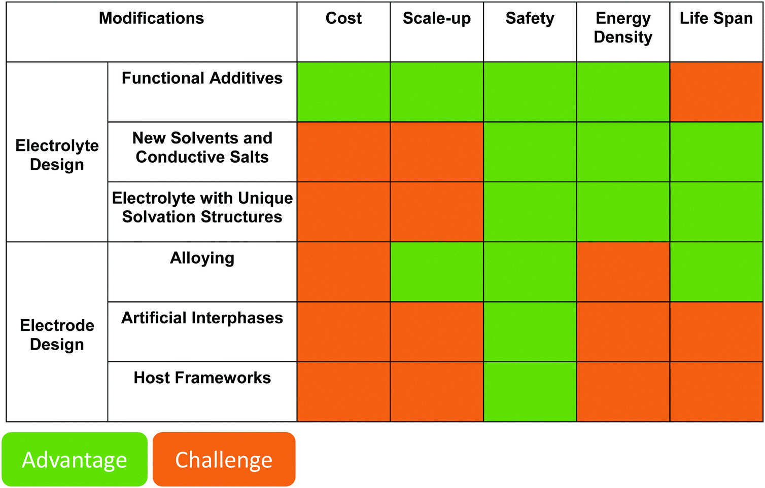
|
Apart from a stable interphase, repeated volume change of metal anodes needs to be taken into consideration. Electrode frameworks offer a choice; however, intrinsic requirements for rechargeable lithium metal batteries with high volumetric and gravimetric energy are limited excess of lithium as well as no dead weight and volume in the anode. Otherwise, such anodes would defeat the main purpose of developing lithium metal batteries, i.e., supplying higher volumetric and gravimetric capacity of graphite anodes. Meanwhile, a framework with reasonable design ensuring life span may be hard to commercialize due to the challenges of lowering cost and scale-up. The results in the literature suggest great challenges are imposed on the lithium metal anode; therefore, a more thorough understanding of current development of lithium metal batteries is needed.
Author contributions
B. H., J. S., R. A., M. W. E., X. H. drafted the outline for this review article. B. H., J. S., R. A., M. WE. organized the writing of this article and harmonized all contributions. B. H. prepared the first draft of Section 1 and the draft of Section 3.1, M. WE. prepared the first draft of Section 2, Fig. 5, and organized the review process, X. H. prepared the first draft of Section 3.1, I. C. L. prepared the first draft of Section 3.2, H. J. prepared the first draft of Section 3.3, J. S. prepared the first draft of Section 4, F. H. prepared the first draft of Section 5 and Fig. 1, R. A. prepared the first draft of Section 6, F. B., U. K. prepared Fig. 6. All authors contributed to the discussion of the manuscript, commented to its development at all stages, added significant thoughts and paragraphs to all chapters, and carefully revised the continuously evolving versions of the manuscript in a highly collaborative manner.Conflicts of interest
The authors declare no competing interests.Acknowledgements
This review article is the result of a concerted approach within the LILLINT research project, jointly funded by the U.S. Department of Energy (DOE) and the German Federal Ministry of Education and Research (BMBF). B. H., M. WE., F. H., I. C. L., S. W.-M., F. B., D. B., P. J., R. E., E. F., E. K., S. P., M. WI., and A. L. acknowledge the financial support within LILLINT project (13XP0225). D. B. and S. P. would like to acknowledge the basic support of the Helmholtz Association. J. L. acknowledges support by an appointment to the Intelligence Community Postdoctoral Research Fellowship Program at the Massachusetts Institute of Technology, administered by Oak Ridge Institute for Science and Education through an interagency agreement between the US Department of Energy and the Office of the Director of National Intelligence. R. A., C. C. S., K. A., H. J., Y. X. W. X., Y. S. H. and C. W. kindly acknowledge the support of the Assistant Secretary for Energy Efficiency and Renewable Energy, Office of Vehicle Technologies of the U.S. Department of Energy under Contracts No. DE-AC02-06CH11357, DE-AC05-76RL01830 under the Advanced Battery Materials Research (BMR) Program and the US-Germany Cooperation on Energy Storage.References
- M. Armand, et al., Lithium-ion batteries – Current state of the art and anticipated developments, J. Power Sources, 2020, 479, 228708, DOI:10.1016/j.jpowsour.2020.228708.
- Nobel Media AB 2021. The Nobel Prize in Chemistry 2019. Fri. 12 Feb 2021 https://www.nobelprize.org/prizes/chemistry/2019/summary/.
- J. B. Goodenough, Evolution of strategies for modern rechargeable batteries, Acc. Chem. Res., 2013, 46, 1053–1061, DOI:10.1021/ar2002705.
- X.-B. Cheng, C.-Z. Zhao, Y.-X. Yao, H. Liu and Q. Zhang, Recent advances in energy chemistry between solid-state electrolyte and safe lithium–metal anodes, Chem, 2019, 5, 74–96, DOI:10.1016/j.chempr.2018.12.002.
- Y. Tang, et al., Electro-chemo-mechanics of lithium in solid state lithium metal batteries, Energy Environ. Sci., 2021, 14, 602–642, 10.1039/D0EE02525A.
- S. A. Pervez, et al., Overcoming the interfacial limitations imposed by the solid–solid interface in solid-state batteries using ionic liquid-based interlayers, Small, 2020, 16, 2000279, DOI:10.1002/smll.202000279.
- N. Borchers, et al., Innovative zinc-based batteries, J. Power Sources, 2021, 484, 229309, DOI:10.1016/j.jpowsour.2020.229309.
- W. Xu, et al., Lithium metal anodes for rechargeable batteries, Energy Environ. Sci., 2014, 7, 513–537, 10.1039/c3ee40795k.
- P. Bai, J. Li, F. R. Brushett and M. Z. Bazant, Transition of lithium growth mechanisms in liquid electrolytes, Energy Environ. Sci., 2016, 9, 3221–3229, 10.1039/c6ee01674j.
- A. Kushima, et al., Liquid cell transmission electron microscopy observation of lithium metal growth and dissolution: Root growth, dead lithium and lithium flotsams, Nano Energy, 2017, 32, 271–279, DOI:10.1016/j.nanoen.2016.12.001.
- X. He, et al., On the passivity of lithium electrodes in liquid electrolyte for secondary batteries, Nat. Rev. Mater., 2021 DOI:10.1038/s41578-021-00345-5.
- A. Wang, S. Kadam, H. Li, S. Shi and Y. Qi, Review on modeling of the anode solid electrolyte interphase (SEI) for lithium-ion batteries, npj Comput. Mater., 2018, 4, 15, DOI:10.1038/s41524-018-0064-0.
- L. A. Selis and J. M. Seminario, Dendrite formation in silicon anodes of lithium-ion batteries, RSC Adv., 2018, 8, 5255–5267, 10.1039/c7ra12690e.
- X. Wang, et al., New insights on the structure of electrochemically deposited lithium metal and its solid electrolyte interphases via cryogenic TEM, Nano Lett., 2017, 17, 7606–7612, DOI:10.1021/acs.nanolett.7b03606.
- Y. He, et al., Origin of lithium whisker formation and growth under stress, Nat. Nanotechnol., 2019, 14, 1042–1047, DOI:10.1038/s41565-019-0558-z.
- K. Nishikawa, et al., In situ observation of dendrite growth of electrodeposited Li metal, J. Electrochem. Soc., 2010, 157, 1212–1217, DOI:10.1149/1.3486468.
- K. J. Harry, D. T. Hallinan, D. Y. Parkinson, A. A. MacDowell and N. P. Balsara, Detection of subsurface structures underneath dendrites formed on cycled lithium metal electrodes, Nat. Mater., 2014, 13, 69–73, DOI:10.1038/nmat3793.
- M. Kitta and H. Sano, Real-time observation of Li deposition on a Li electrode with operand atomic force microscopy and surface mechanical imaging, Langmuir, 2017, 33, 1861–1866, DOI:10.1021/acs.langmuir.6b04651.
- Y. S. Cohen, Y. Cohen and D. Aurbach, Micromorphological studies of lithium electrodes in alkyl carbonate solutions using in situ atomic force microscopy, J. Phys. Chem. B, 2000, 104, 12282–12291, DOI:10.1021/jp002526b.
- J. Steiger, D. Kramer and R. Mönig, Mechanisms of dendritic growth investigated by in situ light microscopy during electrodeposition and dissolution of lithium, J. Power Sources, 2014, 261, 112–119, DOI:10.1016/j.jpowsour.2014.03.029.
- H. Jung, et al., Nanoscale in situ detection of nucleation and growth of Li electrodeposition at various current densities, J. Mater. Chem. A, 2018, 6, 4629–4635, 10.1039/C8TA00343B.
- J. Hattendorff, S. Seidlmayer, H. A. Gasteiger and R. Gilles, Li-ion half-cells studied operando during cycling by small-angle neutron scattering, J. Appl. Crystallogr., 2020, 53, 210–221, DOI:10.1107/S160057671901714X.
- H. Yang and X.-D. Shen, Dynamic TGA-FTIR studies on the thermal stability of lithium/graphite with electrolyte in lithium-ion cell, J. Power Sources, 2007, 167, 515–519, DOI:10.1016/j.jpowsour.2007.02.029.
- R. Bhattacharyya, et al., In situ NMR observation of the formation of metallic lithium microstructures in lithium batteries, Nat. Mater., 2010, 9, 504–510, DOI:10.1038/nmat2764.
- H. J. Chang, et al., Investigating Li microstructure formation on Li anodes for lithium batteries by in situ 6Li/7Li NMR and SEM, J. Phys. Chem. C, 2015, 119, 16443–16451, DOI:10.1021/acs.jpcc.5b03396.
- A. Pei, G. Zheng, F. Shi, Y. Li and Y. Cui, Nanoscale nucleation and growth of electrodeposited lithium metal, Nano Lett., 2017, 17, 1132–1139, DOI:10.1021/acs.nanolett.6b04755.
- J. Steiger, D. Kramer and R. Mönig, Microscopic observations of the formation, growth and shrinkage of lithium moss during electrodeposition and dissolution, Electrochim. Acta, 2014, 136, 529–536, DOI:10.1016/j.electacta.2014.05.120.
- I. Yoshimatsu, T. Hirai and J. Yamaki, Lithium electrode morphology during cycling in lithium cells, J. Electrochem. Soc., 1988, 135, 2422, DOI:10.1149/1.2095351.
- K. N. Wood, et al., Dendrites and pits: Untangling the complex behavior of lithium metal anodes through operando video microscopy, ACS Cent. Sci., 2016, 2, 790–801, DOI:10.1021/acscentsci.6b00260.
- M. Arakawa, S. i. Tobishima, Y. Nemoto, M. Ichimura and J. i. Yamaki, Lithium electrode cycleability and morphology dependence on current density, J. Power Sources, 1993, 43, 27–35, DOI:10.1016/0378-7753(93)80099-B.
- D. Tewari, S. P. Rangarajan, P. B. Balbuena, Y. Barsukov and P. P. Mukherjee, Mesoscale anatomy of dead lithium formation, J. Phys. Chem. C, 2020, 124, 6502–6511, DOI:10.1021/acs.jpcc.9b11563.
- W. Plieth, Electrochemistry for Materials Science. Electrochemistry for Materials Science, Elsevier, 2008, DOI:10.1016/B978-0-444-52792-9.X5001-5.
- D. R. Ely and R. E. García, Heterogeneous nucleation and growth of lithium electrodeposits on negative electrodes, J. Electrochem. Soc., 2013, 160, 662–668, DOI:10.1149/1.057304jes.
- R. Zhang, et al., Lithiophilic sites in doped graphene guide uniform lithium nucleation for dendrite-free lithium metal anodes, Angew. Chem., Int. Ed., 2017, 56, 7764–7768, DOI:10.1002/anie.201702099.
- P. Biswal, S. Stalin, A. Kludze, S. Choudhury and L. A. Archer, Nucleation and early stage growth of Li electrodeposits, Nano Lett., 2019, 19, 8191–8200, DOI:10.1021/acs.nanolett.9b03548.
- A. J. Sanchez, et al., Plan-view operando video microscopy of Li metal anodes: Identifying the coupled relationships among nucleation, morphology, and reversibility, ACS Energy Lett., 2020, 5, 994–1004, DOI:10.1021/acsenergylett.0c00215.
- L. A. Selis and J. M. Seminario, Dendrite formation in Li-metal anodes: An atomistic molecular dynamics study, RSC Adv., 2019, 9, 27835–27848, 10.1039/c9ra05067a.
- Y. Li, et al., Atomic structure of sensitive battery materials and interfaces revealed by cryo–electron microscopy, Science, 2017, 358, 506–510, DOI:10.1126/science.aam6014.
- Y. Xu, et al., Current density regulated atomic to nanoscale process on Li deposition and solid electrolyte interphase revealed by cryogenic transmission electron microscopy, ACS Nano, 2020, 14, 8766–8775, DOI:10.1021/acsnano.0c03344.
- P. Bai, et al., Interactions between lithium growths and nanoporous ceramic separators, Joule, 2018, 2, 2434–2449, DOI:10.1016/j.joule.2018.08.018.
- R. M. Brady and R. C. Ball, Fractal growth of copper electrodeposits, Nature, 1984, 309, 225–229, DOI:10.1038/309225a0.
- S. J. Banik and R. Akolkar, Suppressing dendritic growth during alkaline zinc electrodeposition using polyethylenimine additive, Electrochim. Acta, 2015, 179, 475–481, DOI:10.1016/j.electacta.2014.12.100.
- H. J. S. Sand III, On the concentration at the electrodes in a solution, with special reference to the liberation of hydrogen by electrolysis of a mixture of copper sulphate and sulphuric acid, London, Edinburgh, Dublin Philos. Mag. J. Sci., 1901, 1, 45–79, DOI:10.1080/14786440109462590.
- D. A. Cogswell, Quantitative phase-field modeling of dendritic electrodeposition, Phys. Rev. E: Stat., Nonlinear, Soft Matter Phys., 2015, 92, 011301, DOI:10.1103/PhysRevE.92.011301.
- H. H. Sun, et al., In situ formation of a multicomponent inorganic-rich SEI layer provides a fast charging and high specific energy Li–metal battery, J. Mater. Chem. A, 2019, 7, 17782–17789, 10.1039/c9ta05063a.
- B. Horstmann, F. Single and A. Latz, Review on multi-scale models of solid-electrolyte interphase formation, Curr. Opin. Electrochem., 2019, 13, 61–69, DOI:10.1016/j.coelec.2018.10.013.
- P. Keil, et al., Calendar aging of lithium-ion batteries, J. Electrochem. Soc., 2016, 163, A1872–A1880, DOI:10.1149/2.0411609jes.
- L. Kolzenberg, A. Latz and B. Horstmann, Solid–electrolyte interphase during battery cycling: Theory of growth regimes, ChemSusChem, 2020, 13, 3901–3910, DOI:10.1002/cssc.202000867.
- A. Jana and R. E. García, Lithium dendrite growth mechanisms in liquid electrolytes, Nano Energy, 2017, 41, 552–565, DOI:10.1016/j.nanoen.2017.08.056.
- J. I. Yamaki, et al., A consideration of the morphology of electrochemically deposited lithium in an organic electrolyte, J. Power Sources, 1998, 74, 219–227, DOI:10.1016/S0378-7753(98)00067-6.
- B. Illés, B. Horváth, A. Géczy, O. Krammer and K. Dušek, Corrosion-induced tin whisker growth in electronic devices: A review, Soldering Surf. Mount Technol., 2017, 29, 59–68, DOI:10.1108/SSMT-10-2016-0023.
- M. Sobiech, et al., Local, submicron, strain gradients as the cause of Sn whisker growth, Appl. Phys. Lett., 2009, 94, 92–95, DOI:10.1063/1.3147864.
- A. A. Rulev, Y. O. Kondratyeva, L. V. Yashina and D. M. Itkis, Lithium Planar Deposition vs Whisker Growth: Crucial Role of Surface Diffusion, J. Phys. Chem. Lett., 2020, 11, 10511–10518, DOI:10.1021/acs.jpclett.0c02674.
- X. Wang, et al., Stress-driven lithium dendrite growth mechanism and dendrite mitigation by electroplating on soft substrates, Nat. Energy, 2018, 3, 227–235, DOI:10.1038/s41560-018-0104-5.
- X. Wang, et al., Glassy Li metal anode for high-performance rechargeable Li batteries, Nat. Mater., 2020, 19, 1339–1345, DOI:10.1038/s41563-020-0729-1.
- M. A. Ashworth, et al., The effect of electroplating parameters and substrate material on tin whisker formation, Microelectron. Reliab., 2015, 55, 180–191, DOI:10.1016/j.microrel.2014.10.005.
- U. Lindborg, Observations on the growth of whisker crystals from zinc electroplate, Metall. Trans. A, 1975, 6, 1581–1586, DOI:10.1007/BF02641971.
- H. Sugiarto, I. R. Christie and B. P. Richards, Studies of Zinc Whiskers Formation and Growth From Bright Zinc Electrodeposits, Tech. Pap. Annu. Tech. Conf. Exhib. - Inst. Met. Finish., 1984, 1, 189–202, DOI:10.1080/00202967.1984.11870680.
- B. S. Majumdar, I. Dutta, S. Bhassyvasantha and S. Das Mahapatra, Recent advances in mitigation of whiskers from electroplated tin, JOM, 2020, 72, 906–917, DOI:10.1007/s11837-019-03933-7.
- W. S. LePage, et al., Lithium mechanics: Roles of strain rate and temperature and implications for lithium metal batteries, J. Electrochem. Soc., 2019, 166, A89–A97, DOI:10.1149/2.0221902jes.
- A. Masias, N. Felten, R. Garcia-Mendez, J. Wolfenstine and J. Sakamoto, Elastic, plastic, and creep mechanical properties of lithium metal, J. Mater. Sci., 2019, 54, 2585–2600, DOI:10.1007/s10853-018-2971-3.
- R. Rodriguez, et al., In situ optical imaging of sodium electrodeposition: Effects of fluoroethylene carbonate, ACS Energy Lett., 2017, 2, 2051–2057, DOI:10.1021/acsenergylett.7b00500.
- S. Wei, et al., Highly stable sodium batteries enabled by functional ionic polymer membranes, Adv. Mater., 2017, 29, 1605512, DOI:10.1002/adma.201605512.
- Y. Yui, M. Hayashi and J. Nakamura, In situ microscopic observation of sodium deposition/dissolution on sodium electrode, Sci. Rep., 2016, 6, 22406, DOI:10.1038/srep22406.
- T. Waldmann, B.-I. Hogg and M. Wohlfahrt-Mehrens, Li plating as unwanted side reaction in commercial Li-ion cells – A review, J. Power Sources, 2018, 384, 107–124, DOI:10.1016/j.jpowsour.2018.02.063.
- Q. Liu, et al., Understanding undesirable anode lithium plating issues in lithium-ion batteries, RSC Adv., 2016, 6, 88683–88700, 10.1039/C6RA19482F.
- K. S. Nagy, S. Kazemiabnavi, K. Thornton and D. J. Siegel, Thermodynamic overpotentials and nucleation rates for electrodeposition on metal anodes, ACS Appl. Mater. Interfaces, 2019, 11, 7954–7964, DOI:10.1021/acsami.8b19787.
- J. Muldoon, et al., Electrolyte roadblocks to a magnesium rechargeable battery, Energy Environ. Sci., 2012, 5, 5941, 10.1039/c2ee03029b.
- C. Ling, D. Banerjee and M. Matsui, Study of the electrochemical deposition of Mg in the atomic level: Why it prefers the non-dendritic morphology, Electrochim. Acta, 2012, 76, 270–274, DOI:10.1016/j.electacta.2012.05.001.
- M. Jäckle and A. Groß, Microscopic properties of lithium, sodium, and magnesium battery anode materials related to possible dendrite growth, J. Chem. Phys., 2014, 141, 174710, DOI:10.1063/1.4901055.
- M. S. Ding, T. Diemant, R. J. Behm, S. Passerini and G. A. Giffin, Dendrite growth in Mg metal cells containing Mg(TFSI) 2/glyme electrolytes, J. Electrochem. Soc., 2018, 165, A1983–A1990, DOI:10.1149/2.1471809jes.
- R. Davidson, et al., Formation of magnesium dendrites during electrodeposition, ACS Energy Lett., 2019, 4, 375–376, DOI:10.1021/acsenergylett.8b02470.
- C. Fang, et al., Quantifying inactive lithium in lithium metal batteries, Nature, 2019, 572, 511–515, DOI:10.1038/s41586-019-1481-z.
- K. H. Chen, et al., Dead lithium: Mass transport effects on voltage, capacity, and failure of lithium metal anodes, J. Mater. Chem. A, 2017, 5, 11671–11681, 10.1039/c7ta00371d.
- M. Z. Mayers, J. W. Kaminski and T. F. Miller, Suppression of dendrite formation via pulse charging in rechargeable lithium metal batteries, J. Phys. Chem. C, 2012, 116, 26214–26221, DOI:10.1021/jp309321w.
- D. Rehnlund, C. Ihrfors, J. Maibach and L. Nyholm, Dendrite-free lithium electrode cycling via controlled nucleation in low LiPF6 concentration electrolytes, Mater. Today, 2018, 21, 1010–1018, DOI:10.1016/j.mattod.2018.08.003.
- D. Wang, et al., Synchronous healing of Li metal anode via asymmetrical bidirectional current, iScience, 2020, 23, 100781, DOI:10.1016/j.isci.2019.100781.
- F. Single, B. Horstmann and A. Latz, Theory of impedance spectroscopy for lithium batteries, J. Phys. Chem. C, 2019, 123, 27327–27343, DOI:10.1021/acs.jpcc.9b07389.
- X. Shen, et al., The failure of solid electrolyte interphase on Li metal anode: Structural uniformity or mechanical strength?, Adv. Energy Mater., 2020, 10, 1903645, DOI:10.1002/aenm.201903645.
- E. Peled and S. Menkin, Review—SEI: Past, present and future, J. Electrochem. Soc., 2017, 164, A1703–A1719, DOI:10.1149/2.1441707jes.
- F. Röder, V. Laue and U. Krewer, Model based multiscale analysis of film formation in lithium-ion batteries, Batteries Supercaps, 2019, 2, 248–265, DOI:10.1002/batt.201800107.
- F. Single, B. Horstmann and A. Latz, Revealing SEI morphology: In-depth analysis of a modeling approach, J. Electrochem. Soc., 2017, 164, E3132–E3145, DOI:10.1149/2.0121711jes.
- S. Shi, et al., Direct calculation of Li-ion transport in the solid electrolyte interphase, J. Am. Chem. Soc., 2012, 134, 15476–15487, DOI:10.1021/ja305366r.
- M. I. Nandasiri, et al., In situ chemical imaging of solid-electrolyte interphase layer evolution in Li–S batteries, Chem. Mater., 2017, 29, 4728–4737, DOI:10.1021/acs.chemmater.7b00374.
- F. Ospina-Acevedo, N. Guo and P. B. Balbuena, Lithium oxidation and electrolyte decomposition at Li–metal/liquid electrolyte interfaces, J. Mater. Chem. A, 2020, 8, 17036–17055, 10.1039/d0ta05132b.
- F. A. Soto, A. Marzouk, F. El-Mellouhi and P. B. Balbuena, Understanding ionic diffusion through SEI components for lithium-ion and sodium-ion batteries: Insights from first-principles calculations, Chem. Mater., 2018, 30, 3315–3322, DOI:10.1021/acs.chemmater.8b00635.
- F. Wohde, M. Balabajew and B. Roling, Li+ transference numbers in liquid electrolytes obtained by very-low-frequency impedance spectroscopy at variable electrode distances, J. Electrochem. Soc., 2016, 163, A714–A721, DOI:10.1149/2.0811605jes.
- X.-R. Chen, et al., A diffusion–reaction competition mechanism to tailor lithium deposition for lithium–metal batteries, Angew. Chem., 2020, 132, 7817–7821, DOI:10.1002/ange.202000375.
- F. Shi, et al., Lithium metal stripping beneath the solid electrolyte interphase, Proc. Natl. Acad. Sci. U. S. A., 2018, 115, 8529–8534, DOI:10.1073/pnas.1806878115.
- M. Liu, et al., Efficient Li–metal plating/stripping in carbonate electrolytes using a LiNO3–Gel polymer electrolyte, monitored by operando neutron depth profiling, Chem. Mater., 2019, 31, 4564–4574, DOI:10.1021/acs.chemmater.9b01325.
- Y. Li, et al., Correlating structure and function of battery interphases at atomic resolution using cryoelectron microscopy, Joule, 2018, 2, 2167–2177, DOI:10.1016/j.joule.2018.08.004.
- S. Jurng, Z. L. Brown, J. Kim and B. L. Lucht, Effect of electrolyte on the nanostructure of the solid electrolyte interphase (SEI) and performance of lithium metal anodes, Energy Environ. Sci., 2018, 11, 2600–2608, 10.1039/c8ee00364e.
- F. Hao, A. Verma and P. P. Mukherjee, Mechanistic insight into dendrite-SEI interactions for lithium metal electrodes, J. Mater. Chem. A, 2018, 6, 19664–19671, 10.1039/c8ta07997h.
- X. Fan, et al., Fluorinated solid electrolyte interphase enables highly reversible solid-state Li metal battery, Sci. Adv., 2018, 4, eaau9245, DOI:10.1126/sciadv.aau9245.
- R. Xu, et al., Interface engineering of sulfide electrolytes for all-solid-state lithium batteries, Nano Energy, 2018, 53, 958–966, DOI:10.1016/j.nanoen.2018.09.061.
- H. Shin, J. Park, S. Han, A. M. Sastry and W. Lu, Component-/structure-dependent elasticity of solid electrolyte interphase layer in Li-ion batteries: Experimental and computational studies, J. Power Sources, 2015, 277, 169–179, DOI:10.1016/j.jpowsour.2014.11.120.
- S. Xu, K. H. Chen, N. P. Dasgupta, J. B. Siegel and A. G. Stefanopoulou, Evolution of dead lithium growth in lithium metal batteries: Experimentally validated model of the apparent capacity loss, J. Electrochem. Soc., 2019, 166, A3456–A3463, DOI:10.1149/2.0991914jes.
- X. Ren, et al., Guided lithium metal deposition and improved lithium coulombic efficiency through synergistic effects of LiAsF 6 and cyclic carbonate additives, ACS Energy Lett., 2018, 3, 14–19, DOI:10.1021/acsenergylett.7b00982.
- A. L. Michan, et al., Fluoroethylene carbonate and vinylene carbonate reduction: Understanding lithium-ion battery electrolyte additives and solid electrolyte interphase formation, Chem. Mater., 2016, 28, 8149–8159, DOI:10.1021/acs.chemmater.6b02282.
- I. A. Shkrob, J. F. Wishart and D. P. Abraham, What makes fluoroethylene carbonate different?, J. Phys. Chem. C, 2015, 119, 14954–14964, DOI:10.1021/acs.jpcc.5b03591.
- X. B. Cheng, et al., Implantable solid electrolyte interphase in lithium–metal batteries, Chem, 2017, 2, 258–270, DOI:10.1016/j.chempr.2017.01.003.
- B. Mercier-Guyon, et al., Influence of electrolyte composition on high energy lithium metal cells, Solid State Ionics, 2020, 350, 115321, DOI:10.1016/j.ssi.2020.115321.
- C. Z. Zhao, et al., Li2S5-based ternary-salt electrolyte for robust lithium metal anode, Energy Storage Mater., 2016, 3, 77–84, DOI:10.1016/j.ensm.2016.01.007.
- X. Q. Zhang, et al., A sustainable solid electrolyte interphase for high-energy-density lithium metal batteries under practical conditions, Angew. Chem., Int. Ed., 2020, 59, 3252–3257, DOI:10.1002/anie.201911724.
- F. Liu, et al., A mixed lithium-ion conductive Li2S/Li2Se protection layer for stable lithium metal anode, Adv. Funct. Mater., 2020, 30, 2001607, DOI:10.1002/adfm.202001607.
- D. Aurbach, et al., Recent studies on the correlation between surface chemistry, morphology, three-dimensional structures and performance of Li and Li–C intercalation anodes in several important electrolyte systems, J. Power Sources, 1997, 68, 91–98, DOI:10.1016/S0378-7753(97)02575-5.
- D. Aurbach, E. Zinigrad, Y. Cohen and H. Teller, A short review of failure mechanisms of lithium metal and lithiated graphite anodes in liquid electrolyte solutions, Solid State Ionics, 2002, 148, 405–416, DOI:10.1016/S0167-2738(02)00080-2.
- S. Nowak and M. Winter, Review—chemical analysis for a better understanding of aging and degradation mechanisms of non-aqueous electrolytes for lithium ion batteries: Method development, application and lessons learned, J. Electrochem. Soc., 2015, 162, A2500–A2508, DOI:10.1149/2.0121514jes.
- T. Schedlbauer, U. C. Rodehorst, C. Schreiner, H. J. Gores and M. Winter, Blends of lithium bis(oxalato)borate and lithium tetrafluoroborate: Useful substitutes for lithium difluoro(oxalato)borate in electrolytes for lithium metal based secondary batteries?, Electrochim. Acta, 2013, 107, 26–32, DOI:10.1016/j.electacta.2013.05.130.
- W. Chang, J. H. Park and D. A. Steingart, Poor man's atomic layer deposition of lif for additive-free growth of lithium columns, Nano Lett., 2018, 18, 7066–7074, DOI:10.1021/acs.nanolett.8b03070.
- T. Osaka, T. Momma, T. Tajima and Y. Matsumoto, Enhancement of lithium anode cyclability in propylene carbonate electrolyte by CO2 addition and its protective effect against H2O impurity, J. Electrochem. Soc., 1995, 142, 1057–1060, DOI:10.1149/1.2044131.
- C. Shen, et al., Li2O-Reinforced solid electrolyte interphase on three-dimensional sponges for dendrite-free lithium deposition, Front. Chem., 2018, 6, 517, DOI:10.3389/fchem.2018.00517.
- S. Shiraishi, K. Kanamura and Z. I. Takehara, Influence of initial surface condition of lithium metal anodes on surface modification with HF, J. Appl. Electrochem., 1999, 29, 869–881, DOI:10.1023/A:1003565229172.
- E. Wang, S. Dey, T. Liu, S. Menkin and C. P. Grey, Effects of atmospheric gases on Li metal cyclability and solid-electrolyte interphase formation, ACS Energy Lett., 2020, 5, 1088–1094, DOI:10.1021/acsenergylett.0c00257.
- D. Aurbach, B. Markovsky, A. Shechter, Y. Ein-Eli and H. Cohen, A Comparative study of synthetic graphite and Li electrodes in electrolyte solutions based on ethylene carbonate-dimethyl carbonate mixtures, J. Electrochem. Soc., 1996, 143, 3809–3820, DOI:10.1149/1.1837300.
- Y. Wang, S. Nakamura, M. Ue and P. B. Balbuena, Theoretical studies to understand surface chemistry on carbon anodes for lithium-ion batteries: Reduction mechanisms of ethylene carbonate, J. Am. Chem. Soc., 2001, 123, 11708–11718, DOI:10.1021/ja0164529.
- K. Xu, Electrolytes and interphases in Li-ion batteries and beyond, Chem. Rev., 2014, 114, 11503–11618, DOI:10.1021/cr500003w.
- X.-B. Cheng, et al., A review of solid electrolyte interphases on lithium metal anode, Adv. Sci., 2016, 3, 1500213, DOI:10.1002/advs.201500213.
- J. Qian, et al., High rate and stable cycling of lithium metal anode, Nat. Commun., 2015, 6, 6362, DOI:10.1038/ncomms7362.
- H. Kim, et al., In situ formation of protective coatings on sulfur cathodes in lithium batteries with LiFSI-based organic electrolytes, Adv. Energy Mater., 2015, 5, 1401792, DOI:10.1002/aenm.201401792.
- N. von Aspern, G. V. Röschenthaler, M. Winter and I. Cekic-Laskovic, Fluorine and lithium: Ideal partners for high-performance rechargeable battery electrolytes, Angew. Chem., Int. Ed., 2019, 58, 15978–16000, DOI:10.1002/anie.201901381.
- T. Li, X. Q. Zhang, P. Shi and Q. Zhang, Fluorinated solid–electrolyte interphase in high-voltage lithium metal batteries, Joule, 2019, 3, 2647–2661, DOI:10.1016/j.joule.2019.09.022.
- C. C. Su, et al., Solvating power series of electrolyte solvents for lithium batteries, Energy Environ. Sci., 2019, 12, 1249–1254, 10.1039/c9ee00141g.
- E. Markevich, G. Salitra, F. Chesneau, M. Schmidt and D. Aurbach, Very stable lithium metal stripping-plating at a high rate and high areal capacity in fluoroethylene carbonate-based organic electrolyte solution, ACS Energy Lett., 2017, 2, 1321–1326, DOI:10.1021/acsenergylett.7b00300.
- S. J. Park, J. Y. Hwang, C. S. Yoon, H. G. Jung and Y. K. Sun, Stabilization of lithium–metal batteries based on the in situ formation of a stable solid electrolyte interphase layer, ACS Appl. Mater. Interfaces, 2018, 10, 17985–17993, DOI:10.1021/acsami.8b04592.
- L. Hou, X. Zhang, B. Li and Q. Zhang, Cycling a lithium metal anode at 90 °C in a liquid electrolyte, Angew. Chem., 2020, 132, 15221–15225, DOI:10.1002/ange.202002711.
- X. Fan, et al., Non-flammable electrolyte enables Li-metal batteries with aggressive cathode chemistries, Nat. Nanotechnol., 2018, 13, 715–722, DOI:10.1038/s41565-018-0183-2.
- Z. Hu, et al., Self-stabilized solid electrolyte interface on a host-free li-metal anode toward high areal capacity and rate utilization, Chem. Mater., 2018, 30, 4039–4047, DOI:10.1021/acs.chemmater.8b00722.
- F. A. Soto, Y. Ma, J. M. Martinez De La Hoz, J. M. Seminario and P. B. Balbuena, Formation and growth mechanisms of solid–electrolyte interphase layers in rechargeable batteries, Chem. Mater., 2015, 27, 7990–8000, DOI:10.1021/acs.chemmater.5b03358.
- S. Choudhury and L. A. Archer, Lithium fluoride additives for stable cycling of lithium batteries at high current densities, Adv. Electron. Mater., 2016, 2, 1500246, DOI:10.1002/aelm.201500246.
- M. He, R. Guo, G. M. Hobold, H. Gao and B. M. Gallant, The intrinsic behavior of lithium fluoride in solid electrolyte interphases on lithium, Proc. Natl. Acad. Sci. U. S. A., 2020, 117, 73–79, DOI:10.1073/pnas.1911017116.
- J. Zhang, J. Shi, X. Wen, Y. Zhao and J. Guo, Properties of thin lithium metal electrodes in carbonate electrolytes with realistic parameters, ACS Appl. Mater. Interfaces, 2020, 12, 32863–32870, DOI:10.1021/acsami.0c09730.
- C. Su, et al., Solvation rule for solid–electrolyte interphase enabler in lithium–metal batteries, Angew. Chem., 2020, 132, 18386–18390, DOI:10.1002/ange.202008081.
- C. Niu, et al., High-energy lithium metal pouch cells with limited anode swelling and long stable cycles, Nat. Energy, 2019, 4, 551–559, DOI:10.1038/s41560-019-0390-6.
- J. Liu, et al., Pathways for practical high-energy long-cycling lithium metal batteries, Nat. Energy, 2019, 4, 180–186, DOI:10.1038/s41560-019-0338-x.
- C. R. Yang, Y. Y. Wang and C. C. Wan, Composition analysis of the passive film on the carbon electrode of a lithium-ion battery with an EC-based electrolyte, J. Power Sources, 1998, 72, 66–70, DOI:10.1016/S0378-7753(97)02655-4.
- X. Li, et al., Dendrite-free and performance-enhanced lithium metal batteries through optimizing solvent compositions and adding combinational additives, Adv. Energy Mater., 2018, 8, 1703022, DOI:10.1002/aenm.201703022.
- D. Aurbach, E. Zinigrad, H. Teller and P. Dan, Factors which limit the cycle life of rechargeable lithium (metal) batteries, J. Electrochem. Soc., 2000, 147, 1274, DOI:10.1149/1.1393349.
- K. Xu, Nonaqueous liquid electrolytes for lithium-based rechargeable batteries, Chem. Rev., 2004, 104, 4303–4418, DOI:10.1021/cr030203g.
- D. Aurbach, Review of selected electrode–solution interactions which determine the performance of Li and Li ion batteries, J. Power Sources, 2000, 89, 206–218, DOI:10.1016/S0378-7753(00)00431-6.
- D. Aurbach, O. Youngman, Y. Gofer and A. Meitav, The electrochemical behaviour of 1,3-dioxolane-LiClO4 solutions-I. Uncontaminated solutions, Electrochim. Acta, 1990, 35, 625–638, DOI:10.1016/0013-4686(90)87055-7.
- L. E. Camacho-Forero and P. B. Balbuena, Elucidating electrolyte decomposition under electron-rich environments at the lithium–metal anode, Phys. Chem. Chem. Phys., 2017, 19, 30861–30873, 10.1039/c7cp06485c.
- D.-J. Yoo, K. J. Kim and J. W. Choi, The synergistic effect of cation and anion of an ionic liquid additive for lithium metal anodes, Adv. Energy Mater., 2018, 8, 1702744, DOI:10.1002/aenm.201702744.
- Q. Zhou, W. A. Henderson, G. B. Appetecchi, M. Montanino and S. Passerini, Physical and electrochemical properties of N-alkyl-N-methylpyrrolidinium bis(fluorosulfonyl)imide ionic liquids: PY13FSI and PY 14FSI, J. Phys. Chem. B, 2008, 112, 13577–13580, DOI:10.1021/jp805419f.
- H. Zhang, et al., Ionic liquid electrolyte with highly concentrated LiTFSI for lithium metal batteries, Electrochim. Acta, 2018, 285, 78–85, DOI:10.1016/j.electacta.2018.07.231.
- P. Schmitz, et al., Decomposition of Imidazolium-Based Ionic Liquids in Contact with Lithium Metal, ChemSusChem, 2017, 10, 876–883, DOI:10.1002/cssc.201601496.
- L. Grande, E. Paillard, G. T. Kim, S. Monaco and S. Passerini, Ionic liquid electrolytes for Li–air batteries: Lithium metal cycling, Int. J. Mol. Sci., 2014, 15, 8122–8137, DOI:10.3390/ijms15058122.
- L. Grande, et al., Homogeneous lithium electrodeposition with pyrrolidinium-based ionic liquid electrolytes, ACS Appl. Mater. Interfaces, 2015, 7, 5950–5958, DOI:10.1021/acsami.5b00209.
- A. Basile, A. I. Bhatt and A. P. O’Mullane, Stabilizing lithium metal using ionic liquids for long-lived batteries, Nat. Commun., 2016, 7, ncomms11794, DOI:10.1038/ncomms11794.
- Y. Xu, et al., Atomic to nanoscale origin of vinylene carbonate enhanced cycling stability of lithium metal anode revealed by cryo-transmission electron microscopy, Nano Lett., 2020, 20, 418–425, DOI:10.1021/acs.nanolett.9b04111.
- X. B. Cheng, R. Zhang, C. Z. Zhao and Q. Zhang, Toward safe lithium metal anode in rechargeable batteries: A review, Chem. Rev., 2017, 117, 10403–10473, DOI:10.1021/acs.chemrev.7b00115.
- H. Zhang, et al., Electrolyte additives for lithium metal anodes and rechargeable lithium metal batteries: Progress and perspectives, Angew. Chem., Int. Ed., 2018, 57, 15002–15027, DOI:10.1002/anie.201712702.
- W. D. Richards, L. J. Miara, Y. Wang, J. C. Kim and G. Ceder, Interface stability in solid-state batteries, Chem. Mater., 2016, 28, 266–273, DOI:10.1021/acs.chemmater.5b04082.
- W. D. Scott and J. A. Pask, Deformation and fracture of polycrystalline lithium fluoride, J. Am. Ceram. Soc., 1963, 46, 284–293, DOI:10.1111/j.1151-2916.1963.tb11728.x.
- L. Suo, et al., Fluorine-donating electrolytes enable highly reversible 5-V-class Li metal batteries, Proc. Natl. Acad. Sci. U. S. A., 2018, 115, 1156–1161, DOI:10.1073/pnas.1712895115.
- Y. Lu, Z. Tu and L. A. Archer, Stable lithium electrodeposition in liquid and nanoporous solid electrolytes, Nat. Mater., 2014, 13, 961–969, DOI:10.1038/nmat4041.
- S. Shiraishi, K. Kanamura and Z. Takehara, Surface condition changes in lithium metal deposited in nonaqueous electrolyte containing HF by dissolution-deposition cycles, J. Electrochem. Soc., 1999, 146, 1633–1639, DOI:10.1149/1.1391818.
- X.-Q. Zhang, X.-B. Cheng, X. Chen, C. Yan and Q. Zhang, Fluoroethylene carbonate additives to render uniform Li deposits in lithium metal batteries, Adv. Funct. Mater., 2017, 27, 1605989, DOI:10.1002/adfm.201605989.
- J. Heine, et al., Fluoroethylene carbonate as electrolyte additive in tetraethylene glycol dimethyl ether based electrolytes for application in lithium ion and lithium metal batteries, J. Electrochem. Soc., 2015, 162, A1094–A1101, DOI:10.1149/2.0011507jes.
- N. Piao, et al., Countersolvent electrolytes for lithium–metal batteries, Adv. Energy Mater., 2020, 10, 1903568, DOI:10.1002/aenm.201903568.
- X. Fan, et al., All-temperature batteries enabled by fluorinated electrolytes with non-polar solvents, Nat. Energy, 2019, 4, 882–890, DOI:10.1038/s41560-019-0474-3.
- Z. Xie, et al., 2-Fluoropyridine: A novel electrolyte additive for lithium metal batteries with high areal capacity as well as high cycling stability, Chem. Eng. J., 2020, 393, 124789, DOI:10.1016/j.cej.2020.124789.
- R. Miao, et al., Novel dual-salts electrolyte solution for dendrite-free lithium–metal based rechargeable batteries with high cycle reversibility, J. Power Sources, 2014, 271, 291–297, DOI:10.1016/j.jpowsour.2014.08.011.
- P. Murmann, M. Börner, I. Cekic-Laskovic and M. Winter, Influence of lithium-cyclo-difluoromethane-1,1-bis(sulfonyl)imide as electrolyte additive on the reversibility of lithium metal batteries, J. Appl. Electrochem., 2016, 46, 339–348, DOI:10.1007/s10800-016-0924-6.
- P. Shi, et al., Lithium Difluorophosphate as a Dendrite-Suppressing Additive for Lithium Metal Batteries, ACS Appl. Mater. Interfaces, 2018, 10, 22201–22209, DOI:10.1021/acsami.8b05185.
- J. Zheng, et al., Electrolyte additive enabled fast charging and stable cycling lithium metal batteries, Nat. Energy, 2017, 2, 17012, DOI:10.1038/nenergy.2017.12.
- R. Weber, et al., Long cycle life and dendrite-free lithium morphology in anode-free lithium pouch cells enabled by a dual-salt liquid electrolyte, Nat. Energy, 2019, 4, 683–689, DOI:10.1038/s41560-019-0428-9.
- Z. Wang, et al., An anion-tuned solid electrolyte interphase with fast ion transfer kinetics for stable lithium anodes, Adv. Energy Mater., 2020, 10, 1903843, DOI:10.1002/aenm.201903843.
- J. Qian, et al., Dendrite-free Li deposition using trace-amounts of water as an electrolyte additive, Nano Energy, 2015, 15, 135–144, DOI:10.1016/j.nanoen.2015.04.009.
- B. L. Mehdi, et al., The impact of Li grain size on coulombic efficiency in Li batteries, Sci. Rep., 2016, 6, 34267, DOI:10.1038/srep34267.
- Q. Zhang, et al., Synergetic effects of inorganic components in solid electrolyte interphase on high cycle efficiency of lithium ion batteries, Nano Lett., 2016, 16, 2011–2016, DOI:10.1021/acs.nanolett.5b05283.
- P. Shi, et al., The synergetic effect of lithium bisoxalatodifluorophosphate and fluoroethylene carbonate on dendrite suppression for fast charging lithium metal batteries, Small, 2020, 16, 2001989, DOI:10.1002/smll.202001989.
- U. V. Alpen, A. Rabenau and G. H. Talat, Ionic conductivity in Li3N single crystals, Appl. Phys. Lett., 1977, 30, 621–623, DOI:10.1063/1.89283.
- C. Yan, et al., Lithium nitrate solvation chemistry in carbonate electrolyte sustains high-voltage lithium metal batteries, Angew. Chem., Int. Ed., 2018, 57, 14055–14059, DOI:10.1002/anie.201807034.
- Y. Liu, et al., Solubility-mediated sustained release enabling nitrate additive in carbonate electrolytes for stable lithium metal anode, Nat. Commun., 2018, 9, 3656, DOI:10.1038/s41467-018-06077-5.
- W. Jia, et al., Extremely accessible potassium nitrate (KNO3) as the highly efficient electrolyte additive in lithium battery, ACS Appl. Mater. Interfaces, 2016, 8, 15399–15405, DOI:10.1021/acsami.6b03897.
- X.-Q. Zhang, et al., Highly stable lithium metal batteries enabled by regulating the solvation of lithium ions in nonaqueous electrolytes, Angew. Chem., Int. Ed., 2018, 57, 5301–5305, DOI:10.1002/anie.v57.19.
- G. B. Han, et al., Enhanced cycling performance of lithium metal secondary batteries with succinic anhydride as an electrolyte additive, Electrochim. Acta, 2014, 115, 525–530, DOI:10.1016/j.electacta.2013.11.015.
- H. Ye, et al., Synergism of Al-containing solid electrolyte interphase layer and Al-based colloidal particles for stable lithium anode, Nano Energy, 2017, 36, 411–417, DOI:10.1016/j.nanoen.2017.04.056.
- W. Li, et al., The synergetic effect of lithium polysulfide and lithium nitrate to prevent lithium dendrite growth, Nat. Commun., 2015, 6, 7436, DOI:10.1038/ncomms8436.
- F. Shi, et al., Strong texturing of lithium metal in batteries, Proc. Natl. Acad. Sci. U. S. A., 2017, 114, 12138–12143, DOI:10.1073/pnas.1708224114.
- Q. Pang, X. Liang, A. Shyamsunder and L. F. Nazar, An in vivo formed solid electrolyte surface layer enables stable plating of Li metal, Joule, 2017, 1, 871–886, DOI:10.1016/j.joule.2017.11.009.
- Y. Cui, et al., Bi-containing electrolyte enables robust and Li ion conductive solid electrolyte interphase for advanced lithium metal anodes, Front. Chem., 2020, 7, 952, DOI:10.3389/fchem.2019.00952.
- J. Wang, et al., Superconcentrated electrolytes for a high-voltage lithium-ion battery, Nat. Commun., 2016, 7, 12032, DOI:10.1038/ncomms12032.
- Y. Yamada, J. Wang, S. Ko, E. Watanabe and A. Yamada, Advances and issues in developing salt-concentrated battery electrolytes, Nat. Energy, 2019, 4, 269–280, DOI:10.1038/s41560-019-0336-z.
- L. Suo, Y.-S. Hu, H. Li, M. Armand and L. Chen, A new class of solvent-in-salt electrolyte for high-energy rechargeable metallic lithium batteries, Nat. Commun., 2013, 4, 1481, DOI:10.1038/ncomms2513.
- A. von Cresce and K. Xu, Preferential solvation of Li+ directs formation of interphase on graphitic anode, Electrochem. Solid-State Lett., 2011, 14, A154, DOI:10.1149/1.3615828.
- L. Yang, A. Xiao and B. L. Lucht, Investigation of solvation in lithium ion battery electrolytes by NMR spectroscopy, J. Mol. Liq., 2010, 154, 131–133, DOI:10.1016/j.molliq.2010.04.025.
- H. Jia, et al., Enabling ether-based electrolytes for long cycle life of lithium-ion batteries at high charge voltage, ACS Appl. Mater. Interfaces, 2020, 12, 54893–54903, DOI:10.1021/acsami.0c18177.
- H. Wu, H. Jia, C. Wang, J. Zhang and W. Xu, Recent progress in understanding solid electrolyte interphase on lithium metal anodes, Adv. Energy Mater., 2021, 11, 2003092, DOI:10.1002/aenm.202003092.
- X. Zhang, et al., Advanced electrolytes for fast-charging high-voltage lithium-ion batteries in wide-temperature range, Adv. Energy Mater., 2020, 10, 2000368, DOI:10.1002/aenm.202000368.
- X. Ren, et al., Enabling high-voltage lithium–metal batteries under practical conditions, Joule, 2019, 3, 1662–1676, DOI:10.1016/j.joule.2019.05.006.
- M. Nie, et al., Role of solution structure in solid electrolyte interphase formation on graphite with LiPF6 in propylene carbonate, J. Phys. Chem. C, 2013, 117, 25381–25389, DOI:10.1021/jp409765w.
- Y. Yamada, et al., Unusual stability of acetonitrile-based superconcentrated electrolytes for fast-charging lithium-ion batteries, J. Am. Chem. Soc., 2014, 136, 5039–5046, DOI:10.1021/ja412807w.
- X. Cao, et al., Monolithic solid–electrolyte interphases formed in fluorinated orthoformate-based electrolytes minimize Li depletion and pulverization, Nat. Energy, 2019, 4, 796–805, DOI:10.1038/s41560-019-0464-5.
- C. Brissot, M. Rosso, J. N. Chazalviel and S. Lascaud, Dendritic growth mechanisms in lithium/polymer cells, J. Power Sources, 1999, 81, 925–929, DOI:10.1016/S0378-7753(98)00242-0.
- M. N. Obrovac and V. L. Chevrier, Alloy negative electrodes for Li-ion batteries, Chem. Rev., 2014, 114, 11444–11502, DOI:10.1021/cr500207g.
- N. Liu, et al., A yolk-shell design for stabilized and scalable Li-ion battery alloy anodes, Nano Lett., 2012, 12, 3315–3321, DOI:10.1021/nl3014814.
- B. Ji, F. Zhang, M. Sheng, X. Tong and Y. Tang, A novel and generalized lithium-ion-battery configuration utilizing Al foil as both anode and current collector for enhanced energy density, Adv. Mater., 2017, 29, 1604219, DOI:10.1002/adma.201604219.
- X. Liang, et al., A facile surface chemistry route to a stabilized lithium metal anode, Nat. Energy, 2017, 2, 17119, DOI:10.1038/nenergy.2017.119.
- H. Li, et al., Circumventing huge volume strain in alloy anodes of lithium batteries, Nat. Commun., 2020, 11, 1584, DOI:10.1038/s41467-020-15452-0.
- B. S. Vishnugopi, et al., Co-electrodeposition mechanism in rechargeable metal batteries, ACS Energy Lett., 2021, 6, 2190–2197, DOI:10.1021/acsenergylett.1c00677.
- H.-K. Tian, et al., Tuning the performance of a Mg negative electrode through grain boundaries and alloying toward the realization of Mg batteries, J. Mater. Chem. A, 2021, 9, 15207–15216, 10.1039/d1ta02419a.
- M. C. Stan, et al., Sputter coating of lithium metal electrodes with lithiophilic metals for homogeneous and reversible lithium electrodeposition and electrodissolution, Mater. Today, 2020, 39, 137–145, DOI:10.1016/j.mattod.2020.04.002.
- M. Genovese, et al., Combinatorial methods for improving lithium metal cycling efficiency, J. Electrochem. Soc., 2018, 165, A3000–A3013, DOI:10.1149/2.0401813jes.
- A. J. Louli, et al., Exploring the impact of mechanical pressure on the performance of anode-free lithium metal cells, J. Electrochem. Soc., 2019, 166, A1291–A1299, DOI:10.1149/2.0091908jes.
- A. Abouimrane, et al., Enabling high energy density Li-ion batteries through Li2O activation, Nano Energy, 2016, 27, 196–201, DOI:10.1016/j.nanoen.2016.06.050.
- F. Holtstiege, P. Bärmann, R. Nölle, M. Winter and T. Placke, Pre-lithiation strategies for rechargeable energy storage technologies: Concepts, promises and challenges, Batteries, 2018, 4, 4, DOI:10.3390/batteries4010004.
- D. Lin, et al., Fast galvanic lithium corrosion involving a Kirkendall-type mechanism, Nat. Chem., 2019, 11, 382–389, DOI:10.1038/s41557-018-0203-8.
- A. Kolesnikov, et al., Galvanic corrosion of lithium-powder-based electrodes, Adv. Energy Mater., 2020, 10, 2000017, DOI:10.1002/aenm.202000017.
- Z. Yu, Y. Cui and Z. Bao, Design principles of artificial solid electrolyte interphases for lithium–metal anodes, Cell Rep. Phys. Sci., 2020, 1, 100119, DOI:10.1016/j.xcrp.2020.100119.
- K. Liu, et al., Lithium metal anodes with an adaptive “solid–liquid” interfacial protective layer, J. Am. Chem. Soc., 2017, 139, 4815–4820, DOI:10.1021/jacs.6b13314.
- G. Zheng, et al., High-performance lithium metal negative electrode with a soft and flowable polymer coating, ACS Energy Lett., 2016, 1, 1247–1255, DOI:10.1021/acsenergylett.6b00456.
- G. Zheng, et al., High polarity poly(vinylidene difluoride) thin coating for dendrite-free and high-performance lithium metal anodes, ACS Energy Lett., 2016, 1, 1247–1255, DOI:10.1021/acsenergylett.6b00456.
- L. Ma, et al., Nanoporous polymer films with a high cation transference number stabilize lithium metal anodes in light-weight batteries for electrified transportation, Nano Lett., 2019, 19, 1387–1394, DOI:10.1021/acs.nanolett.8b05101.
- J. Song, H. Lee, M.-J. Choo, J.-K. Park and H.-T. Kim, Ionomer-liquid electrolyte hybrid ionic conductor for high cycling stability of lithium metal electrodes, Sci. Rep., 2015, 5, 14458, DOI:10.1038/srep14458.
- Z. Tu, et al., Designing artificial solid–electrolyte interphases for single-ion and high-efficiency transport in batteries, Joule, 2017, 1, 394–406, DOI:10.1016/j.joule.2017.06.002.
- N. W. Li, et al., A flexible solid electrolyte interphase layer for long-life lithium metal anodes, Angew. Chem., Int. Ed., 2018, 57, 1505–1509, DOI:10.1002/anie.201710806.
- Z. Yu, et al., A dynamic, electrolyte-blocking, and single-ion-conductive network for stable lithium–metal anodes, Joule, 2019, 3, 2761–2776, DOI:10.1016/j.joule.2019.07.025.
- J. Lopez, et al., Effects of polymer coatings on electrodeposited lithium metal, J. Am. Chem. Soc., 2018, 140, 11735–11744, DOI:10.1021/jacs.8b06047.
- S. Stalin, et al., Designing polymeric interphases for stable lithium metal deposition, Nano Lett., 2020, 20, 5749–5758, DOI:10.1021/acs.nanolett.0c01501.
- Y. Zhao, et al., Natural SEI-inspired dual-protective layers via atomic/molecular layer deposition for long-life metallic lithium anode, Matter, 2019, 1, 1215–1231, DOI:10.1016/j.matt.2019.06.020.
- N. W. Li, Y. X. Yin, C. P. Yang and Y. G. Guo, An artificial solid electrolyte interphase layer for stable lithium metal anodes, Adv. Mater., 2016, 28, 1853–1858, DOI:10.1002/adma.201504526.
- B. Han, et al., Self-regulated phenomenon of inorganic artificial solid electrolyte interphase for lithium metal batteries, Nano Lett., 2020, 20, 4029–4037, DOI:10.1021/acs.nanolett.0c01400.
- J. Zhao, et al., Surface fluorination of reactive battery anode materials for enhanced stability, J. Am. Chem. Soc., 2017, 139, 11550–11558, DOI:10.1021/jacs.7b05251.
- L. Chen, et al., Novel ALD chemistry enabled low-temperature synthesis of lithium fluoride coatings for durable lithium anodes, ACS Appl. Mater. Interfaces, 2018, 10, 26972–26981, DOI:10.1021/acsami.8b04573.
- J. Yun, et al., Bottom-up lithium growth triggered by interfacial activity gradient on porous framework for lithium–metal anode, ACS Energy Lett., 2020, 5, 3108–3114, DOI:10.1021/acsenergylett.0c01619.
- Z. Liang, et al., Composite lithium electrode with mesoscale skeleton via simple mechanical deformation, Sci. Adv., 2019, 5, eaau5655, DOI:10.1126/sciadv.aau5655.
- J. Zheng, et al., Regulating electrodeposition morphology of lithium: Towards commercially relevant secondary Li metal batteries, Chem. Soc. Rev., 2020, 49, 2701–2750, 10.1039/c9cs00883g.
- J. Heine, et al., Coated lithium powder (CLiP) electrodes for lithium–metal batteries, Adv. Energy Mater., 2014, 4, 1300815, DOI:10.1002/aenm.201300815.
- Y. Zhang, et al., A carbon-based 3D current collector with surface protection for Li metal anode, Nano Res., 2017, 10, 1356–1365, DOI:10.1007/s12274-017-1461-2.
- H. Yuan, et al., An ultrastable lithium metal anode enabled by designed metal fluoride spansules, Sci. Adv., 2020, 6, eaaz3112, DOI:10.1126/sciadv.aaz3112.
- Y. Yang, J. Xiong, J. Zeng, J. Huang and J. Zhao, VGCF 3D conducting host coating on glass fiber filters for lithium metal anodes, Chem. Commun., 2018, 54, 1178–1181, 10.1039/c7cc07828e.
- X. Dou, et al., Critical evaluation of the use of 3D carbon networks enhancing the long-term stability of lithium metal anodes, Front. Mater., 2019, 6, 1–7, DOI:10.3389/fmats.2019.00241.
- A. Niemöller, P. Jakes, R. A. Eichel and J. Granwehr, EPR imaging of metallic lithium and its application to dendrite localisation in battery separators, Sci. Rep., 2018, 8, 1–7, DOI:10.1038/s41598-018-32112-y.
- S. Benning, C. Chen, R.-A. Eichel, P. H. L. Notten and F. Hausen, Direct observation of SEI formation and lithiation in thin-film silicon electrodes via in situ electrochemical atomic force microscopy, ACS Appl. Energy Mater., 2019, 2, 6761–6767, DOI:10.1021/acsaem.9b01222.
- W. Huang, H. Wang, D. T. Boyle, Y. Li and Y. Cui, Resolving nanoscopic and mesoscopic heterogeneity of fluorinated species in battery solid–electrolyte interphases by cryogenic electron microscopy, ACS Energy Lett., 2020, 5, 1128–1135, DOI:10.1021/acsenergylett.0c00194.
Footnote |
| † These authors contributed equally to this work. |
| This journal is © The Royal Society of Chemistry 2021 |