Compatibilizing hydrophilic and hydrophobic polymers via spray coating for desalination†
Junquan
Meng
a,
Cher Hon
Lau
 *b,
Yunlong
Xue
a,
Rui
Zhang
a,
Bing
Cao
*a and
Pei
Li
 *a
*a
aCollege of Materials Science and Engineering, Beijing University of Chemical Technology, Beijing, 100029, China. E-mail: lipei@mail.buct.edu.cn; bcao@mail.buct.edu.cn
bSchool of Engineering, The University of Edinburgh, Robert Stevenson Road, EH3 9BR, UK. E-mail: Cherhon.Lau@ed.ac.uk
First published on 3rd April 2020
Abstract
The incompatibility between hydrophobic polymers such as polytetrafluoroethylene (PTFE) and hydrophilic polymers such as polyvinyl alcohol (PVA) is typically overcome by reducing the large surface energy difference between these materials via complex protocols or using bespoke chemicals. In this study, we deployed the simple technique of spray coating to solve this incompatibility, depositing polyvinyl alcohol (PVA) onto PTFE porous support layers. This was achieved as sub-micron sized PVA solution droplets infiltrated and filled up PTFE inter-fiber pores, forming a tightly bound PVA layer on PTFE fibrous supports. The defect-free thin hydrophilic PVA layer and the porous hydrophobic PTFE substrate of the composites were exploited for desalination in both direct contact membrane distillation (DCMD) and pervaporation (PV) modes. When deployed to separate 3.5 wt% NaCl from water at 75.0 ± 0.9 °C with a permeate side pressure of 100 Pa in PV mode, these thin film composites demonstrated ultra-high water fluxes of 143.4 ± 8.9 kg m−2 h−1, outperforming state-of-the-art PV membranes. Moreover, when the membrane was tested in DCMD mode with a cooling stream at 20.6 ± 0.3 °C, a water flux of 64.2 ± 2.9 kg m−2 h−1 was obtained and was on par with the best DCMD membranes. With excellent organic and ionic fouling resistances, these thin film composites can be potentially deployed to treat polluted brine mixtures, even under harsh operating conditions.
Introduction
Polymer membrane separation is a low-energy alternative to incumbent separation technologies such as distillation and adsorption.1 As such, membrane technologies are deployed in nearly 70% of desalination plants around the world to extract fresh water from brackish water and seawater.2 The heart of this technology is the polymer membrane – typically a thin film composite (TFC) comprising thin, dense selective layers deposited on porous supports. As polymers deployed in the selective and support layers of industrial membranes are hydrophobic,3 these membranes are prone to bio- and organic fouling and will require frequent cleaning cycles for recovering their initial high separation performances i.e. down time is incurred.4–6 Fouling can be reduced by using hydrophilic selective layers,7,8 but such materials are incompatible with existing hydrophobic porous supports, often resulting in delamination that hinders membrane's long term stability.9–11To overcome the incompatibility between hydrophilic and hydrophobic polymers, it is important to understand the forces involved in the adhesion of a coating layer to substrates. These forces include: (1) chemical bonds; (2) physical attraction due to van der Waals forces, hydrogen bonding and electrostatic attraction; (3) mechanical interlocking due to penetration of adhesives into pores of support layers; and (4) diffusion of adhesives into the bulk phase of supports.12 Techniques that facilitate these forces for preventing delamination of incompatible polymers include chemical modification,13–15 irradiation grafting,16,17 plasma treatment18,19 and double scratching (or joint extrusion)20,21 and they introduce chemical bonding or strengthen physical attractions. Though effective, these protocols are complex and materials-specific.
A simple approach to overcome the incompatibility between hydrophilic and hydrophobic polymers is to fill pre-wetted surface pores with a polymer coating to achieve mechanical interlocking (Fig. 1).12,22 This typically requires an intermediary layer or a gutter layer to compatibilise the large difference in the surface energies between polymers. For example, in our previous work,23 we deployed polyvinylidene fluoride (PVDF) to overcome the incompatibility between hydrophilic polyvinyl alcohol (PVA) and polytetrafluoroethylene (PTFE), a hydrophobic polymer. The surface energy of PVDF was lower than that of PVA; hence PVDF could partially wet the PTFE porous substrate to achieve a higher adhesion force. Meanwhile, compared to that of PTFE, the surface energy of PVDF was higher, enabling a stronger physical attraction to the PVA layer. However, this PVDF gutter layer increased resistance to molecular transport, limiting the separation performances.23 Clearly, a facile and more effective technique is required to overcome the incompatibility between PVA and PTFE.
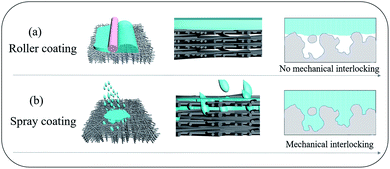 | ||
| Fig. 1 Schematic diagrams of (a) roller coating, and (b) spray coating to produce thin film polymer composites from incompatible polymers. | ||
We report here a highly efficient and simple technique to overcome PVA–PTFE incompatibility. By spray-coating aqueous PVA solutions on to commercial PTFE nanofibrous porous supports produced from biaxial stretching, the atomized PVA/water droplets could penetrate into the surface pores and fill the gaps between sub-layer fibres of the PTFE supports (Fig. 1). A strong mechanical interlocking structure was formed at the interface between PTFE fibers and the PVA coating layer. This was key to resolving the delamination problem of PVA layers from PTFE supports in these thin film composites. The lack of a gutter layer between the hydrophilic selective layer and hydrophobic porous support minimized resistance to water transport, imparting excellent desalination performances to our PVA/PTFE thin film composites in various modes – pervaporation (PV) and direct contact membrane distillation (DCMD). Even in the presence of organic foulants, the deployment of our PVA/PTFE composites in PV and DCMD modes outperformed state-of-the-art and commercial desalination membranes, respectively.
Experimental
Materials
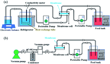
PTFE microfiltration membranes (average pore size – 317.6 nm) were purchased from the Beijing Shenghe Integrity Membrane Science and Technology Development Center (China). PVDF (purity ≥ 99.5%) was purchased from Sigma Aldrich, while polyvinylpyrrolidone (PVP K-30, purity ≥ 95.0%) was obtained from Gobekie Co., Ltd. LiCl (purity ≥ 95%) and NMP (purity ≥ 99.0%) was purchased from the Tianjin Fuchen Chemical Reagent Factory (China). Poly(vinyl alcohol) (PVA124, hydrolysis degree: 99.4%), sodium chloride (NaCl, purity ≥ 99.5%), and Tween 20 were acquired from Sinopharm Chemical Reagent Co., Ltd (China). An aqueous solution comprising 50 wt% 4-sulfophthalic acid (SPTA) was obtained from Tokyo Chemical Industry Co., Ltd and deionised water was obtained from a Millipore ultrapure water system.Membrane fabrication
| Membrane type | Technique | PVA thickness | No. of coats |
|---|---|---|---|
| PVA/PVDF/PTFE | NIPS | 2.4 μm | N.A. |
| RC-PVA/PTFE | Roller coating | 3.2 μm | 1 |
| SC-1-PVA/PTFE | Spray coating | 1.0 μm | 1 |
| SC-2.6-PVA/PTFE | 2.6 μm | 2 | |
| SC-3.5-PVA/PTFE | 3.5 μm | 3 | |
| SC-5.2-PVA/PTFE | 5.2 μm | 4 |
Membrane characterisation
 | (1) |
 | (2) |
 | (3) |
Results and discussion
Polymer compatibility
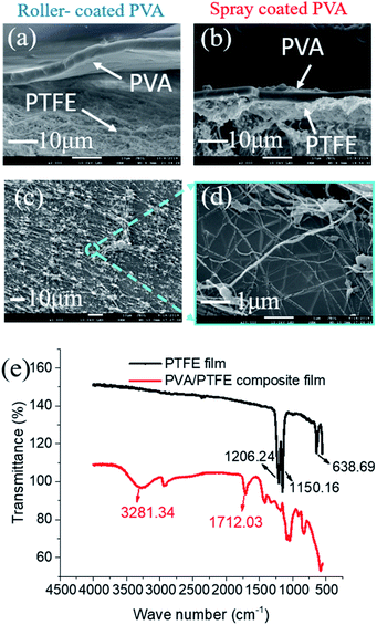
The low surface energy of PTFE resulted in its incompatibility with other materials.27–30 This was also evident here as roller-coated PVA layers delaminated from the PTFE fibrous supports (Fig. 3a). Since the PVA solution could not wet and permeate into the inter-fibre pores of the PTFE support, the poor physical attractions between the PVA layer and the PTFE support were too weak to enable firm adhesion of PVA layers. Meanwhile, spray-coated PVA layers adhered to the support layer, forming a tightly bound interlayer structure (Fig. 3b). The difference in structural stability was attributed to the ability to infiltrate inter-PTFE fiber pores by sub-micron sized PVA droplets. From Fig. S4,† we observed that PVA droplets first wrapped around PTFE fibers after one second of spray coating, and then formed firmly affixed 350 nm wide PVA islands on the PTFE fibers after 3 seconds. To explain the observation, we measured the surface tension of the PVA solutions (Fig. S3†), which decreased with the increment in PVA concentration. We also monitored a very fast evaporation process of atomized PVA droplets sprayed on a glass board (video in the ESI†). We hypothesize that the rapid decrements in the surface energy and sizes of the PVA droplets enable them to wet and flow into the pores of the PTFE substrate. After the droplets dried, the PTFE fibers were covered with a thin PVA film and their surfaces became hydrophilic. As more PVA was deposited on to the PVA islands, a dense PVA layer was formed. The improved compatibility between PVA and PTFE was evidenced by a significant amount of PTFE fibers within the PVA matrix, indicating good adhesion (Fig. 3c and d). The presence of PVA spray coated on to the PTFE fibrous support was validated with FTIR analyses (Fig. 3e). The structure (surface and cross-sectional morphology, and thickness of PVA) of the SC-PVA/PTFE composite membranes with different amounts of PVA is shown in Fig. S5 and Table S1.†Polymer adhesion
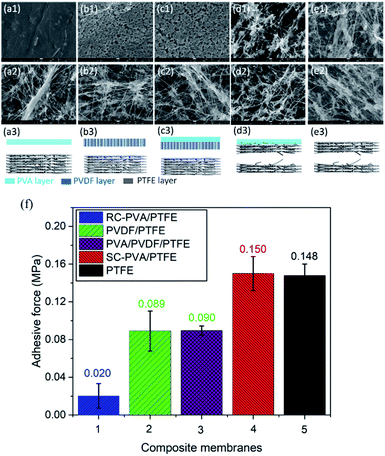
As shown in Fig. 4f, the adhesive strength between roller coated PVA layers and PTFE fibrous supports was 0.02 MPa. This was the lowest amongst all the samples studied here and is typical of delaminated layer structures (Fig. 4a1–a3).20,31–33 The low surface energy of PTFE and the absence of the mechanical interlocking structure between PVA and PTFE resulted in the low adhesive strength between these two topologically different layers.34 The adhesive strengths of PVDF/PTFE and PVA/PVDF/PTFE composites were similar and 4.5 fold higher than that of PVA/PTFE. Even with an intermediate PVDF layer, delamination remained prevalent, but at the PVDF–PTFE interface (Fig. 4b and c). Clearly, roller coating is not effective for overcoming the drastic differences in the surface energy between PTFE and other polymers studied here. Similar to PVA, PVDF did not infiltrate inter-PTFE fiber pores. Spray coated PVA/PTFE composites demonstrated the highest adhesive strength of 0.15 MPa, which was equivalent to the tearing strength of pristine PTFE fibrous supports as tearing occurred within the PTFE structure (Fig. 4d and e). Clearly, the significantly improved polymer adhesion benefits from the mechanical interlocking structure caused by spray coating.Desalination properties
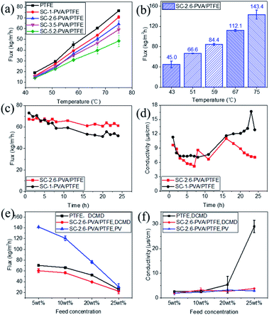
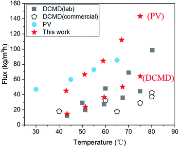
Desalination properties were assessed using an aqueous solution comprising 3.5 wt% NaCl as feed. All the composite membranes were first tested in DCMD mode and their desalination properties were compared with those of the pristine PTFE membrane. The PVA layers of roller coated composites (RC-PVA/PTFE) were partially delaminated from the PTFE substrate just after 1 h of desalination (Fig. S6†), indicating poor structural integrity and weak adhesion forces between PVA and PTFE. Therefore, desalination performances of RC-PVA/PTFE composites were not assessed. Desalination properties of other membranes were further determined in PV mode except for the PTFE and SC-1-PVA/PTFE composites. This was ascribed to the penetration of the feed solution into the pores of the PTFE support or surface defects of SC-1-PVA/PTFE composites under vacuum.The water fluxes of these membranes in DCMD modes at feed temperatures of 43.4 ± 0.3 to 75.0 ± 0.9 °C monotonically decreased with thicker PVA layers (Fig. 5a), corresponding to increased water transport resistance in thicker selective layers.35–39 The presence of an intermediate PVDF layer in roller coated PVA/PVDF/PTFE composites also impacted on water transport, reducing water flux by 42%, from 143.4 ± 8.9 kg m−2 h−1 to 83.4 ± 6.5 kg m−2 h−1 (reported in our previous study23). Amongst spray-coated defect-free PVA/PTFE thin film composites, SC-2.6-PVA/PTFE membranes demonstrated the highest water flux of 112.1 kg m−2 h−1 at a feed temperature of 67 °C (Fig. 5b) in PV mode, surpassing the state-of-the-art MXene/PAN composite membrane (85.4 kg m−2 h−1, 65 °C (ref. 40)) and PVA/PVDF/PTFE composite membrane (83.4 kg m−2 h−1, 70 °C (ref. 23)). The significantly higher water flux of the SC-2.6-PVA/PTFE membrane was attributed to the lower resistance of the PTFE substrate than the PVDF/PTFE support.
The presence of defect-free hydrophilic PVA dense selective layers enhanced PTFE resistance towards organic fouling. Tween 20, a widely applied non-ionic surfactant,41–44 was added to the 3.5 wt% NaCl feed solution to evaluate the anti-fouling properties of spray-coated PVA/PTFE membranes in DCMD mode. Our previous study showed that pores of the hydrophobic PTFE membrane were wetted by the feed solution within 8 h i.e. fouling resistance lasted only for 8 hours.23 In contrast, as shown in Fig. 5c and d, the conductivities of permeate solutions from spray coated PVA/PTFE composites remained stable at 10–15 μs cm−1, even after 16 hours of characterisation, demonstrating that the PTFE substrates were not wetted by the feed solution. The water flux of the SC-1-PVA/PTFE membrane decreased from 73 to 51.9 kg m−2 h−1 over 24 h, while the permeate solution conductivity increased after 16 h. The deteriorating desalination properties were due to the pinhole defects on the PVA layer (Fig. S5a†). At the beginning of the experiment, the pinholes in the PVA layer led to higher water fluxes than the defect-free SC-2.6-PVA/PTFE membrane. However, NaCl and Tween 20 were transported with liquid water through the pinholes. As water was vaporized, NaCl crystallised and Tween 20 accumulated at the surface of the PTFE porous substrate. As a result, the salt scale and organic fouling blocked the pores of the PTFE substrate, causing water flux of the SC-1-PVA/PTFE membrane to decrease over time. Without these defects, the water flux of SC-2.6-PVA/PTFE membranes remained stable at 64.6 ± 2.6 kg m−2 h−1 over 24 h, demonstrating a better resistance against organic fouling.
Other than desalinating water/salt mixtures that are identical to seawater, we also characterised the desalination performances of the PTFE and SC-2.6-PVA/PTFE membranes using concentrated brine solutions where the NaCl content was between 5 and 25 wt%. As salt concentrations increased from 5 to 25 wt%, the water fluxes of the PTFE membrane decreased from 70.3 ± 0.6 to 25.9 ± 0.5 kg m−2 h−1 in DCMD mode; while those of the SC-2.6-PVA/PTFE membrane reduced from 60.5 ± 3.7 to 22.4 ± 4.3 kg m−2 h−1 in DCMD mode and 141.7 ± 0.1 to 30.5 ± 5.9 kg m−2 h−1 in PV mode (Fig. 5e). The conductivity of the PTFE membrane permeate side solution increased with a higher salt content (Fig. 5f). This was due to the formation of salt crystals on the PTFE membrane surface i.e. ionic fouling, which hydrophilized the membrane surface, leading to partial wetting of the PTFE pores.45 Meanwhile in SC-2.6-PVA/PTFE composite membranes, the dense PVA layer prevented contact between salt crystals and the surface of PTFE fibrous supports. Therefore, the PTFE layer was able to maintain hydrophobicity and a high salt rejection rate. However, the water fluxes of SC-2.6-PVA/PTFE composite membranes decreased faster with a higher salt content in PV mode, possibly due to severe concentration polarisation effects on the feed side.46
Despite these impediments, SC-2.6-PVA/PTFE composite membranes continue to demonstrate high-water fluxes of 120.6 ± 4.2 kg m−2 h−1 in PV mode and 56.6 kg m−2 h−1 in DCMD mode for 10 wt% NaCl aqueous solution, highlighting the potential of such composites for recovering a concentrated brine solution. Meanwhile, the water fluxes of our membranes in DCMD mode were higher than those of commercially available DCMD membranes and on par with the best DCMD membranes prepared in labs23,40,47,48 (Fig. 6). Clearly, regardless of desalination modes, the ability to overcome the incompatibility between PVA and PTFE via spray coating is key for salt/water separation performance that surpasses those of commercial and state-of-the-art membranes.
Conclusions
We demonstrated that the incompatibility between a hydrophilic polymer, PVA, and a hydrophobic PTFE porous support can be overcome with a simple and robust technique, spray coating. The strong adhesion between spray coated PVA and PTFE supports avoided the need to use an intermediate polymer layer to overcome the significant difference in the surface energy between these incompatible materials. As a result, the water flux of the spray coated PVA/PTFE membrane in DCMD mode reached 64.2 ± 2.9 kg m−2 h−1 with a high salt rejection over 99.9% at a feed temperature of 75.0 ± 0.9 °C. This separation performance is competitive with that of the best commercial DCMD membranes. In addition, spray coated composite membranes were more resistant to both organic and ionic fouling during long-term desalination experiments. In PV mode, the PVA/PTFE composite membranes demonstrated a water flux of 143.4 ± 8.9 kg m−2 h−1 at 75 °C, outperforming existing PV desalination membranes. The excellent desalination performance of spray coated PVA/PTFE composites was upheld even with brine solutions. In summary, we have demonstrated a facile method to fabricate high performance polymer composites that may transform the way desalination is achieved.Conflicts of interest
There are no conflicts of interest to declare.Acknowledgements
This research was funded by the National Natural Science Foundation of China (51773011). CHL acknowledges the financial support from the Chancellor's Fellowship of The University of Edinburgh.References
- D. S. Sholl and R. P. Lively, Nature, 2016, 532, 435–437 CrossRef PubMed.
- E. Jones, M. Qadir, M. T. H. Van Vliet, V. Smakhtin, V. Smakhtin and S.-M. Kang, Sci. Total Environ., 2019, 657, 1343–1356 CrossRef CAS PubMed.
- K. Scott, Handbook of Industrial Membranes, 2nd edn, 1998 Search PubMed.
- J. Mansouri, S. Harrisson and V. Chen, J. Mater. Chem., 2010, 20, 4567 RSC.
- E. Guillen-Burrieza, A. Ruiz-Aguirre, G. Zaragoza and H. A. Arafat, J. Membr. Sci., 2014, 468, 360–372 CrossRef CAS.
- J. L. Xu, N. M. Srivatsa Bettahalli, S. Chisca, M. K. Khalid, N. Ghaffour, R. Vilagines and S. P. Nunes, Desalination, 2018, 432, 32–39 CrossRef CAS.
- P. Peng, A. G. Fane and X. D. Li, Desalination, 2005, 173, 45–54 CrossRef CAS.
- P.-J. Lin, M.-C. Yang, Y.-L. Li and J.-H. Chen, J. Membr. Sci., 2015, 475, 511–520 CrossRef CAS.
- L. Madauss, J. Schumacher, M. Ghosh, O. Ochedowski, J. Meyer, H. Lebius, B. Ban-d'Etat, M. E. Toimil-Molares, C. Trautmann, R. G. H. Lammertink, M. Ulbricht and M. Schleberger, Nanoscale, 2017, 9, 10487–10493 RSC.
- H. Chen, L. Bednarova, R. Besser and W. Lee, Appl. Catal., A, 2005, 286, 186–195 CrossRef CAS.
- A. Simaite, B. Tondu, P. Soueres and C. Bergaud, ACS Appl. Mater. Interfaces, 2015, 7, 19966–19977 CrossRef CAS PubMed.
- A. Baldan, J. Mater. Sci., 2004, 39, 1–49 CrossRef CAS.
- L. Chen, Z. D. Gu, L. Li, W. W. Lei, Q. F. Rong, C. Q. Zhao, Q. S. Wu, Z. Gu, X. Jin, L. Jiang and M. Liu, J. Mater. Chem. A, 2018, 6, 15147–15153 RSC.
- J. Q. Wang, C. C. Li, F. Wang, B. Yu, Y. Y. Luo, H. Z. Zeng and H. L. Zhu, Prog. Org. Coat., 2019, 135, 565–573 CrossRef CAS.
- H. M. Song, H. W. Yu, L. J. Zhu, L. X. Xue, D. C. Wu and H. Chen, React. Funct. Polym., 2017, 114, 110–117 CrossRef CAS.
- A. G. Lin, S. Shao, H. Z. Li, D. Y. Yang and Y. Kong, J. Membr. Sci., 2011, 371, 286–292 CrossRef CAS.
- E. Adem, M. Avalos-Borja, E. Bucio, G. Burillo, F. F. Castillon and L. Cota, Nucl. Instrum. Methods Phys. Res., Sect. B, 2005, 234, 471–476 CrossRef CAS.
- C.-Y. Tu, Y.-C. Wang, C.-L. Li, K.-R. Lee, J. Huang and J.-Y. Lai, Eur. Polym. J., 2005, 41, 2343–2353 CrossRef CAS.
- X. Wang, Y. X. Tian, Z. B. Wang and Y. Tao, J. Macromol. Sci., Part B: Phys., 2010, 50, 172–178 CrossRef.
- Q.-C. Xia, M.-L. Liu, X.-L. Cao, Y. Wang, W. H. Xing and S.-P. Sun, J. Membr. Sci., 2018, 562, 85–111 CrossRef CAS.
- D. Bhandari, K. O. Olanrewaju, N. Bessho, V. Breedveld and W. J. Koros, Sep. Purif. Technol., 2013, 104, 68–80 CrossRef CAS.
- D. J. Gardner, M. Blumentritt, L. Wang and N. Yildirim, Rev. Adhes. Adhes., 2014, 2, 127–172 CrossRef CAS.
- J. Q. Meng, P. Li and B. Cao, ACS Appl. Mater. Interfaces, 2019, 11, 28461–28468 CrossRef CAS PubMed.
- B. Liang, Q. Li, B. Cao and P. Li, Desalination, 2018, 433, 132–140 CrossRef CAS.
- Y. L. Xue, C. H. Lau, B. Cao and P. Li, J. Membr. Sci., 2019, 575, 135–146 CrossRef CAS.
- Y. L. Xue, J. Huang, C. H. Lau, B. Cao and P. Li, Nat. Commun., 2020, 11, 1461 CrossRef CAS PubMed.
- R. Takata, T. Iwao and M. Yumoto, Electronics and Communications in Japan, 2016, 99, 93–99 CrossRef.
- S. S. Feng, Z. X. Zhong, Y. Wang, W. H. Xing and E. Drioli, J. Membr. Sci., 2018, 549, 332–349 CrossRef CAS.
- S. K. Xue, C. C. Li, J. M. Li, H. L. Zhu and Y. H. Guo, J. Membr. Sci., 2017, 524, 409–418 CrossRef CAS.
- F. Wang, H. L. Zhu, H. P. Zhang, H. Y. Tang, J. Y. Chen and Y. H. Guo, Journal of Water Process Engineering, 2015, 8, 11–18 CrossRef.
- L. Setiawan, L. Shi, W. B. Krantz and R. Wang, J. Membr. Sci., 2012, 423–424, 73–84 CrossRef CAS.
- X.-M. Li, Y. Ji, Y. Yin, Y.-Y. Zhang, Y. Wang and T. He, J. Membr. Sci., 2010, 352, 173–179 CrossRef CAS.
- D. F. Li, T.-S. Chung and R. Wang, J. Membr. Sci., 2004, 243, 155–175 CrossRef CAS.
- X. Deng, F. Schellenberger, P. Papadopoulos, D. Vollmer and H.-J. Butt, Langmuir, 2013, 29, 7847–7856 CrossRef CAS PubMed.
- L. Li, J. W. Hou, Y. Ye, J. Mansouri and V. Chen, Desalination, 2017, 422, 49–58 CrossRef CAS.
- Z. L. Xie, M. Hoang, T. Duong, D. Ng, B. Dao and S. Gray, J. Membr. Sci., 2011, 383, 96–103 CrossRef CAS.
- I. Prihatiningtyas, A. Volodin and B. Van der Bruggen, Ind. Eng. Chem. Res., 2019, 58, 14340–14349 CrossRef CAS.
- C. Zhou, J. J. Zhou and A. S. Huang, Microporous Mesoporous Mater., 2016, 234, 377–383 CrossRef CAS.
- R. Zhang, B. Liang, T. Qu, B. Cao and P. Li, Environ. Technol., 2019, 40, 312–320 CrossRef CAS PubMed.
- G. Z. Liu, J. Shen, Q. Liu, G. P. Liu, J. Xiong, J. Yang and W. Q. Jin, J. Membr. Sci., 2018, 548, 548–558 CrossRef CAS.
- A. Trentin, C. Güell, T. Gelaw, S. de Lamo and M. Ferrando, Sep. Purif. Technol., 2012, 88, 70–78 CrossRef CAS.
- H. J. Tanudjaja and J. W. Chew, J. Membr. Sci., 2018, 560, 21–29 CrossRef CAS.
- H. Rabiee, S. M. S. Shahabadi, A. Mokhtare, H. Rabiei and N. Alvandifar, J. Environ. Chem. Eng., 2016, 4, 4050–4061 CrossRef CAS.
- L. Han, Y. Z. Tan, C. Xu, T. Xiao, T. A. Trinh and J. W. Chew, J. Membr. Sci., 2019, 588, 117196 CrossRef CAS.
- M. Rezaei, D. M. Warsinger, V. J. Lienhard, M. C. Duke, T. Matsuura and W. M. Samhaber, Water Res., 2018, 139, 329–352 CrossRef CAS PubMed.
- Q. Z. Wang, N. Li, B. Bolto, M. Hoang and Z. Xie, Desalination, 2016, 387, 46–60 CrossRef CAS.
- P. Wang, M. M. Teoh and T.-S. Chung, Water Res., 2011, 45, 5489–5500 CrossRef CAS PubMed.
- M. M. A. Shirazi, A. Kargari and M. Tabatabaei, Chem. Eng. Process., 2014, 76, 16–25 CrossRef CAS.
Footnote |
| † Electronic supplementary information (ESI) available. See DOI: 10.1039/d0ta00871k |
| This journal is © The Royal Society of Chemistry 2020 |

