Experimental performance investigation of a 2 kW methanation reactor
Received
17th February 2018
, Accepted 13th March 2018
First published on 14th March 2018
Abstract
A 2 kW methanation reactor was designed, built and tested for the gas phase hydrogenation of CO2 to CH4. The reactor is a single-stage, fixed-bed reactor. A commercial catalyst with 0.5% wt Ru on an alumina support was applied and characterized using TEM imaging. A thermal model of the process was developed in order to effectively design the cooling system and estimate the temperature gradients within the reactor. The conversion efficiency was investigated experimentally using transmission infrared spectroscopy. The reactor temperature set point was varied from 140 °C to 400 °C, the space velocity ranged from 0.14 s−1 to 0.55 s−1 (corresponding to 0.40–1.55 ml g−1 s−1) and the pressure was set to 5 bar. A maximal conversion of 99% was measured at a temperature of 260 °C and a space velocity of 0.14 s−1. A CO2 conversion of 97% was reached at a target flow rate of 50 g h−1 H2 and a temperature set point of 280 °C. Such conversions are very high for a single-stage reactor and are partly due to the inhomogeneous temperature distribution within the catalyst bed, which allowed the balancing of the kinetic and thermodynamic effects. The reactor presented in this paper is installed as a part of the small-scale demonstrator of renewable energy to synthetic hydrocarbon conversion of EPFL Valais/Wallis.
Introduction
Since the beginning of industrialization, our economy has been based on fossil fuels, first using coal in tenders, and then moving to oil at the end of the 19th century with the advent of combustion engines and automobiles. However, the combined trends of limited fossil fuel reserves, increasing energy consumption and rising concerns about climate change induced a change in the energy landscape, with a shift from fossil fuels to renewable, sustainable energy sources such as wind and solar.1–3 However, these new energy sources are difficult to control and predict. Thus, the development of large-scale energy storage systems is a crucial issue. None of the existing energy storage technologies such as batteries, pumped hydroelectric storage or fly wheels can compete with the energy density of hydrocarbons.4 Therefore, a significant amount of effort is being directed into research for the production of synthetic fuels.5–8 The development of the methanation reactor presented in this article took place as a part of the construction of a small-scale demonstration plant for the conversion of solar energy to synthetic hydrocarbons. The layout of the complete demonstrator is shown in Fig. 1 and described in detail in ref. 9. The demonstrator pilot plant consists of solar cells, batteries for electricity storage, a PEM electrolyser, a metal hydride hydrogen storage system, a metal hydride compressor, a CO2 absorber and chemical reactors. The installation is designed such as to provide for the global average consumption of a single person, which amounts to 2000 W.10 This includes all primary energy sources, i.e. coal, oil, gas, and electricity, among others. Thus, the total average energy consumption of a single person is around 48 kW h per day. The energy is handled in four sectors: (1) solar energy converted to electricity in photovoltaic cells, (2) electricity stored in batteries, (3) hydrogen produced by electrolysis, and (4) methane and methanol formed from hydrogen and carbon dioxide. The goal of this project is to demonstrate the technical feasibility of synthetic fuel production from renewable energies in a closed carbon cycle.
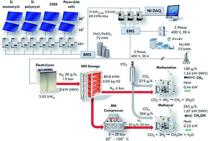 |
| | Fig. 1 Layout of the Small-Scale Demonstrator (SSDS) plant for the conversion of solar energy to synthetic hydrocarbons (from ref. 5). This installation displays the full conversion of solar energy to synthetic hydrocarbons via photovoltaic electricity generation, electricity storage in batteries, water electrolysis to produce hydrogen, metal hydride hydrogen storage and, finally, CO2 reduction to synthetic hydrocarbons. The present paper describes in detail the performance of the methanation reactor which is part of this installation. | |
The size of the installation allows the testing of emerging technologies on an intermediate scale between the laboratory environment and a full-scale industrial installation. The methanation reactor is one of the core components of this project. It is positioned at the end of the installation, converting carbon dioxide and the renewably produced hydrogen into methane. The reactor is designed to convert 50 g h−1 of hydrogen, which corresponds to a production of 100 g h−1 of methane. The equivalent power based on the Higher Heating Value (HHV) amounts to 1.54 kW. This article presents the design, construction and performance characterization of the methanation reactor.
Fixed-bed reactor design
The fixed-bed reactor was designed based on the catalyst, thermodynamic and kinetic modeling and thermal management. This section presents the different steps for the design of the reactor.
Catalyst
Three main types of catalysts exhibit high activity and selectivity for the Sabatier reaction: nickel, cobalt and ruthenium based catalysts.11–13 Nickel based catalysts are the most widely used. Garbarino et al. studied several Ni-based catalysts over Al2O3 supports at atmospheric pressure with a constant space velocity of 15 s−1. They noticed that the highest CO2 conversion and the highest methane yields were reached at 500 °C for all the Ni-based samples that were investigated.14 Several supports (Y2O3, Sm2O3, ZrO2, CeO2, Al2O3, and La2O3) with 10% wt Ni loading were also tested by Muroyama et al. at atmospheric pressure with the space velocity varying from 28 s−1 to 44 s−1. The maximal CO2 conversion (75–80%) was reached with the Y2O3 support and Sm2O3 support at 250 °C.15 Song et al. also performed different experiments with a 10% wt Ni-based catalyst under a pressure of 15 bar with a space velocity of 3 s−1. Their results demonstrate much lower CO2 conversion of only 6.9% despite a high methane selectivity of 88.9% with Al2O3 supports at 380 °C. However, changing the support to La2O3 allowed them to reach 100% CO2 conversion under the same conditions.16 Borgschulte et al. used Ni deposited on zeolites in order to selectively remove the water byproduct from the reaction zone and found full conversion of CO2 to methane at temperatures as low as 170 °C.17 Cobalt based catalysts have also been investigated for the Sabatier process. Zhou et al. reached 50% CO2 conversion for Co-based catalysts at atmospheric pressure at 300 °C with a space velocity of 6.1 ml g−1 s−1.18 In 2014, Mirzaei et al. reached 75% CO2 conversion for a 10% wt Co-based catalyst over a MgO support at atmospheric pressure at 700 °C with a space velocity of 3.3 ml g−1 s−1.19 The units of space velocity herein refer to the feed gas flow (ml s−1) per mass of catalyst in the reactor. The last and perhaps most interesting category of catalysts for the Sabatier reaction is ruthenium based catalysts. As early as 1973, Lunde and Kester conducted a study on the Sabatier reaction using 0.5% wt Ru on an Al2O3 support as the catalyst. They carried out experiments in a 4.15 cm3 reactor between 200 °C and 360 °C with the space velocity ranging from 0.8 to 2.2 s−1. They reported a maximal CO2 conversion of 85%.20,21 More recently, Schoder et al. investigated Ru/Al2O3 catalysts. They reached a CO2 conversion of 89% with a methane selectivity close to 100% at a temperature of 300 °C, ambient pressure and a space velocity of 1.7 s−1.22 Garbarino et al. compared a Ni-based catalyst (20% wt Ni/Al2O3) with a Ru-based catalyst (3% wt Ru/Al2O3) at atmospheric pressure and a space velocity of 4.2 s−1. The Ru-based catalyst showed better results. Indeed, a CO2 conversion of over 90% was reached at 380 °C while the maximum methane yield with the Ni-based catalyst reached only 80% at 400 °C.23,24 While Ru-based catalysts are more expensive than Ni-based catalysts, the actual cost of the catalysts is small as compared to the cost of the overall setup – even on an industrial scale. Therefore, and in order to reach a high conversion, Ru-based catalysts are preferable.
Catalyst characterization
Based on the reported results, a commercial ruthenium based catalyst was selected for the chemical reactor. The catalyst was supplied by Sigma Aldrich and has 0.5% wt ruthenium loading on alumina. It is pressed into cylindrical pellets with an average diameter of 3.2 mm and a length of 5 mm. The reactor bed is filled with 250 g of this catalyst. Transmission electron microscopy (TEM, FEI, Tecnai G2 Spirit Twin) analysis was conducted in order to determine the particle size of ruthenium. Both new and used catalysts were measured, with no significant change in the structure and particle size. The sample was prepared by mixing 0.01 g of sample in 1 ml of ethanol by sonication for 30 min and dispersing in a carbon grid. The typical ruthenium particle size is in the range of 9–17 nm and the average size is 11.5 nm, as shown in Fig. 2. This is slightly larger than that reported by Kwak et al., who examined STEM images of a similar catalyst (0.1% wt Ru on Al2O3) and found ruthenium particle sizes of up to 5 nm once the catalyst had been used.25 The average ruthenium particle size of 11.5 nm corresponds to a specific surface area of 22.4 m2 g−1 when considering spherical particles.
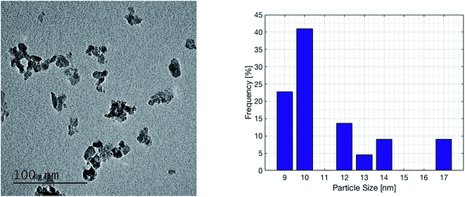 |
| | Fig. 2 Transmission electron microscopy (TEM) imaging and (left) size distribution of the ruthenium particles on the commercial catalyst with 0.5% wt Ru deposited on Al2O3. The ruthenium particle size ranges from 9 nm to 17 nm. | |
Thermodynamic and kinetic modelling
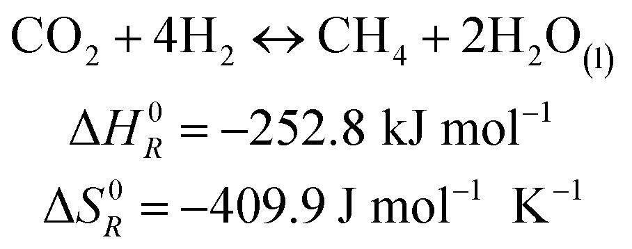
The methanation reaction was first discovered by the French chemist Paul Sabatier at the beginning of the 20th century.26 The reaction describes the production of methane and water from hydrogen and carbon dioxide, as shown in eqn (1). This process is highly exothermic, with a reaction enthalpy of −252.8 kJ mol−1 under standard conditions (T = 273.15 K, p = 1.013 × 10⁵ Pa).| |  | (1) |
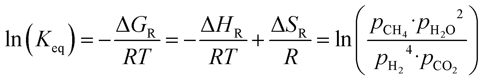
The equilibrium conversion of the Sabatier reaction can be modeled with standard thermodynamic functions. First, the equilibrium constant is calculated using eqn (2). The enthalpy and entropy of reaction are computed as a function of the temperature using eqn (3) and (4), with the coefficients taken from ref. 27 and summarized in Table 1. The absolute pressure in the chemical reactor is maintained constant at p, and is described as the sum of all partial pressures, as postulated in eqn (5). Therefore, p is the total pressure of the system. It is assumed that the methanation reaction is the only chemical reaction happening and that the process occurs under stoichiometric conditions (eqn (6) and (7)). It is further assumed that all reactants and products are in the gas phase and follow ideal behavior.
| | 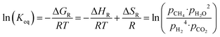 | (2) |
| | | S0x(T) = A·ln(T) + B·T + C·T2/2 + D·T3/3 − E/(2·T2) + G | (3) |
| | | H0x(T) − H0298 = A·T + B·T2/2 + C·T3/3 + D·T4/4 − E/T + F − H | (4) |
| | | p = pH2 + pCO2 + pCH4 + pH2O | (5) |
Table 1 Coefficients for the calculation of the enthalpy and entropy of reaction as a function of the temperature
| Coefficient |
CO2 |
H2 (298 < T < 1000 K) |
H2 (1000 < T < 2500 K) |
CH4 |
H2O (l) |
H2O (v) |
| A |
−0.7030 |
33.06 |
18.56 |
−0.70 |
−203.61 |
30.09 |
| B |
108.48 |
−11.36 |
12.26 |
108.48 |
1523.29 |
6.83 |
| C |
−42.52 |
11.43 |
−2.86 |
−42.52 |
−3196.41 |
6.79 |
| D |
5.86 |
−2.77 |
0.27 |
5.86 |
2474.46 |
−2.53 |
| E |
0.68 |
−0.16 |
1.98 |
0.68 |
3.86 |
0.08 |
| F |
−76.84 |
−9.98 |
−1.15 |
−76.84 |
−256.55 |
−250.88 |
| G |
158.72 |
172.71 |
156.29 |
158.71 |
−488.72 |
223.40 |
| H |
−74.87 |
0 |
0 |
−74.87 |
−285.83 |
−241.83 |
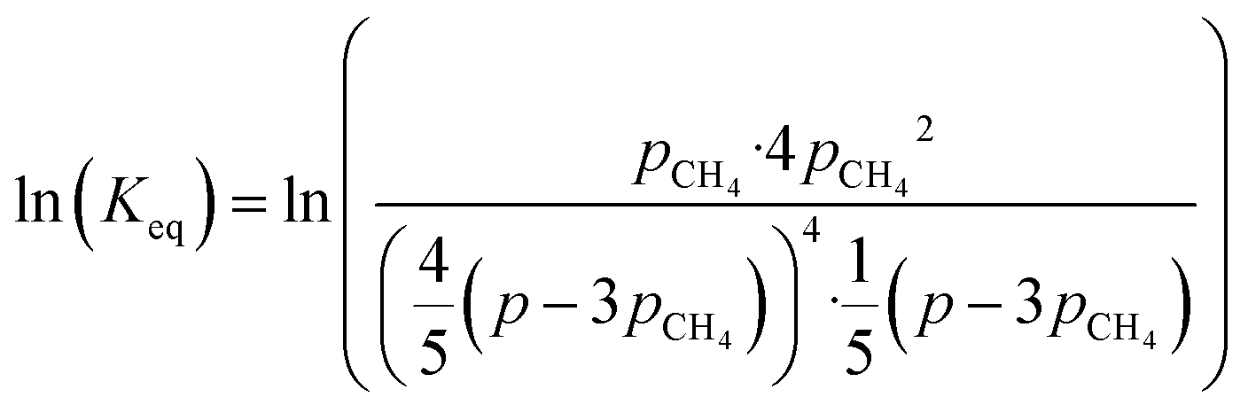
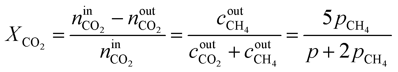
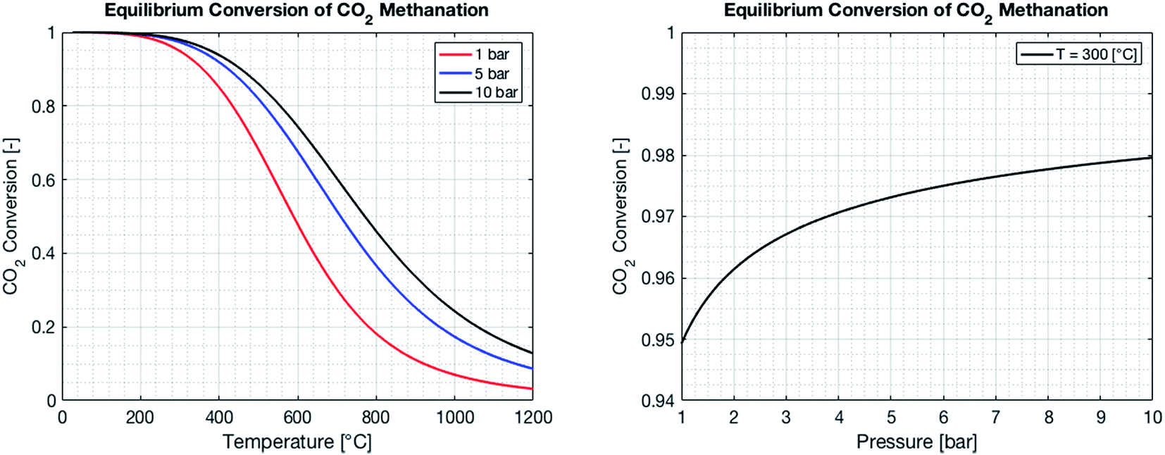
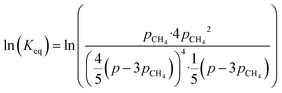
By combining eqn (2)–(7), it is possible to express the equilibrium constant as a function of a single variable such as the partial pressure of methane pCH4. The CO2 conversion can eventually be calculated by first solving eqn (8) numerically for the partial pressure of methane, and then plugging it into eqn (9). The right-hand side of eqn (9) was deduced from mass conservation. The equilibrium curves as a function of the temperature and as a function of the pressure are shown in Fig. 3.
| |  | (8) |
| |  | (9) |
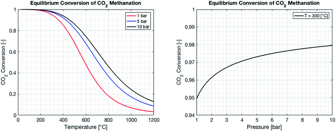 |
| | Fig. 3 Equilibrium CO2 conversion to methane for stoichiometric feeding as a function of the temperature (left) and the pressure. As the reaction is exothermic, the equilibrium is shifted to the reactants as the temperature increases (left). An increase in pressure results in an increase of the CO2 conversion, as the number of molecules is reduced during the reaction (right). | |
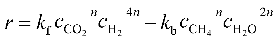
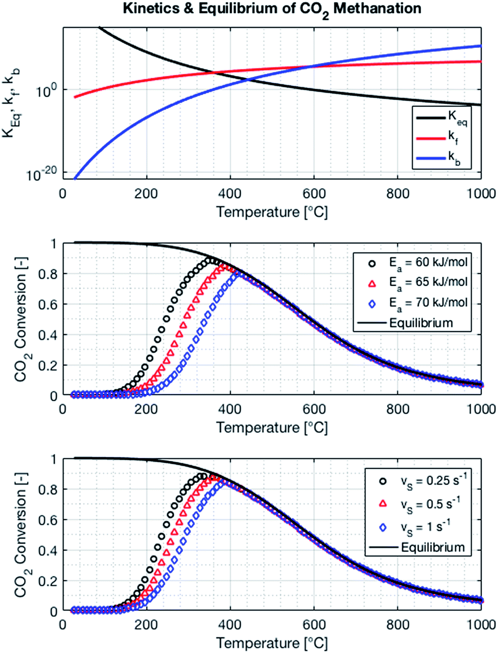
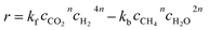
The kinetics of the methanation reaction can be modelled following Arrhenius' law shown in eqn (10), where kf is the forward reaction rate constant, k0 represents the pre-exponential factor and Ea stands for the activation energy. These parameters are typically determined experimentally. The backward reaction rate can be computed by combining eqn (2) and (10), resulting in eqn (11). The actual reaction rate is then the combination of the forward and backward reactions, as shown in eqn (12). Lunde and Kester found that n = 0.25 best fitted the results for the methanation reaction.21 The reason why this factor is significantly lower than 1 can be explained by the fact that the reaction does not occur in the gas phase, but on the catalyst surface. Thus, only the molecules present on a catalytically active site can react. In their work, Lunde and Kester also measured the activation energy Ea and the pre-exponential factor k0 to be 71 kJ mol−1 and 2.34 × 10⁹ per atm1/4 per hour, respectively. The temperature dependency of the equilibrium constant and the forward and backward reaction rate constants is shown in Fig. 4 alongside the CO2 conversion for different activation energies (Ea = 60, 65 and 70 kJ mol−1) and space velocities (vs = 0.25, 0.5 and 1 s−1, corresponding to 0.70, 1.41 and 2.82 ml g−1 s−1). The values for the concentration of the reactants and products in eqn (12) were set based on stoichiometry. The extent of reaction was initially set to zero at room temperature (i.e. the methane and water concentrations are set to zero), and then iteratively increased based on the calculated reaction rate. As expected, the CO2 conversion increases with decreasing activation energy and decreasing space velocity.
| |  | (10) |
| |  | (11) |
| |  | (12) |
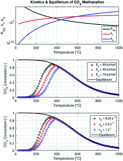 |
| | Fig. 4 Equilibrium and reaction rate constants (top) and influence of activation energy (middle) and the space velocity (bottom) on the kinetics of the methanation reaction. The pressure of the system is set to 1 bar, the space velocity to 0.5 s−1 (middle plot) and the activation energy to 65 kJ mol−1 (bottom plot). | |
Thermal management
The thermal management of the methanation reactor has to address two issues: first, the reactor has to be pre-heated in order to start the reaction. Second, and as already mentioned, the methanation reaction is highly exothermic. Therefore, an adequate thermal management system has to be developed in order to effectively remove the heat from the reaction zone and to control the temperature of the chemical reactor. A heating collar with a power of 540 W and a maximal allowable temperature of 400 °C is installed around the reactor tube in order to preheat the reaction zone at startup. Furthermore, the outer wall of the reactor tube is insulated such that the startup time is minimized.
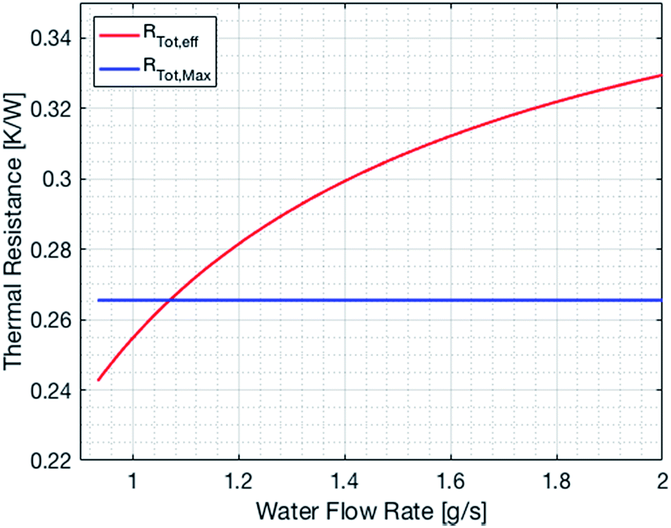
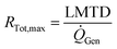
The cooling of the reactor during operation is ensured by six cooling tubes embedded directly in the catalyst bed. The total heat generated in the chemical reactor is calculated using eqn (13). Therefore, the value for the reaction enthalpy has to be calculated under the reaction conditions. It is assumed that the reaction occurs above 140 °C and that water exits the reactor in the vapor phase. Typically, the water condenses outside the reactor. Therefore, the value for the reaction enthalpy under operating conditions was calculated to be 152 kJ mol−1 and the total heating power of the reaction amounts to 264 W. The maximal allowable thermal resistance given the existing thermal gradient between the reactor and the cooling fluid can be computed using eqn (14), where LMTD stands for the logarithmic mean temperature difference. The effective thermal resistance RTot,eff is computed using eqn (17), where RConv,i stands for the inner convective resistance, RCond stands for the conductive resistance of the pipe and RConv,o represents the outer convective resistance. Dissipating such a high heat load by using air as the cooling medium would require a fluid velocity of over 100 m s−1 in the cooling tubes, which is not realistic. Therefore, water is chosen as the cooling medium. The flow rate of water enters the calculation as it determines the outlet temperature of the cooling fluid, as seen in eqn (15) and (16). The required water flow rate is extracted from Fig. 5. A minimal water flow rate of 1.1 g s−1 is required to fulfill the thermal requirements.
| | ![[Q with combining dot above]](https://www.rsc.org/images/entities/i_char_0051_0307.gif) Gen = ṅCH4ΔHR Gen = ṅCH4ΔHR | (13) |
| |  | (14) |
| |  | (15) |
| | | Gen = ṁH2Oc(Tw,out − Tw,in) | (16) |
| | | RTot,eff = RConv,i + RCond + RConv,o | (17) |
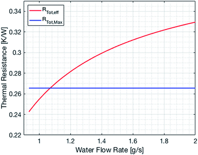 |
| | Fig. 5 Effective and maximal overall thermal resistance of the cooling system as a function of the water flow rate. | |
Reactor design and performance
Reactor design
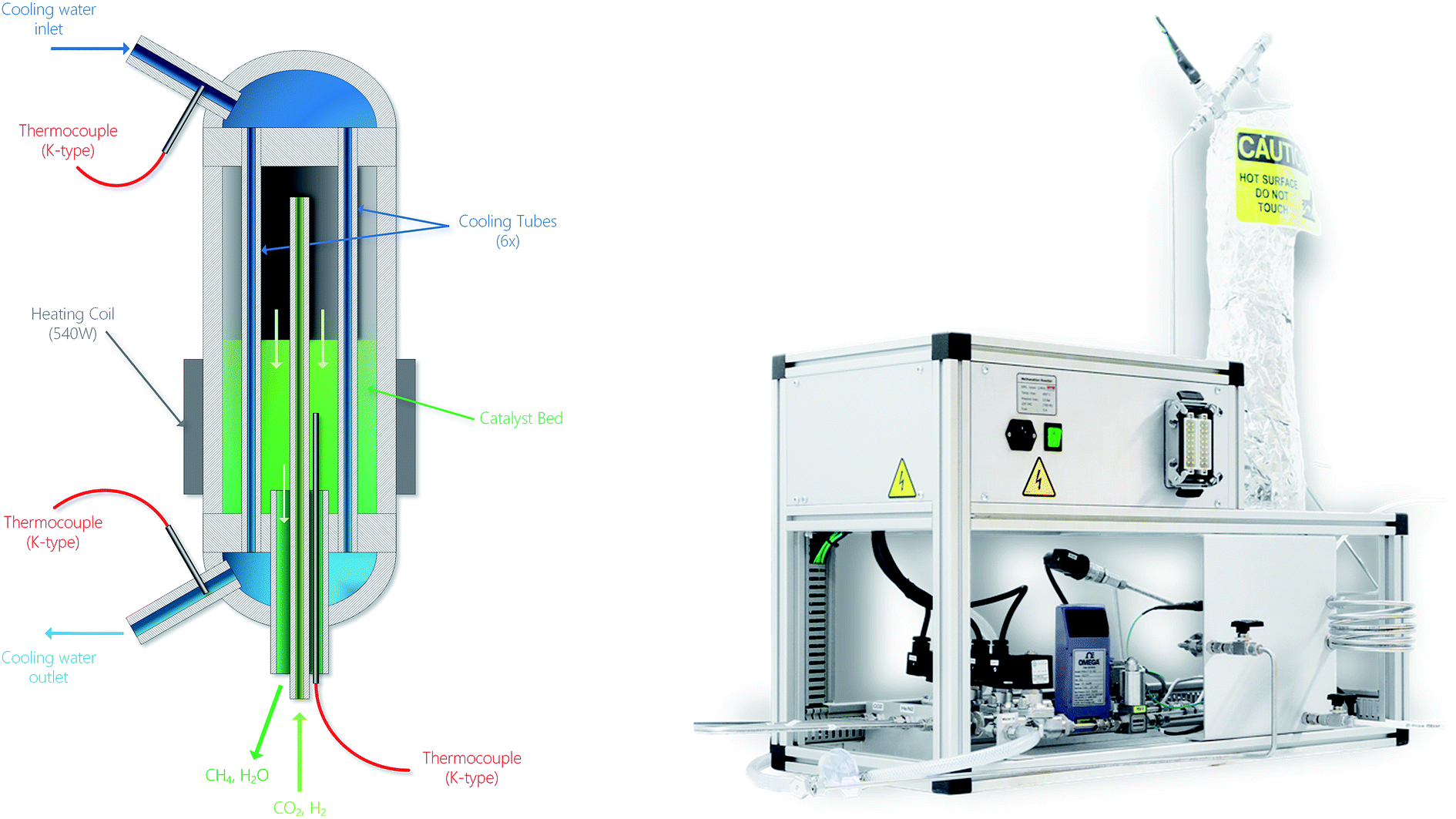
The layout of the experimental setup is represented graphically in Fig. 6. The gas stream of the reactants is controlled by two mass flow meters (Vögtlin Red-y Smart). A third gas line is built in for helium or nitrogen, which can be used to flush the system or for calibration purposes. The reactor was designed to operate at temperatures up to 400 °C and pressures up to 10 bar with a structural safety factor of 4. Pressure relief valves are installed on the main gas line and on the cooling loop to protect the system from overpressure. The flow rate of the cooling water is controlled by a proportional valve (Omega FSV 12). The exhaust stream of the reactor is cooled down in order to condense the water. The composition of the remaining gases is analyzed using a Fourier Transform Infrared Spectrometer (FT-IR, Alpha Bruker). Several pressure and temperature sensors are embedded in the system to accurately monitor the testing conditions. A picture of the reactor setup is shown in Fig. 7.
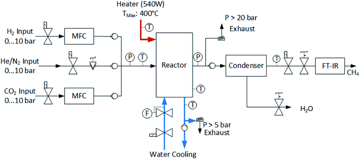 |
| | Fig. 6 Schematic of the experimental setup for the methanation reactor. The incoming flow of hydrogen and carbon dioxide is controlled using mass flow controllers. An electrical heating element is embedded in the chemical reactor in order to start off the reaction. In the steady state, the reactor is cooled with a liquid cooling system. The exhaust gases contain a mixture of methane and water vapor. The water is condensed and separated. The pressure in the reactor is controlled using a manual back-pressure valve located at the exit of the reactor. Finally, the products are analyzed in a Fourier-Transform Infrared Spectrometer (FT-IR). | |
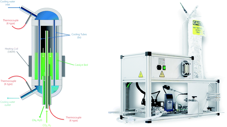 |
| | Fig. 7 Schematic of the methanation reactor (left) and picture of the overall experimental setup (right). Especially notice the location of the thermocouple situated in the catalyst bed of the chemical reactor in the left-hand side figure. In the right-hand side picture, the top-left box contains the electrical and electronic components. The bottom segment contains the gas handling system. The vertical part on the right is the actual chemical reactor. | |
The design of the methanation reactor is driven by thermodynamic, kinetic and thermal constraints as well as boundary conditions evolving from the overall design of the SSDS. In the present case, the target production is set to 100 gCH4 h−1. This value is derived from the design of the overall demonstrator plant shown in Fig. 1. The plug-flow reactor is fed with a stoichiometric mixture of H2 and CO2, with nominal volumetric flows of 9.33 Nl min−1 (50 g h−1) and 2.33 Nl min−1 (275 g h−1), respectively. The total power of the reactor amounts to around 2 kW, split into 1.54 kW contained in the produced methane and 0.44 kW supplied in the form of heat.
FT-IR calibration
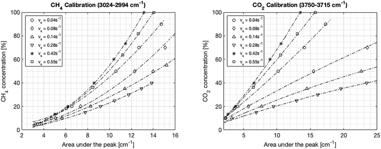
In the first step, the FT-IR is calibrated for both CO2 and CH4. The CO2 infrared spectrum exhibits three main peaks at wavelengths of around 650 cm−1, 2300 cm−1 and 3600 cm−1. However, the first two peaks become saturated at different CO2 concentrations of around 70% and 20%, respectively. Inversely, the peak located between 3750 and 3715 cm−1 increased linearly with the CO2 concentration up to a concentration of 100%. Therefore, this last peak was chosen for the calibration. The methane infrared spectrum has two specific peaks at 1300 cm−1 and 3000 cm−1. Unlike for CO2, none of these peaks become saturated. However, the peak at 3000 cm−1 is preferred in order to avoid a potential overlap with the water peak resulting from imperfect condensation. The integration boundaries are set to 3024–3002 cm−1. The calibration is performed at six different flow rates between 1.5 and 23.3 Nl min−1 corresponding to space velocities from 0.04 to 0.55 s−1 (0.11–1.55 ml g−1 s−1) in order to account for the change in pressure in the IR cell. The calibration curves are shown in Fig. 8. The root mean square error from the fits ranges from 0.3% to 2.1% and the regression coefficients are above 0.996 for all fits. The trend curves typically deviate slightly from the linear behavior predicted by Lambert–Beer's law, especially at low concentrations. Finally, a general correlation can be deduced for the concentration of CO2 and CH4 as a function of the IR spectral peak area and the space velocity, as shown in eqn (18) and (19), where vs is the space velocity and ACO2 and ACH4 are the areas under the infrared spectra.| | | CCO2 = 2.91 + 7.65·ACO2 − 84.26·vs − 0.051·ACO22 − 10.02·ACO2·vs + 172.70·vs2 | (18) |
| | | CCH4 = −12.17 + 4.27·ACH4 + 2.65·vs + 0.32·ACH42 − 14.54·ACH4·vs + 126.90·vs2 | (19) |
 |
| | Fig. 8 FT-IR calibration curves for CH4 (left) and CO2 (right) at different space velocities. The dependence of the signal on the pressure in the cell – thereby on the flow – is seen impressively. | |
Reactor performance
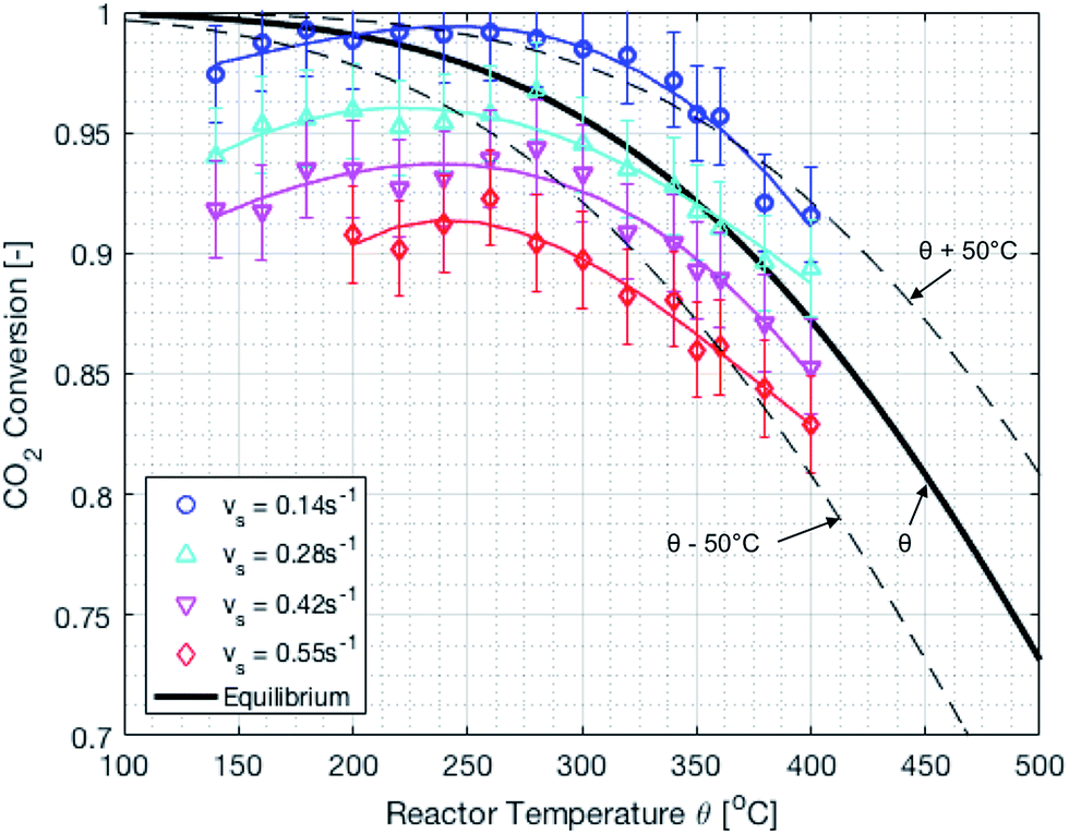
The reactor performance is tested under various conditions of temperature and space velocity. For all experiments, the pressure was set to 5 bar. This is justified by both thermodynamic reasons and external technical parameters. From Fig. 3, it is seen that an increase in pressure beyond 5 bar only leads to a marginal increase in the equilibrium conversion. Furthermore, and from the point of view of implementation, CO2 from atmospheric capture is available at low pressure. Thus, in order to avoid the use of an external compressor for CO2, the reactor pressure is limited to 5 bar. The values for the CO2 conversion are calculated using eqn (9). The experimental uncertainty is calculated following the Kline–McClintock method and the experimental error in the concentrations is taken as the RMSE from the calibration fits.28 The domain of investigation for the space velocity and the temperature was set to 0.14–0.55 s−1 and 140–400 °C. These boundaries were defined to match the SSDS boundary conditions (quantity of methane produced) and reactor limits (maximal temperature), as well as thermodynamic modelling and literature review. A total of 57 experiments were carried out in that domain. The calculated conversions are shown in Fig. 9.
 |
| | Fig. 9 Experimental CO2 conversion at different temperatures and space velocities. The dashed lines represent temperature variations of ±50 °C. There is an optimum temperature maximizing the CO2 conversion. | |
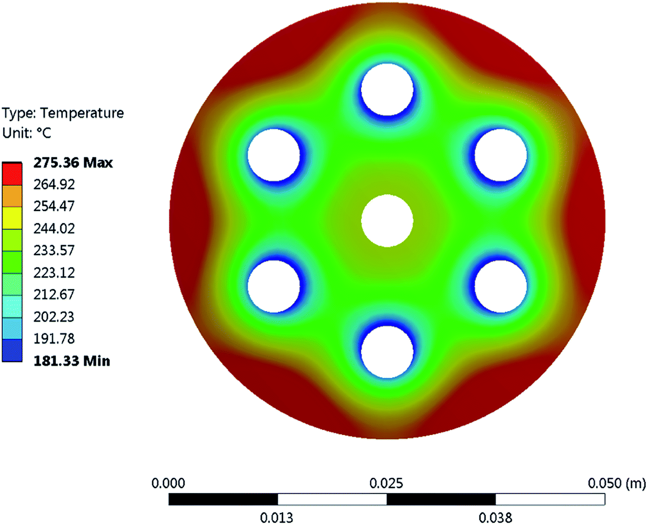
It is important to mention that the temperature shown as reactor temperature is only a representative value measured at a single point in the catalyst bed, as shown in Fig. 7 (left). In practice, large temperature gradients are present in the reactor because of the local chemical reaction releasing heat and the cooling tubes going directly through the catalyst bed. This is shown by a 2D simulation of the temperature distribution in the catalyst bed, as shown in Fig. 10. The steady state thermal simulation was performed using Ansys 18.2, where the catalyst bed is modelled as a full block of material with a bulk thermal conductivity of 1 W m−1 K−1, which is a typical value for this kind of arrangement.29 The volumetric heat generation is specified according to the enthalpy of reaction and convective boundary conditions corresponding to a flow rate of 1.2 g s−1 of cooling water are specified at the interface with the cooling tubes. The resulting temperature distribution shown in Fig. 10 is not expected to represent the exact temperature of the catalyst bed, but rather to qualitatively show the temperature gradients present in the reactor. It is indeed observed that a temperature difference of almost 100 °C exists within the catalyst. In the actual reactor, this behavior is expected to be further exacerbated due to inhomogeneous heat generation due to the spatial variation of the chemical reaction rate within the reactor. Nevertheless, a few interesting aspects are observed from these results. First of all, the existence of a maximum in the conversion as a function of the temperature is confirmed due to competing trends of kinetics and equilibrium, as shown from the thermodynamic model. The reactor temperature maximizing the conversion varies slightly depending on the space velocity and range from 220 °C to 260 °C. Second, a strong influence of the space velocity on the conversion is noticed. This trend is represented graphically in Fig. 11 at two different temperatures. It appears that the CO2 conversion for the methanation reaction decreases linearly with increasing space velocity. This behavior indicates that the conversion is limited by kinetics and not thermodynamics. The last very interesting observation from Fig. 9 is the fact that some points are beyond the equilibrium curve. This behavior can be explained by the fact that the temperature is measured at a single point in the catalyst bed. However, the catalyst bed is expected to have a temperature distribution with large gradients. The existing temperature variation within the reactor allows us to combine a high reaction rate in the hotter zone while benefiting from the high equilibrium conversion limit in the colder zones.
 |
| | Fig. 10 FEA simulation of the temperature distribution in the cross-section of the methanation reactor. It demonstrates the large temperature gradients within the chemical reactor. The outer surface of the chemical reactor was set to adiabatic, as heat losses through this surface are negligible. An adiabatic condition was also applied to the inner tube feeding the gas into the reactor, as no significant cooling occurs in that area. Finally, a convective boundary condition with a heat transfer coefficient of 140 W m−2 K−1 was applied. | |
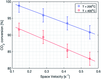 |
| | Fig. 11 CO2 conversion as a function of the space velocity. There is a linear decrease in the conversion with an increase in the space velocity. | |
Discussion
The chemical reactions and processes that allow producing synthetic hydrocarbons from hydrogen and carbon dioxide have the potential to play an important role in the energy turnaround. The Sabatier reaction is especially interesting as it produces methane with a high selectivity, which can be directly integrated into the existing natural gas infrastructure. As such, the chemical reactor developed and built at the Laboratory for Materials in Renewable Energy (LMER) at EPFL is of special interest. The reactor developed was able to reach a very high conversion of up to 99% at a temperature set point of 260 °C, a pressure of 5 bar and a space velocity of 0.14 s−1. A CO2 conversion of 97% was reached at a target flow rate of 50 g h−1 H2 at a temperature set point of 280 °C. It was found that the conversion varies linearly with the space velocity. Furthermore, the Mears criterion was calculated to be in the order of 10−5, which indicates that heat transfer is not the limiting step. Therefore, the process is limited by the kinetics rather than the thermodynamic equilibrium under the tested conditions. The obtained values are very close to – and in some cases even beyond – the theoretical thermodynamic equilibrium. This is explained by the inhomogeneous temperature distribution in the chemical reactor: while the temperature of the catalyst bed is measured at a single point, there is certainly a temperature distribution within the catalyst bed enabling the balancing of both kinetic and equilibrium aspects. This aspect will be further investigated and taken advantage of in future designs. Finally, no degradation of the catalyst was observed after a period of four months of usage. In the short-term future, the chemical reactor will be integrated into the Small-Scale Demonstrator Sion (SSDS), which is installed in the main building of EPFL Valais/Wallis. Furthermore, and based on the present results, a 10-fold upscale of the methanation reactor is in planning. This new reactor will also allow for waste heat recovery from the chemical reaction.
Conflicts of interest
There are no conflicts of interest to declare.
Nomenclature and abbreviations
|
E
a
| Activation energy [kJ mol−1] |
| FEA | Finite element analysis |
| FT-IR | Fourier transform infrared |
| HHV | Higher heating value |
|
k
0
| Pre-exponential factor Arrhenius |
|
k
f
| Forward reaction rate constant |
|
k
b
| Backward reaction rate constant |
| LMTD | Logarithmic mean temperature difference |
|
p
| Reactor pressure |
|
r
| Rate of reaction |
| SSDS | Small-scale demonstrator sion |
|
T
| Reactor temperature |
| TEM | Transmission electron microscopy |
|
v
s
| Space velocity |
Acknowledgements
The financial support from the Canton Valais, from the SCCER (CTI) Work Package Heat and Electricity Storage, from Gaznat SA and from Energie Sion Région (ESR) is gratefully acknowledged.
References
-
IEA, Key world energy statistics, 2016 Search PubMed
 .
.
-
T. F. Stocker
et al.
, Climate Change 2013: The Physical Science Basis. Contribution of Working Group I to the Fifth Assessment Report of the Intergovernmental Panel on Climate Change, IPCC, 2013 Search PubMed .
- H. Wirth and K. Schneider, Recent facts about photovoltaics in Germany, Rep. Fraunhofer Inst. Sol. Energy Syst. Ger., 2013 Search PubMed .
- A. Züttel, P. Mauron, S. Kato, E. Callini, M. Holzer and J. Huang, Storage of Renewable Energy by Reduction of CO2 with Hydrogen, CHIMIA International Journal for Chemistry, 2015, 69(5), 264–268 CrossRef PubMed , ISSN: 0009-4293.
- T. Schaaf, J. Grünig, M. R. Schuster, T. Rothenfluh and A. Orth, Methanation of CO2-storage of renewable energy in a gas distribution system, Energy, Sustainability and Society, 2014, 4(1), 2 CrossRef , ISSN: 2192-0567.
- S. Rönsch,
et al., Review on methanation – From fundamentals to current projects, Fuel, 2016, 166, 276–296 CrossRef .
- W. Wang, S. Wang, X. Ma and J. Gong, Recent advances in catalytic hydrogenation of carbon dioxide, Chem. Soc. Rev., 2011, 40(7), 3703–3727 RSC .
- S. Kattel, P. Liu and J. G. Chen, Tuning Selectivity of CO2 Hydrogenation Reactions at the Metal/Oxide Interface, J. Am. Chem. Soc., 2017, 139(29), 9739–9754 CrossRef CAS PubMed .
- N. Gallandat, J. Bérard, F. Abbet and A. Züttel, Small-scale demonstration of the conversion of renewable energy to synthetic hydrocarbons, Sustainable Energy Fuels, 2017, 1748–1758 CAS .
- F. Marechal, D. Favrat and E. Jochem, Energy in the perspective of the sustainable development: The 2000 W society challenge, Resour., Conserv. Recycl., 2005, 44(3), 245–262 CrossRef .
- J. Gao, Q. Liu, F. Gu, B. Liu, Z. Zhong and F. Su, Recent advances in methanation catalysts for the production of synthetic natural gas, RSC Adv., 2015, 5(29), 22759–22776 RSC .
- V. M. Shinde and G. Madras, CO methanation toward the production of synthetic natural gas over highly active Ni/TiO2 catalyst, AIChE J., 2014, 60(3), 1027–1035 CrossRef CAS .
- M. A. A. Aziz, A. A. Jalil, S. Triwahyono and A. Ahmad, CO2 methanation over heterogeneous catalysts: recent progress and future prospects, Green Chem., 2015, 17(5), 2647–2663 RSC .
- G. Garbarino, P. Riani, L. Magistri and G. Busca, A study of the methanation of carbon dioxide on Ni/Al2O3 catalysts at atmospheric pressure, Int. J. Hydrogen Energy, 2014, 39(22), 11557–11565 CrossRef CAS .
- H. Muroyama,
et al., Carbon dioxide methanation over Ni catalysts supported on various metal oxides, J. Catal., 2016, 343, 178–184 CrossRef CAS .
- S. Huanling, Y. Jian, Z. Jun and C. Lingjun, Methanation of carbon dioxide over a highly dispersed Ni/La2O3 catalyst, Chin. J. Catal., 2010, 31(1), 21–23 CrossRef .
- A. Borgschulte,
et al., Sorption enhanced CO2 methanation, Phys. Chem. Chem. Phys., 2013, 15(24), 9620–9625 RSC .
- G. Zhou, T. Wu, H. Xie and X. Zheng, Effects of structure on the carbon dioxide methanation performance of Co-based catalysts, Int. J. Hydrogen Energy, 2013, 38(24), 10012–10018 CrossRef CAS .
- F. Mirzaei, M. Rezaei, F. Meshkani and Z. Fattah, Carbon dioxide reforming of methane for syngas production over Co–MgO mixed oxide nanocatalysts, J. Ind. Eng. Chem., 2015, 21, 662–667 CrossRef CAS .
- P. J. Lunde and F. L. Kester, Kinetics of carbon-dioxide methanation on a ruthenium catalyst, Pap. Am. Chem. Soc., 1972, 164, 11–27 Search PubMed .
- P. J. Lunde and F. L. Kester, Rates of methane formation from carbon dioxide and hydrogen over a ruthenium catalyst, J. Catal., 1973, 30(3), 423–429 CrossRef CAS .
- M. Schoder, U. Armbruster and A. Martin, Heterogen katalysierte Hydrierung von Kohlendioxid zu Methan unter erhöhten Drücken, Chem. Ing. Tech., 2013, 85(3), 344–352 CrossRef CAS .
- G. Garbarino, D. Bellotti, P. Riani, L. Magistri and G. Busca, Methanation of carbon dioxide on Ru/Al2O3 and Ni/Al2O3 catalysts at atmospheric pressure: catalysts activation, behaviour and stability, Int. J. Hydrogen Energy, 2015, 40(30), 9171–9182 CrossRef CAS .
- G. Garbarino, D. Bellotti, E. Finocchio, L. Magistri and G. Busca, Methanation of carbon dioxide on Ru/Al2O3: catalytic activity and infrared study, Catal. Today, 2016, 277, 21–28 CrossRef CAS .
- J. H. Kwak, L. Kovarik and J. Szanyi, CO2 reduction on supported Ru/Al2O3 catalysts: cluster size dependence of product selectivity, ACS Catal., 2013, 3(11), 2449–2455 CrossRef CAS .
- P. Sabatier, Hydrogénations et déshydrogénations par catalyse, Eur. J. Inorg. Chem., 1911, 44(3), 1984–2001 CAS .
-
M. W. Chase Jr, NIST-JANAF thermochemical tables, Part II, Cr–Zr, J. Phys. Chem. Ref. Data Monogr., 4th edn, 1998, vol. 9 Search PubMed .
-
J. W. Barnes, Statistical analysis for engineers and scientists: a computer-based approach, McGraw-Hill, Inc., 1994 Search PubMed .
- P. Harriott, Thermal conductivity of catalyst pellets and other porous particles: part I: review of models and published results, Chem. Eng. J., 1975, 10(1), 65–71 CrossRef CAS .
|
| This journal is © The Royal Society of Chemistry 2018 |

 ab,
Robin
Mutschler
ab,
Vincent
Vernay
ab,
Heena
Yang
ab and
Andreas
Züttel
ab,
Robin
Mutschler
ab,
Vincent
Vernay
ab,
Heena
Yang
ab and
Andreas
Züttel