Bifunctional electrocatalytic CoNi-doped manganese oxide produced from microdumbbell manganese carbonate towards oxygen reduction and oxygen evolution reactions†
Harnchana
Gatemala
 ,
Soracha
Kosasang
and
Montree
Sawangphruk
 *
*
Department of Chemical and Biomolecular Engineering, School of Energy Science and Engineering, Vidyasirimedhi Institute of Science and Technology, Rayong 21210, Thailand. E-mail: montree.s@vistec.ac.th
First published on 23rd March 2018
Abstract
Herein, a new, simple, and stabilizer-free chemical synthetic protocol of microdumbbell manganese carbonate used as a precursor for producing nanoporous metal-doped manganese oxides is reported. This is the first time that a new growth mechanism of manganese carbonate via an oriented attachment mechanism of crystalline manganese carbonate nanospheres using its ferromagnetic property is revealed. The co-precipitation of divalent metal ions can be employed for the synthesis of metal-doped manganese carbonates. As-synthesized metal carbonates were employed as templates for producing porous metal-doped manganese oxides by calcination at 500–900 °C. The retention of template morphologies and metal oxide phases can be controlled by varying the calcination temperature. Doping of manganese oxide by Co2+ and Ni2+ to form a trimetal oxide can improve the catalytic performances for the ORR and OER under alkaline conditions. In addition, the trimetal oxide shows exceptional stabilities of 95.1% and 99.6% relative current retention for the ORR and OER at 40![[thin space (1/6-em)]](https://www.rsc.org/images/entities/char_2009.gif) 000 s, respectively. The catalyst produced in this work may be practically used towards the ORR and OER in many systems such as metal–air batteries.
000 s, respectively. The catalyst produced in this work may be practically used towards the ORR and OER in many systems such as metal–air batteries.
Introduction
As high energy-density batteries are needed for portable electronic devices, electric vehicles (EV), grid energy storage systems, etc., research interest has gradually shifted from Li-ion to metal–air batteries.1,2 Nevertheless, their widespread applications in the real-world devices have been greatly hindered by the sluggish kinetics of the oxygen reduction reaction (ORR) and oxygen evolution reaction (OER) which are the reactions taking place at the electrodes of metal–air batteries.3,4 Thus, the major challenge in this research area is to develop and design bifunctional electrocatalysts which are inexpensive, economically feasible, earth-abundant, highly efficient and environmentally friendly for the ORR and OER.3–5Although platinum and ruthenium oxide (RuO2) are known as the best ORR6 and OER7 catalysts, respectively, their practical uses for electrocatalysts have been limited by their scarcity, poor stability and high cost. The development of new catalysts which can overcome the current limitations of Pt and RuO2 is urgently required. Recent studies have demonstrated that transition-metal oxides could be employed as efficient bifunctional catalysts for the ORR and OER.
Transition metal oxides, which contain highly oxidized redox couples such as Co3+/4+, Ir4+/6+, Ru4+/8+, Fe3+/4+, Ni3+/4+ and Mn3+/4+, are well-known as active electrocatalysts for the ORR and OER. Among numerous metal oxides, manganese oxides, which are widely used in many applications such as magnetic materials,8 chemical sensors,9,10 catalysts,11–14 supercapacitors,15–18 and lithium ion batteries,19 have attracted much attention because of their various structures, low cost, environment-friendly nature, and low toxicity. For catalytic applications, manganese oxide shows effective catalytic performance as well as stability. Therefore, it could be a promising catalyst for metal–air batteries.
Doping of other metal ions into manganese oxide structures can improve their catalytic efficiencies.10,20,21 There are many reports on the synthesis of metal-doped manganese oxides such as refluxing,19 calcination of metal precursors,10,20,22,23 and in situ inclusion of doped-metal ions.24 Calcination of metal precursors such as metal carbonates and acetates employed as templates is a promising protocol for the synthesis of manganese oxides and metal-doped manganese oxide because their morphologies and compositions can be easily tuned by controlling the morphologies and compositions of the templates.
Manganese carbonate (MnCO3) has been considered for producing manganese oxide as well as metal-doped manganese oxide. Various morphologies of MnCO3 were successfully synthesized such as nanospheres,25,26 ellipsoidal nanostructures,27,28 dumbbells or peanuts,29–32 cubes,28,33–35 and flower-like microstructures22,36,37 using different approaches including ultrasonication,28,38 chemical precipitation,26,32,33 refluxing29 and hydrothermal process.22,27,30,34,36,37 Among these synthetic techniques, the hydrothermal process could be a promising technique since it provides a well-defined morphology and structure of the material. Also, experimental parameters such as reactant concentration, reaction temperature, reaction time and pH of the solution can be easily controlled by this method. Note, the morphology of the catalyst plays a vital role in catalytic efficiency.39–41 Hence, an in-depth understanding of the growth mechanism of MnCO3 templates is necessary because it can control the final morphology of manganese oxides.
In this work, the growth mechanism of MnCO3 and metal-doped MnCO3 is elucidated. This is the first report on the new growth mechanism of manganese carbonate via oriented attachment of crystalline manganese carbonate nanospheres by virtue of their ferromagnetic property. As-synthesized metal carbonate precursors were employed as templates for the synthesis of porous manganese oxides and metal-doped manganese oxides with template-morphology retention by the calcination process. Doping manganese carbonate with Co2+, Ni2+ or both in a chemical synthetic process can lead to the formation of bimetal and trimetal oxides after calcination. The as-calcined trimetal oxide exhibits the highest catalytic performances in the ORR and OER in an alkaline solution. Moreover, it shows excellent stability as compared to the well-known Pt and RuO2 catalysts.
Experimental
Chemicals
Potassium permanganate (KMnO4, purity ≥99%), cobalt nitrate hexahydrate (Co(NO3)2·6H2O, purity ≥98%), sodium hydroxide (NaOH, purity ≥97%) and potassium hydroxide (KOH, purity ≥85%) were purchased from Ajax Finechem. Nickel chloride hexahydrate (NiCl2·6H2O, purity ≥97%) and N-methyl-pyrrolidone (NMP, purity ≥99.5%) were purchased from QRëc. Tannic acid (C76H52O46) was obtained from Carlo Erba Reagents. Polyvinylidene fluoride (PVDF, MW 534,000) was obtained from Aldrich. All chemicals were used as received. Deionized (DI) water (Milli-Q, 15 MΩ cm) was used as a solvent. Prior to use, all glassware and magnetic bars were thoroughly cleaned with detergent, rinsed with DI water, rinsed with 6 M nitric acid, and thoroughly rinsed again with DI water.Synthesis of the manganese carbonate (MnCO3) template
MnCO3 was synthesized by the hydrothermal process. The formation of MnCO3 took place by the concerted reactions of KMnO4 reduction and precipitation by CO32− generated in situ by the oxidation of tannic acid. 5 g of KMnO4 was dissolved in 200 mL of DI water. The solution was vigorously stirred for 30 min. 2.5 g of tannic acid was dissolved in DI water. Subsequently, the pH of tannic acid solution was adjusted to 8 by the addition of 1 M NaOH and the final volume was adjusted to 200 mL. Tannic acid solution was gradually added into KMnO4 solution. The mixture was continuously stirred for 10 min before transferring into a 500 mL Duran bottle. The bottle was sealed and kept at 80 °C for 12 h in a hot air oven and allowed to cool naturally. After 12 h of hydrothermal process, the precipitates were separated by centrifuging at 12![[thin space (1/6-em)]](https://www.rsc.org/images/entities/char_2009.gif) 000 rpm, washing several times with DI water and drying at 60 °C for 24 h.
000 rpm, washing several times with DI water and drying at 60 °C for 24 h.
Synthesis of the metal-doped manganese carbonate (M–MnCO3) template
M–MnCO3 templates (M = Co, Ni and a mixture of Co and Ni) were synthesized using the same protocol as MnCO3 preparation. For the single metal doping process, Co(NO3)2·6H2O or NiCl2·6H2O with a Co or Ni![[thin space (1/6-em)]](https://www.rsc.org/images/entities/char_2009.gif) :
:![[thin space (1/6-em)]](https://www.rsc.org/images/entities/char_2009.gif) Mn molar ratio of 1
Mn molar ratio of 1![[thin space (1/6-em)]](https://www.rsc.org/images/entities/char_2009.gif) :
:![[thin space (1/6-em)]](https://www.rsc.org/images/entities/char_2009.gif) 2 was dissolved in KMnO4 solution while the bimetal doping process was carried out by dissolving Co(NO3)2·6H2O and NiCl2·6H2O in KMnO4 solution with a Co
2 was dissolved in KMnO4 solution while the bimetal doping process was carried out by dissolving Co(NO3)2·6H2O and NiCl2·6H2O in KMnO4 solution with a Co![[thin space (1/6-em)]](https://www.rsc.org/images/entities/char_2009.gif) :
:![[thin space (1/6-em)]](https://www.rsc.org/images/entities/char_2009.gif) Ni
Ni![[thin space (1/6-em)]](https://www.rsc.org/images/entities/char_2009.gif) :
:![[thin space (1/6-em)]](https://www.rsc.org/images/entities/char_2009.gif) Mn molar ratio of 1
Mn molar ratio of 1![[thin space (1/6-em)]](https://www.rsc.org/images/entities/char_2009.gif) :
:![[thin space (1/6-em)]](https://www.rsc.org/images/entities/char_2009.gif) 1
1![[thin space (1/6-em)]](https://www.rsc.org/images/entities/char_2009.gif) :
:![[thin space (1/6-em)]](https://www.rsc.org/images/entities/char_2009.gif) 4.
4.
Synthesis of manganese oxide (MnxOy) and metal-doped manganese oxide (M–MnxOy)
These metal oxides were prepared by the calcination of as-synthesized metal carbonate templates. Briefly, 2 g of MnCO3 or M–MnCO3 was put in a crucible. The samples were calcined at 500 °C, 700 °C and 900 °C for 5 h at a ramping rate of 5 °C min−1 in an air environment and allowed to cool naturally.Structural investigation
The morphology (size and shape) of the metal carbonate templates and metal oxides was recorded using a field emission scanning electron microscope (FE-SEM: JEOL, JSM-7001F) operating at 1 kV in high vacuum mode with a secondary electron image (SEI) detector. X-ray diffraction (XRD) patterns of all samples were recorded using a Bruker D8 ADVANCE instrument using Cu Kα radiation (40 kV, 40 mA) with a step size of 0.01° in the 2θ range of 5–80°. FT-IR measurements were carried out in the range of 400–4000 cm−1 (PerkinElmer).Electrochemical measurement
The cathode slurry was prepared by mixing 60 wt% of metal oxide powder, 30 wt% of carbon black as a conductive additive, and 10 wt% of polyvinylidene fluoride (PVDF) as a binder in N-methyl-pyrrolidone solvent. The slurry was then coated on a carbon fiber paper (CFP) substrate with an area of 1 × 1 cm2 using a casting machine (Gelon, Hong Kong) and dried at 60 °C overnight. The amount of active material loading in the cathode was ca. 0.3 mg cm−2. The electrocatalytic performances for the ORR and OER were measured in 0.1 M KOH with O2 bubbling using linear sweep voltammetry (LSV) and chronoamperometry with a computer-controlled μ-AUTOLAB II potentiostat (Eco-Chemie, Utrecht, The Netherlands) equipped with a FRA2 frequency response analyzer module and run on NOVA software (version 1.11). Electrochemical measurements were performed using a conventional three-electrode cell, including a platinum rod as the counter electrode, a saturated calomel electrode (SCE) as the reference electrode, and the catalyst-coated CFP as the working electrode.Results and discussion
After mixing tannic acid solution into KMnO4 solution, the mixture turned into a gel and precipitated within 2 min. The solution color turned from purple to black within 5 min after mixing indicating the reduction of Mn7+. After the 12 h hydrothermal process, a dark brown solid precipitated while the supernatant was clear. Fig. 1A shows the morphology of the products. Uniform microdumbbell-like structures with the average size of 2 μm are obtained. The XRD pattern in Fig. 1B presents sharp diffraction peaks indicating the high crystallinity of this material at 2θ of 24.24°, 31.38°, 37.55°, 41.44°, 45.22°, 49.73°, 51.65°, 60.20°, 63.97° and 67.80° corresponding to (012), (104), (110), (113), (202), (024), (116), (122), (214), and (300) planes of a rhombohedral phase MnCO3 (JCPDS no. 44-1472), respectively.31,42 The crystallite size of MnCO3 calculated by the Scherrer equation based on the (104) plane is 17.24 nm, which is much smaller than that of microdumbbell MnCO3, as shown in Fig. 1A (SEM image). This indicates the assembly of small crystals to form larger structures. The FT-IR spectrum of the product prepared by the hydrothermal process, shown in Fig. 1C, also confirms the formation of MnCO3. The strong peaks at 724 and 860 cm−1 correspond to symmetric and asymmetric bending of CO32− while the peak at 1390 cm−1 represents the asymmetric stretching of CO32−.25,27,42,43 The broad peak at 3408 cm−1 is assigned to water molecules adsorbed onto MnCO3 particles.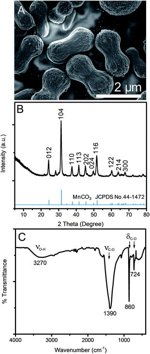 | ||
| Fig. 1 (A) SEM image, (B) XRD pattern and (C) FT-IR spectrum of MnCO3 after a 12 h hydrothermal process. | ||
Recently, there were many reports on the synthesis of MnCO3 dumbbell-like and peanut-like microstructures via the oxidation of various organic molecules such as sugar,34 urea,28,30 green tea extract,42N,N-dimethylformamide27 and L-ascorbic acid31 as the sources of carbonate ion by the hydrothermal process. All previous synthetic protocols required a high hydrothermal temperature of greater than 120 °C. Some protocols used an additional shape-controlling agent to control the morphology of MnCO3. In this work, it is the first time that tannic acid is used for the synthesis of MnCO3 without the addition of a shape-controlling agent at a much lower hydrothermal temperature of only 80 °C.
To the best of our knowledge, the growth mechanism of microdumbbell-like or peanut-like MnCO3 is well-known to be a magnetically driven self-assembly of nanoneedles31,32 or the transformation of assembled microcubes into hierarchical structures.42 To elucidate the growth mechanism of MnCO3 in this system, the structural evolution of MnCO3 was investigated by time-dependent SEM measurement. Fig. 2 exhibits the morphology of hydrothermally synthesized MnCO3 at different reaction times (after mixing tannic acid). After the addition of tannic acid, nanospheres with the average size of 10 nm are formed. Tannic acid is a polyphenol organic molecule which can act as a stabilizer to prevent the aggregation of formed particles for nanoparticle synthesis due to its oxygen containing functional groups. Therefore, the formation of very small nanoparticles in this system could be due to the stabilization by tannic acid. The size of the nanospheres increases to 20 nm when the reaction time is prolonged to 30 min. The average size of the nanospheres is close to the crystallite size calculated by the Scherrer equation. These nanospheres aggregate to form irregular shaped microparticles after a 1 h hydrothermal process. After the addition of tannic acid for 3 h, microdumbbell-like structures are observed. The size of the microdumbbells increases to 3 μm. There is no significant change after 6 h. Fig. 3 shows XRD patterns and FT-IR spectra of MnCO3 at different reaction times corresponding to the samples in Fig. 2. The characteristic XRD patterns and FT-IR peaks of MnCO3 are obviously observed after 3 h and unchanged after 6 h. This indicates that the formation of microdumbbell-like MnCO3 was complete within 6 h after the addition of tannic acid. Interestingly, nanoneedles are not observed in our system. Therefore, the growth mechanism of MnCO3 in our system cannot be the same as in previous reports. Fig. S1† displays the evidence for the growth mechanism at the early stage of MnCO3 formation. It has been reported that MnCO3 exhibits a ferromagnetic behavior.31 The microdumbbell-like MnCO3 could have formed by the oriented attachment mechanism of crystalline nanospheres driven by the magnetic property.
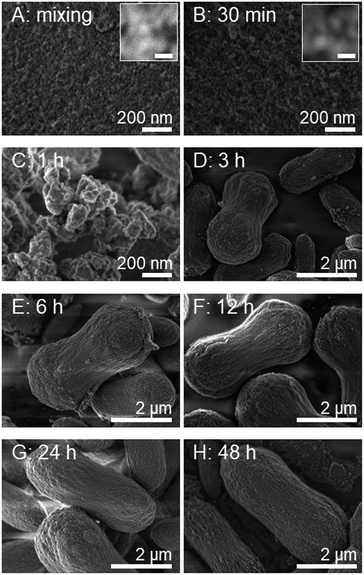 | ||
| Fig. 2 Time dependent SEM images show the morphological evolution of MnCO3 synthesized under the same conditions as that of Fig. 1. The time was recorded after the addition of tannic acid solution. Scale bars of inset images indicate 20 nm. | ||
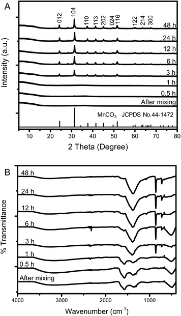 | ||
| Fig. 3 (A) XRD pattern and (B) FT-IR spectra at different reaction times of MnCO3 synthesized by the hydrothermal process. | ||
The assembly of nanospheres (∼20 nm) by the oriented attachment mechanism results in the formation of chain-like MnCO3 observed at the surface of microdumbbell-like structures (Fig. S3 and S4†). The growth mechanisms of MnCO3 and metal-doped MnCO3via the oriented attachment of nanorods or nanoneedles have been reported.22,37,44,45 However, the proposed growth mechanism of MnCO3 in our system has never been reported.
Based on these experimental results, the growth mechanism of microdumbbell-like MnCO3 is illustrated in Scheme 1. KMnO4 is reduced into Mn2+ by tannic acid (reaction (1)) while tannic acid is oxidized leading to the generation of CO2 (reaction (2)). CO2 dissolves in water and forms in situ generated CO32− (reaction (3)). Mn2+ reacts with the in situ generated CO32− while crystalline MnCO3 nanospheres (reaction (4)) are formed as primary structures.32 The formed nanospheres are stabilized by the excess tannic acid. After that, nanospheres attach to each other and form secondary structures via an oriented attachment mechanism driven by the ferromagnetic property. The oriented attachment of primary structures on secondary structures proceeds until crystalline MnCO3 nanospheres are depleted.
 | (1) |
 | (2) |
| CO2 + H2O → 2H+ + CO32− | (3) |
| Mn2+ + CO32− → MnCO3 | (4) |
As-synthesized microdumbbell-like MnCO3 was employed as the template for the preparation of manganese oxide by the calcination process. Fig. 4 exhibits the morphologies and XRD patterns of the calcined products. After calcination in an air environment for 5 h, MnCO3 is decomposed and forms cubic-phase Mn2O3 (JCPDS no. 65-7467) at the calcination temperature of 500–700 °C, which in good agreement with other reports.25,27,28 Mn2O3 shows porous morphology with the retention of microdumbbell-like MnCO3 templates. The average grain particle size of Mn2O3 increases from 30 to 150 nm when calcined at 500 °C and 700 °C, respectively (see in Fig. S2†). At the calcination temperature of 900 °C, tetragonal-phase Mn3O4 (JCPDS no. 24-0734) is obtained. However, the template morphology could not be retained. Microcrystals with the average particle size of 2 μm are observed. Therefore, the calcination temperature is the key parameter to control the morphologies and phases of manganese oxides.
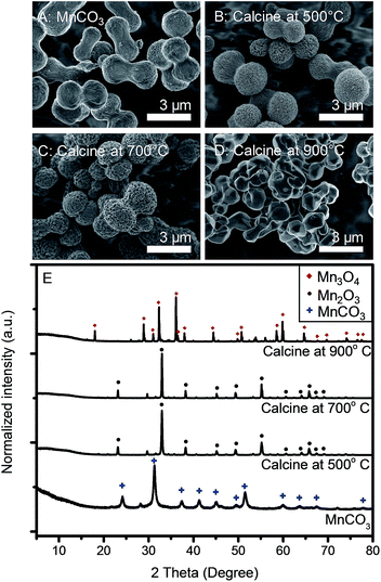 | ||
| Fig. 4 SEM images of (A) as-synthesized MnCO3, and the products after calcination at (B) 500 °C, (C) 700 °C and (D) 900 °C. (E) XRD patterns of samples corresponding to those of samples in (A–D). | ||
We hypothesized that metal ions, which can be precipitated by CO32−, could be doped into the MnCO3 structure by the co-precipitation process. In this work, Co2+ and Ni2+ were chosen as doping metal ions. Fig. 5 illustrates the morphologies of M–MnCO3. The morphologies of all samples are based on the structure of microdumbbell-like MnCO3. Thus, the growth mechanism of M–MnCO3 could be the same as MnCO3. The sizes of Co–MnCO3, Ni–MnCO3 and CoNi–MnCO3 are 2, 12 and 2 μm, respectively. Fig. S3–S5† display the morphologies and XRD patterns of M–MnCO3 before and after calcination at 500 °C, 700 °C and 900 °C for 5 h. Changes in the morphology and phase are observed. The products after calcination show porous morphology with the retention of template morphologies. However, at an extremely high calcination temperature of 900 °C, microcrystals are developed. The grain particle sizes increase with the increase of calcination temperature. Co–MnCO3 is decomposed and turns into the spinel tetragonal CoMn2O4 (t-CoMn2O4) after calcination as shown in Fig. S3.† The XRD patterns and the homogeneous elemental distribution of the calcination product in Fig. S3F–I† confirm that the synthesis presented in this paper is a highly efficient protocol for the preparation of Co-doped manganese oxide. The crystallinity of t-CoMn2O4 increases as the calcination temperature increases. At 500 °C and 700 °C, Ni–MnCO3 is decomposed into a mixture of Mn2O3, NiMnO3 and NiMn2O4 while at 900 °C, NiMn2O4 is the sole product as shown in Fig. S4.† EDS mapping also confirms the homogeneous distribution of Ni, Mn and O in the microdumbbell-like structures. For the bimetallic doping system, at 500 °C, the product is a mixture of nickel manganese cobalt oxide (NMC) spinel, Mn2O3 and NiMnO3. At 700 °C, the main products are NMC and Mn2O3. At a higher calcination temperature of 900 °C, CoNi–MnCO3 is decomposed into only NMC for which the XRD pattern in Fig. S5† corresponds to the NMC structure of a previous report.46 From the stoichiometry, NMC could be Co0.5Ni0.5Mn2O4. The crystallinity of Co0.5Ni0.5Mn2O4 increases with the increase of calcination temperature similar to CoMn2O4 samples.
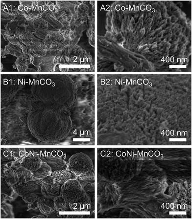 | ||
| Fig. 5 Low and high magnification SEM images of as-prepared (A) Co–MnCO3, (B) Ni–MnCO3 and (C) CoNi–MnCO3. | ||
Electrochemical performances
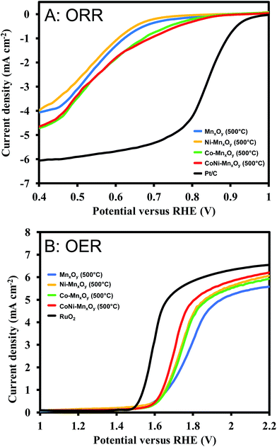
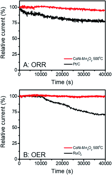
The ORR and OER were studied in 0.1 M KOH solution. For ORR measurements, O2 was bubbled into 0.1 M KOH solution for 40 min before performing the experiments. Fig. S6† illustrates the electrochemical performances of metal oxide catalysts in the ORR. It is clearly seen that the catalysts calcined at 500 °C show the best performance (highest onset potential) except for Co-doped manganese oxide in which case the sample calcined at 700 °C shows the best performance. Electrocatalytic performances for the OER in Fig. S7† show the same results as the ORR for which the catalysts calcined at 500 °C show the best performance (lowest onset potential) except for Co-doped manganese oxide. It is generally accepted that metal oxides calcined at higher temperatures have a higher degree of crystallinity. The higher degree of crystallinity results in lower catalytic activity but higher stability than low-temperature (amorphous) oxides. In other words, amorphous oxides exhibit higher activity but lower stability.47 Therefore, samples calcined at 500 °C, which have the lowest crystallinities, were chosen for comparison with benchmark commercial catalysts (Pt/C for the ORR and RuO2 for the OER). The bifunctional catalytic performances of manganese oxide and metal doped manganese oxides were determined as shown in Fig. 6. As expected, Pt/C shows the best electrocatalytic performance for the ORR with an onset potential of +0.908 V vs. RHE. Manganese oxide and Ni-doped manganese oxide show moderate performances with onset potentials of +0.652 and +0.656 V vs. RHE, respectively as shown in Fig. 6A. Doping Co2+ into the manganese oxide structure can obviously improve the electrocatalytic performance for the ORR (onset potential of +0.728 V vs. RHE). Interestingly, bimetallic-doped manganese oxide shows the best performance (onset potential of +0.735 V vs. RHE) among as-synthesized metal oxides which is not the direct combination of Co-doped manganese oxide and Ni-doped manganese oxide performances. We hypothesized that the improvement of the catalytic performances could be due to the synergistic effect of the two metal ions. Electrocatalytic performances for the OER are displayed in Fig. 6B. The results show that doping Ni2+ or Co2+ into the manganese oxide structure can significantly improve the electrocatalytic performances. The onset potentials decrease from +1.644 V vs. RHE of manganese oxide to +1.638 and +1.636 V vs. RHE for Co-doped manganese oxide and Ni-doped manganese oxide, respectively. In addition, bimetallic-doped manganese oxide also shows the best performance among these metal oxide catalysts (onset potential of +1.614 V vs. RHE). Nevertheless, the catalytic performances of all metal-doped manganese oxides are still lower than that of RuO2 (onset potential of +1.519 V vs. RHE).The stability of CoNi-doped manganese oxide was measured and compared with the benchmark commercial catalysts. The chronoamperometry technique was employed for this purpose. The electrocatalytic stabilities for the ORR were investigated at +0.7 V vs. RHE while those for the OER were measured at +1.7 V vs. RHE. The results are shown in Fig. 7. Although the electrocatalytic performances for the ORR and OER of CoNi-doped manganese oxide are lower than those of Pt/C and RuO2, their stabilities are much better than those of the benchmark commercial catalysts. At 40![[thin space (1/6-em)]](https://www.rsc.org/images/entities/char_2009.gif) 000 s after measurement of the ORR, Pt/C could retain only 77.3% of the relative current while CoNi-doped manganese oxide could retain 95.1%. With regard to the stability in the OER, RuO2 could retain 70.6% of the relative current at 40
000 s after measurement of the ORR, Pt/C could retain only 77.3% of the relative current while CoNi-doped manganese oxide could retain 95.1%. With regard to the stability in the OER, RuO2 could retain 70.6% of the relative current at 40![[thin space (1/6-em)]](https://www.rsc.org/images/entities/char_2009.gif) 000 s while CoNi-doped manganese oxide shows very stable relative current of 99.6%. Owing to the outstanding electrocatalytic stabilities of CoNi-doped manganese oxide in the ORR and OER, it could be one of the promising candidates for highly efficient bifunctional catalysts for metal–air batteries.
000 s while CoNi-doped manganese oxide shows very stable relative current of 99.6%. Owing to the outstanding electrocatalytic stabilities of CoNi-doped manganese oxide in the ORR and OER, it could be one of the promising candidates for highly efficient bifunctional catalysts for metal–air batteries.
Conclusions
A hydrothermal process for the synthesis of manganese carbonate was successfully developed. The developed synthetic protocol is a facile, highly efficient, environmentally friendly, low temperature and stabilizer-free process which can be applied for large scale production. In situ generated CO32− from the oxidation of tannic acid is the key parameter that controls the microdumbbell-like morphology of manganese carbonate. A new growth mechanism of manganese carbonate via the oriented attachment of crystalline manganese carbonate nanospheres by virtue of its ferromagnetic property was revealed. The developed synthetic protocol can also be applied for metal doping processes in manganese carbonate structures via the co-precipitation reaction. Metal carbonates were employed as templates for the preparation of manganese oxides and metal-doped manganese oxides for which their morphologies and phases can be tuned by adjusting the calcination temperature. Bimetal-doped (Co2+ and Ni2+) manganese oxide can significantly improve the catalytic performances of the ORR and OER under alkaline conditions. In addition, the bimetal-doped manganese oxide shows excellent stabilities with 95.1% and 99.6% retention of relative current for the ORR and OER at 40![[thin space (1/6-em)]](https://www.rsc.org/images/entities/char_2009.gif) 000 s. The catalyst in this work may be practically used towards the ORR and OER in many systems such as metal–air batteries.
000 s. The catalyst in this work may be practically used towards the ORR and OER in many systems such as metal–air batteries.
Conflicts of interest
There are no conflicts to declare.Acknowledgements
This work was financially supported by the Thailand Research Fund and Vidyasirimedhi Institute of Science and Technology (RSA5880043). Support from the Frontier Research Centre at VISTEC is also acknowledged.Notes and references
- J.-S. Lee, S. Tai Kim, R. Cao, N.-S. Choi, M. Liu, K. T. Lee and J. Cho, Adv. Energy Mater., 2011, 1, 34–50 CrossRef CAS.
- J. Zhang, Z. Zhao, Z. Xia and L. Dai, Nat. Nanotechnol., 2015, 10, 444 CrossRef CAS PubMed.
- J. Suntivich, K. J. May, H. A. Gasteiger, J. B. Goodenough and Y. Shao-Horn, Science, 2011, 334, 1383–1385 CrossRef CAS PubMed.
- Y. Liang, Y. Li, H. Wang, J. Zhou, J. Wang, T. Regier and H. Dai, Nat. Mater., 2011, 10, 780 CrossRef CAS PubMed.
- M. W. Kanan and D. G. Nocera, Science, 2008, 321, 1072–1075 CrossRef CAS PubMed.
- Y. Nie, L. Li and Z. Wei, Chem. Soc. Rev., 2015, 44, 2168–2201 RSC.
- S. Cherevko, S. Geiger, O. Kasian, N. Kulyk, J.-P. Grote, A. Savan, B. R. Shrestha, S. Merzlikin, B. Breitbach, A. Ludwig and K. J. J. Mayrhofer, Catal. Today, 2016, 262, 170–180 CrossRef CAS.
- X.-F. Shen, Y.-S. Ding, J. Liu, Z.-H. Han, J. I. Budnick, W. A. Hines and S. L. Suib, J. Am. Chem. Soc., 2005, 127, 6166–6167 CrossRef CAS PubMed.
- M. Nogami, T. Maeda and T. Uma, Sens. Actuators, B, 2009, 137, 603–607 CrossRef CAS.
- C.-C. Kuo, W.-J. Lan and C.-H. Chen, Nanoscale, 2014, 6, 334–341 RSC.
- G. Qiu, H. Huang, S. Dharmarathna, E. Benbow, L. Stafford and S. L. Suib, Chem. Mater., 2011, 23, 3892–3901 CrossRef CAS.
- M. M. Najafpour, S. Heidari, E. Amini, M. Khatamian, R. Carpentier and S. I. Allakhverdiev, J. Photochem. Photobiol., B, 2014, 133, 124–139 CrossRef CAS PubMed.
- C.-H. Kuo, I. M. Mosa, A. S. Poyraz, S. Biswas, A. M. El-Sawy, W. Song, Z. Luo, S.-Y. Chen, J. F. Rusling, J. He and S. L. Suib, ACS Catal., 2015, 5, 1693–1699 CrossRef CAS.
- P. Wuamprakhon, A. Krittayavathananon, N. Ma, N. Phattharasupakun, T. Maihom, J. Limtrakul and M. Sawangphruk, J. Electroanal. Chem., 2018, 808, 124–132 CrossRef CAS.
- C. Tanggarnjanavalukul, N. Phattharasupakun, K. Kongpatpanich and M. Sawangphruk, Nanoscale, 2017, 9, 13630–13639 RSC.
- P. Iamprasertkun, C. Tanggarnjanavalukul, A. Krittayavathananon, J. Khuntilo, N. Chanlek, P. Kidkhunthod and M. Sawangphruk, Electrochim. Acta, 2017, 249, 26–32 CrossRef CAS.
- N. Phattharasupakun, J. Wutthiprom, P. Chiochan, P. Suktha, M. Suksomboon, S. Kalasina and M. Sawangphruk, Chem. Commun., 2016, 52, 2585–2588 RSC.
- M. Sawangphruk, P. Srimuk, P. Chiochan, A. Krittayavathananon, S. Luanwuthi and J. Limtrakul, Carbon, 2013, 60, 109–116 CrossRef CAS.
- C. Song, R. Li, F. Liu, X. Feng, W. Tan and G. Qiu, Electrochim. Acta, 2010, 55, 9157–9165 CrossRef CAS.
- A. Indra, P. W. Menezes, C. Das, D. Schmeißer and M. Driess, Chem. Commun., 2017, 53, 8641–8644 RSC.
- P. W. Menezes, A. Indra, N. R. Sahraie, A. Bergmann, P. Strasser and M. Driess, ChemSusChem, 2015, 8, 164–171 CrossRef CAS PubMed.
- P. Pal, S. K. Pahari, A. K. Giri, S. Pal, H. C. Bajaj and A. B. Panda, J. Mater. Chem. A, 2013, 1, 10251–10258 CAS.
- X. Han, T. Zhang, J. Du, F. Cheng and J. Chen, Chem. Sci., 2013, 4, 368–376 RSC.
- P. Ahuja, S. K. Ujjain, R. K. Sharma and G. Singh, RSC Adv., 2014, 4, 57192–57199 RSC.
- S. M. Pourmortazavi, M. Rahimi-Nasrabadi, A. A. Davoudi-Dehaghani, A. Javidan, M. M. Zahedi and S. S. Hajimirsadeghi, Mater. Res. Bull., 2012, 47, 1045–1050 CrossRef CAS.
- S. Huang, H. Wu, P. Chen, Y. Guo, B. Nie, B. Chen, H. Liu and Y. Zhang, J. Mater. Chem. A, 2015, 3, 3633–3640 CAS.
- L.-X. Yang, Y. Liang, H. Chen, Y.-F. Meng and W. Jiang, Mater. Res. Bull., 2009, 44, 1753–1759 CrossRef CAS.
- L.-X. Yang, Y.-J. Zhu, H. Tong and W.-W. Wang, Ultrason. Sonochem., 2007, 14, 259–265 CrossRef CAS PubMed.
- L. Zhang, T. Mei, X. Wang, J. Wang, J. Li, W. Xiong, Y. Chen and M. Hao, CrystEngComm, 2015, 17, 6450–6455 RSC.
- L. Wang, Y. Sun, S. Zeng, C. Cui, H. Li, S. Xu and H. Wang, CrystEngComm, 2016, 18, 8072–8079 RSC.
- Y. Tang, S. Chen, T. Chen, W. Guo, Y. Li, S. Mu, S. Yu, Y. Zhao, F. Wen and F. Gao, J. Mater. Chem. A, 2017, 5, 3923–3931 CAS.
- Y. Tang, Y. Lu and G. Luo, Ind. Eng. Chem. Res., 2017, 56, 10036–10043 CrossRef CAS.
- X. Q. Chen, H. B. Lin, X. W. Zheng, X. Cai, P. Xia, Y. M. Zhu, X. P. Li and W. S. Li, J. Mater. Chem. A, 2015, 3, 18198–18206 CAS.
- S. Devaraj, H. Y. Liu and P. Balaya, J. Mater. Chem. A, 2014, 2, 4276–4281 CAS.
- R. Liu, S. Zhao, M. Zhang, F. Feng and Q. Shen, Chem. Commun., 2015, 51, 5728–5731 RSC.
- S. Zhao, F. Feng, F. Yu and Q. Shen, J. Mater. Chem. A, 2015, 3, 24095–24102 CAS.
- H. Hu, J.-y. Xu, H. Yang, J. Liang, S. Yang and H. Wu, Mater. Res. Bull., 2011, 46, 1908–1915 CrossRef CAS.
- B. Gielen, Y. Thimmesch, J. Jordens, G. Janssen, L. C. J. Thomassen, T. Van Gerven and L. Braeken, Chem. Eng. Res. Des., 2016, 115, 131–144 CrossRef CAS.
- H. Gatemala, S. Ekgasit and P. Pienpinijtham, CrystEngComm, 2017, 19, 3808–3816 RSC.
- H. Gatemala, C. Thammacharoen and S. Ekgasit, CrystEngComm, 2014, 16, 6688–6696 RSC.
- H. Gatemala, C. Thammacharoen, S. Ekgasit and P. Pienpinijtham, CrystEngComm, 2016, 18, 6664–6672 RSC.
- Udayabhanu, S. Muralikrishna, B. Kishore, H. Nagabhushana, D. Suresh, S. C. Sharma and G. Nagaraju, New J. Chem., 2017, 41, 12854–12865 RSC.
- H.-K. Lee, D. Sakemi, R. Selyanchyn, C.-G. Lee and S.-W. Lee, ACS Appl. Mater. Interfaces, 2014, 6, 57–64 CAS.
- G. M. Thorat, H. S. Jadhav and J. G. Seo, Ceram. Int., 2017, 43, 2670–2679 CrossRef CAS.
- X. Niu, H. Wei, W. Liu, S. Wang, J. Zhang and Y. Yang, RSC Adv., 2015, 5, 33615–33622 RSC.
- R. Miao, J. He, S. Sahoo, Z. Luo, W. Zhong, S.-Y. Chen, C. Guild, T. Jafari, B. Dutta, S. A. Cetegen, M. Wang, S. P. Alpay and S. L. Suib, ACS Catal., 2017, 7, 819–832 CrossRef CAS.
- T. Reier, I. Weidinger, P. Hildebrandt, R. Kraehnert and P. Strasser, ECS Trans., 2013, 58, 39–51 CrossRef.
Footnote |
| † Electronic supplementary information (ESI) available: SEM images, EDS maps, XRD spectra and linear sweep profiles. See DOI: 10.1039/c8se00062j |
| This journal is © The Royal Society of Chemistry 2018 |


