A one-step laser process for rapid manufacture of mesoscopic perovskite solar cells prepared under high relative humidity†
Qian
Chen
 a,
Muhamad Z.
Mokhtar
 a,
Jack Chun-Ren
Ke
 bc,
Andrew G.
Thomas
 ab,
Aseel
Hadi
a,
Eric
Whittaker
b,
Michele
Curioni
a and
Zhu
Liu
 *a
*a
aSchool of Materials, The University of Manchester, Manchester, M13 9PL, UK. E-mail: zhu.liu@manchester.ac.uk; Tel: +44 (0)1613064845
bPhoton Science Institute, The University of Manchester, Manchester, M13 9PL, UK
cSchool of Physics and Astronomy, The University of Manchester, Manchester M13 9PL, UK
First published on 29th March 2018
Abstract
Mesoscopic perovskite solar cells (PSCs) containing a TiO2 mesoporous structure and a compact TiO2 film have reached the highest power conversion efficiency (PCE) and excellent stability among various PSC structures. However, conventional fabrication of the mesoscopic structure requires high-temperature heating processes that are considerably time-consuming. Current methods also make it difficult to fabricate integrated or multifunctional devices on the same substrate. Laser processing offers an opportunity to develop a rapid, localized and precise treatment without damaging the substrate or surrounding materials. Here, we demonstrate a rapid and localized one-step fiber laser process to generate both mesoporous and compact TiO2 films on tin-doped indium oxide (ITO) glass. The average PCE obtained for the PSCs by laser irradiation for 1 min, prepared under a high relative humidity of around 60% by a one-step deposition method, is equivalent to that by furnace treatment for 2 h. A fundamental understanding of the laser sintering mechanism using a fiber laser with a wavelength of 1070 nm has also been established. The use of the fiber laser with a wall-plug efficiency of over 40% offers an economically feasible, industrially viable solution to the challenge of rapid fabrication of mesoscopic PSCs and integration of multifunctional devices. In addition, it opens a novel route to manufacture tandem, patterned or aesthetic solar cells in the future.
1. Introduction
The utilization of solar energy, particularly photovoltaic (PV) technology, has been considered as a promising solution to tackle the major challenge of the finite supply of fossil fuels and global environmental issues.1 Recently, perovskite solar cells (PSCs) have become one of the hottest topics in the field of PV research due to their rapid increases of power conversion efficiency (PCE) beyond 22% and relatively low fabrication cost.2–5 To date, mesoscopic PSCs comprising a TiO2 mesoporous structure on a compact TiO2 film have achieved the highest efficiency and excellent stability among the various structures.6,7 It has been proved that the use of such TiO2 mesoporous scaffolds contributes to improved charge collection efficiency, lower hysteresis and better resistance to moisture.8–10However, fabrication of the TiO2 mesoscopic PSCs requires high temperature processes (>450 °C) and is extremely time consuming.4,10 Formation of the mesoporous and compact TiO2 films is also performed via a two-step process. Preparation of the TiO2 mesoporous structure is carried out in a furnace at 450–550 °C for 30 min to remove the organic binders and achieve sufficient interconnection between the TiO2 nanoparticles, while formation of the compact film also requires temperatures above 450 °C to transform the TiO2 from an amorphous phase to a crystalline form.4 These long high-temperature processes prevent the high throughput of PSCs and use of flexible substrates,11e.g. plastic substrates; at these temperatures, even glass substrates with large areas could bend irregularly.12 More importantly, an integral high-temperature heating process by conventional methods also prevents integration of multifunctional devices on the same substrate.12 So far, a number of alternative heating sources have been explored to replace conventional furnace sintering for fabrication of TiO2 mesoporous structures, including UV-irradiation,13 near infrared (NIR) heating,14 flame annealing15 and UV–ozone treatment.16
Lasers, as a state-of-the-art manufacturing tool, enable a local, precise, selective, flexible, non-contact, highly automated, low-cost and scalable fabrication process.17 They have been used in a number of PSC applications, including laser-assisted growth of perovskite films,18,19 laser-assisted deposition of NiO electrodes and compact TiO2 films.20,21 Moreover, in order to scale up PSC modules for commercialization, laser scribing has been successfully used for isolating transparent conductive oxide (TCO) and other layers of the PSCs with minimal dead areas.22–24
For laser heat treatment, laser sintering with various wavelengths and pulse widths has been studied in order to form the TiO2 mesoporous structure for dye sensitized solar cells (DSSCs).12,25,26 Compared to conventional furnace or other annealing methods, laser sintering with Nd:YAG lasers shows significant benefits. It allows the integration of DSSCs with different devices on the same substrates, which otherwise could be damaged by furnace sintering.17 Its local sintering feature can prevent the glass bending induced by conventional heating methods.12 It also allows the fabrication of the TiO2 mesoporous structure on plastic substrates for DSSCs.25,26 To date, to the best of our knowledge, no work has been reported on the use of laser heat treatment for the generation of both mesoporous and compact TiO2 films on TCO-glass in one-step.
In this work, we aim to develop a one-step, rapid fabrication technique to generate both mesoporous and compact TiO2 films on ITO-glass using a fiber laser with a 1070 nm wavelength and millisecond pulse width, without thermally damaging the ITO or the glass substrate. Compared to Nd:YAG lasers with wall-plug efficiencies of 2–3%,12 used in the studies described above, fiber lasers show a dramatically increased wall-plug efficiency of over 40%. In addition, the millisecond pulse width selected for this work is believed to be essential to produce efficient mesoscopic perovskite solar cells through effective sintering mechanisms for the TiO2 mesoporous structure.
2. Results and discussion
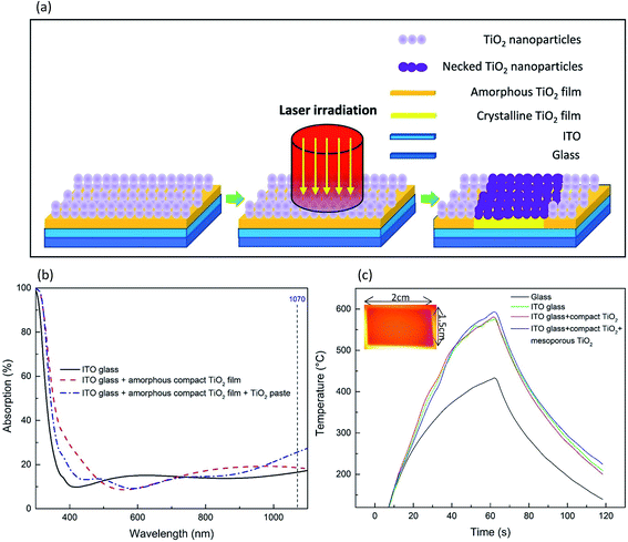
Fig. 1a illustrates the laser process schematically. Initially, titanium diisopropoxide bis(acetylacetonate) in 1-butanol and diluted 18 NRT TiO2 paste were spin-coated on the pre-cleaned ITO-glass and dried on a hotplate as described in the Experimental section. When the laser beam irradiated on the sample surface, the TiO2 paste containing TiO2 nanoparticles and the organic binders absorbed the laser beam partially, but a significant amount of the laser beam penetrated through the TiO2 paste, reaching the amorphous compact TiO2 film and the ITO. This was confirmed by the UV-visible spectra presented in Fig. 1b.To gain insight into the one-step laser process, various samples as described in Fig. 1c were irradiated with the fiber laser beam under the same processing conditions of 107 W cm−2 for 60 s, along with temperature monitoring by an IR thermal camera. In order to form an efficient necking of the TiO2 nanoparticles by furnace heating, a sintering temperature of at least 450 °C is normally required.27 As shown in Fig. 1c, the bare glass showed a peak temperature of 433 °C due to its low photo-thermal conversion.18,28 For the ITO-glass, the peak temperature was boosted to 584 °C due to the photon-induced excitation of the free charge carriers in ITO resulting in instantaneous local heating.28 Adding a thin amorphous compact TiO2 film (50 nm) on ITO-glass did not increase the peak temperature. Spin-coating a layer of TiO2 paste (150 nm) resulted in a peak temperature of 595 °C, due to stronger laser beam absorption of the TiO2 paste as evidenced in Fig. 1b. This implied that the sintering of the TiO2 paste and the crystallization of the compact TiO2 film were the result of the direct absorption of the laser beam by TiO2 paste, and a sufficient rise in temperature due to the contribution from the ITO film also enhanced the sintering effect and potentially improved the adhesion of the compact TiO2 films to the ITO film.
The temperature distribution obtained using an IR thermal camera as shown by the orange area in Fig. 1c was uniform across the whole sample surface (2 cm × 1.5 cm), demonstrating a unique feature of the fiber laser process developed in this work. Unlike the commonly used laser spot size of tens of micrometers and the use of a raster scan to cover the entire sample surface through overlapping laser tracks for DSSCs,12,17 the laser beam was defocused to achieve a spot size of 6.9 cm2 (i.e. 2.96 cm in diameter) in this work. A photograph of the laser processing set-up is shown in Fig. S1.† The large size of the laser beam offers a unique capability of rapid processing of PSCs to achieve a sintering process without rastering, which overcomes various drawbacks caused by overlapping laser beam tracks, such as re-heating, and reduces processing time in a highly simplified manner suitable for practical applications. Although the laser spot size was set to be larger than the sample area of 3 cm2, a mask with a customized area or shape could be applied to achieve local sintering of a specific area or shape of samples without damaging the surrounding areas.
Based on the calculations reported by Mincuzzi et al. on the use of a Nd:YAG laser for DSSCs, a processing time (tp) of 122 h by raster laser processing with an average power of 7 W was required, in comparison with 50 h and 6.25 h by hot-plate and furnace processes for sintering 1 m2 mesoporous TiO2 films.12 Under the existing laser processing conditions in this work, i.e. power density, pulse width and beam dimensions, both mesoporous and compact TiO2 films can be locally fabricated on 1 m2 ITO-glass in only 5.56 h (180 cm2 h−1). Therefore, this new laser process offers a significant improvement compared to the previous laser work on DSSCs. In addition, the previous work showed that the embodied energy for a Nd:YAG laser with a wall plug efficiency of 3.5% was lower than that of the hot plate, oven and furnace.12 The fiber laser used in this work has a wall-plug efficiency of over 40%. Therefore, the fiber laser process is believed to have greater potential for industrial applications, than processing using other types of lasers.12,17,26
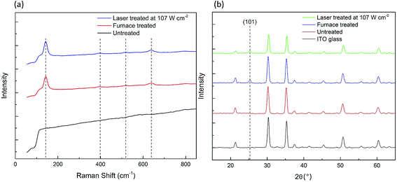
In the laser process, there are three critical temperatures required to achieve a successful sintering/crystallization of the TiO2 films. For the deposited TiO2 paste, a temperature of at least 280 °C is required to vaporize the organic binder, and ∼450 °C is needed for necking of the TiO2 nanoparticles to take place.29 For the amorphous compact TiO2 film, a temperature of 450 °C is essential for the crystallization of amorphous TiO2 to occur. Fig. 2a presents a comparison of the Raman spectra for the compact TiO2 film obtained by the furnace- and laser-treatment at 107 W cm−2 and with no treatment. Both the furnace- and laser-treated compact TiO2 films exhibit peaks at 144 cm−1 (Eg)*, 399 cm−1 (B1g)*, 519 cm−1 (B1g)*, and 639 cm−1 (Eg)*, corresponding to anatase TiO2 with tetragonal symmetry.30 This indicates that the laser processing successfully achieved the crystallization of the amorphous compact TiO2 film with no phase transformation to rutile. The X-ray diffraction (XRD) patterns of the laser-treated amorphous TiO2 compact film in Fig. 2b show a peak at 25.3°, corresponding to the (101) anatase phase, as further evidence for crystallization induced by the laser irradiation. The crystallinity of the TiO2 compact film is essential for high performance of PSCs, owing to the improved charge transport ability and electrical conductivity compared to the amorphous phase.31
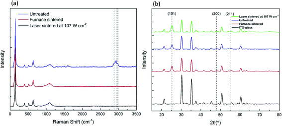
Raman spectra, shown in Fig. 3a, were also used to verify the complete removal of the organic binder within the TiO2 paste sintered by the furnace and the laser. The ethyl cellulose organic binder gives rise to Raman peaks at 2876 cm−1, 2934 cm−1 and 2976 cm−1, which were completely removed after sintering.13 Full removal of the organic binder is essential for efficient pore filling and improved electrical conductivity of TiO2 mesoporous structures.14Fig. 3a also shows that there was no phase transformation of the anatase TiO2 nanoparticles by laser sintering, which is further confirmed by the XRD patterns in Fig. 3b. All the samples show peaks at 25.3°, 48.2° and 55.1°, corresponding to the anatase planes at (101), (200) and (211).32
Fig. 4a–c show the high-resolution SEM images of the surfaces of the TiO2 mesoporous structures under different conditions. The TiO2 nanoparticles in the untreated film (Fig. 4a) were discrete, while the TiO2 mesoporous structure treated with the laser at 107 W cm−2 (Fig. 4c) and furnace (Fig. 4b) clearly revealed necking of the TiO2 nanoparticles and consequently an increase in the particle size due to the high temperature sintering. Efficient necking of the nanoparticles is essential to increase the diffusion length of the electrons for high performance PSCs.27
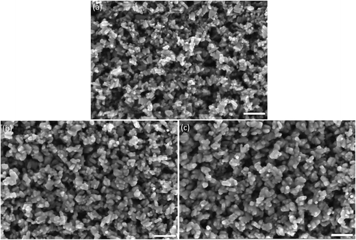 | ||
| Fig. 4 SEM images of top views of (a) untreated, (b) furnace- and (c) laser-treated TiO2 mesoporous structures at 107 W cm−2 (scale bar: 100 nm). | ||
The fiber laser process has several advantages over other alternative processes. For example, a recent publication demonstrated an interesting method of using near infrared (NIR) light to fabricate mp-TiO2/mp-ZrO2/carbon structure based perovskite solar cells with a PCE of 11% within only 30 s.14 Indeed, NIR processing is a promising method for rapidly manufacturing perovskite solar cells and shows a higher throughput than the laser process presented in this work. However, cracking along the standard laser patterned lines (isolating the FTO and glass) with a thickness of 1.4 mm in width was reported due to the large thermal stress induced by the significant temperature difference between the FTO and the glass during the rapid NIR process.14 Therefore, a thinner isolation line of 0.05 mm was applied to reduce the thermal stress between the glass and the FTO during the NIR irradiation. A similar issue was also observed when the fiber laser in continuous-wave mode and shorter irradiation time was applied by the authors. In this work, the formation of cracking was resolved by selecting the pulse-mode with a duty cycle of 100 ms ON/50 ms OFF under the same laser power density. The use of pulsed mode could prolong the period of time for thermal conduction between the glass and ITO, resulting in the reduction of temperature difference between the two layers compared to the continuous mode. Therefore, we have achieved the process without damaging the glass with a laser isolation line up to 2.15 mm. A schematic representation of laser-patterned ITO on glass is shown in Fig. S2.† We believe that the fiber laser process with selective pulse widths is a safer approach to conductive oxide coated glass substrates and could be applied to more circumstances for fabrication of PSCs such as aesthetic, patterned or customized cells with different patterned ITO or FTO layers.
In order to determine the quality of the prepared mesoporous and compact TiO2 films with regard to use in PSCs, prototype cells were fabricated. A cross-sectional view of the PSCs fabricated under a relative humidity of around 60% based on the configuration of ITO/cp-TiO2/mp-TiO2/perovskite/spiro-OMeTAD/Ag is shown in Fig. S3.† It has been well documented that a high humidity environment is particularly detrimental to the most commonly used lead-halide based perovskites CH3NH3PbI3 and CH3NH3PbI3−xClx for solar cell applications.33,34 An average PCE of 11% achieved in a glovebox was reduced to 0.35% in the fabrication environment with humidity over 60%.35 To achieve a high PCE, preparation of PSCs is mainly carried out in a highly controlled inert atmosphere.36 The use of an inert atmosphere is cost-ineffective and limits the mass-production and applications of PSCs. Although highly efficient PSCs with the PCEs up to 18% have been recently reported by a two-step deposition method at a high relative humidity of around 70%, the work also indicated that the device performance by a one-step deposition method was badly affected by moisture due to the uncontrollable crystallization process under the high humidity conditions.37
In this work, we have adapted the methods reported by Troughton, J. et al. and Ke, W. et al.,36,38 using a one-step deposition method with a molar ratio of 1![[thin space (1/6-em)]](https://www.rsc.org/images/entities/char_2009.gif) :
:![[thin space (1/6-em)]](https://www.rsc.org/images/entities/char_2009.gif) 1 of PbI2 to CH3NH3I and adding 5% Pb(SCN)2 into the precursor to prepare the perovskite precursor and ethyl acetate as an antisolvent in ambient air with a relative humidity of around 60%. It was reported that the use of ethyl acetate as an anti-solvent contributed to a better protection of the MAI–PbI2–DMSO intermediate phase during the spin-coating process under the high relative humidity conditions, compared to other antisolvents such as chlorobenzene, toluene or diethyl ether,36 so that an improved photovoltaic performance was achieved due to the better quality of the perovskite layer with fewer pinholes and defects and less variation of the grain sizes treated by ethyl acetate compared to other antisolvents.36 In addition, a small amount of Pb(SCN)2 additive was also reported to contribute to the increase of grain size of the perovskite layer, thus resulting in an improved photovoltaic performance.38
1 of PbI2 to CH3NH3I and adding 5% Pb(SCN)2 into the precursor to prepare the perovskite precursor and ethyl acetate as an antisolvent in ambient air with a relative humidity of around 60%. It was reported that the use of ethyl acetate as an anti-solvent contributed to a better protection of the MAI–PbI2–DMSO intermediate phase during the spin-coating process under the high relative humidity conditions, compared to other antisolvents such as chlorobenzene, toluene or diethyl ether,36 so that an improved photovoltaic performance was achieved due to the better quality of the perovskite layer with fewer pinholes and defects and less variation of the grain sizes treated by ethyl acetate compared to other antisolvents.36 In addition, a small amount of Pb(SCN)2 additive was also reported to contribute to the increase of grain size of the perovskite layer, thus resulting in an improved photovoltaic performance.38
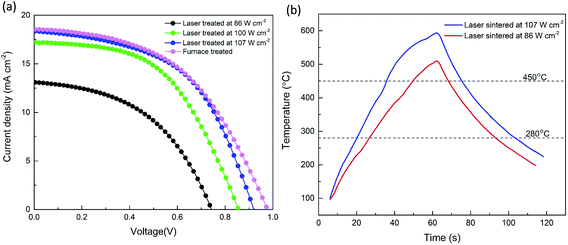
Fig. 5a shows the J–V curves under simulated solar irradiation of AM 1.5G (100 mW cm−2) of the PSCs fabricated with mesoscopic structures treated with the laser at different power densities, compared to a cell where the TiO2 films were treated in the furnace. It was found that increasing the laser power density from 86 W cm−2 to 107 W cm−2 remarkably improved the PCE from 4.5% to 8.8%. Increasing the power density also led to an increase in the recorded temperature on the TiO2 surfaces from 513 °C to 595 °C as shown in Fig. 5b. Following irradiation by the laser pulse the sample was found to remain at a temperature T > 450 °C for 18.9 s and 39.5 s and T > 280 °C for 66.3 s and 82.9 s for the 86 W cm−2 and 107 W cm−2 pulses, respectively. Since Raman spectra showed that the organic binders were completely removed, and crystallization of the compact TiO2 films occurred under all three laser conditions as shown in Fig. S4 and S5,† the difference in PCEs is believed to be related to the difference in the degree of interconnections between the TiO2 nanoparticles. As shown in Fig. S6,† at the higher laser power density, more efficient necking of TiO2 nanoparticles was achieved supporting the correlation between necking and higher PCEs. This is assumed to be linked to longer diffusion lengths of the electrons and fewer recombination reactions.39 However, with a further increase of the laser power density to 115 W cm−2, signs of superficial melting of the glass started to appear, which could adversely affect the performance of the devices.
Table 1 shows that a maximum PCE of 8.8%, with an average value of 8.2%, was achieved under the optimized laser processing condition of 107 W cm−2. This was comparable to the maximum PCE of 8.9% with an average value of 8.1% from the furnace process within experimental error. The J–V curves with forward and reverse scans for both furnace- and laser-treated samples are shown in Fig. S7a and b.† It is evident that the J–V curve with forward and reverse scans for the laser-treated sample (Fig. S7b†) presented a lower hysteresis than that for the furnace-treated sample (Fig. S7a†). This could be a result of the smoother and compact TiO2 film with better uniformity and fewer pinholes fabricated by the laser process (Fig. 6b) compared with that by the furnace process (Fig. 6a). A better quality of the compact TiO2 film is beneficial for a better transport of electrons from the mesoporous TiO2 film infiltrated with the perovskite to the compact film and ITO layer.40 The photovoltaic performance of the solar cells was relatively stable even with different scan rates as shown in Fig. S8.† This could, to some extent, indicate that the steady-state power output of the solar cell was relatively close to the J–V measurements.41 The PCEs obtained in this work with a one-step deposition method at a relative humidity of around 60% were comparable to several recent publications with one-step or even two-step deposition methods. Three examples can be given as follows: (1) a two-step method with a best PCE of 8.38% at 60% humidity,42 (2) a one-step method with a best PCE of 8.08% and an average PCE of 6.68% at a humidity of around 40%,43 and (3) an average PCE of 8.3% by a spray-casting method at a humidity of around 55%.44 A detailed chart with more recent publications with the comparable PCEs to our work is shown in Table S1.†
| Treatment | V oc [mV] | J sc [mA cm−2] | FF [%] | PCE best [%] | PCE average [%] | R s [Ω cm2] |
|---|---|---|---|---|---|---|
| Laser | 904 ± 23 | 18.2 ± 1.6 | 50.3 ± 5.8 | 8.8 | 8.2 ± 0.5 | 15.94 |
| Furnace | 960 ± 12 | 18.6 ± 0.4 | 45.6 ± 2.3 | 8.9 | 8.1 ± 0.5 | 20.11 |
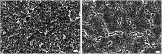 | ||
| Fig. 6 SEM images of top views of (a) furnace- and (b) laser-treated compact TiO2 films at 107 W cm−2 (scale bar: 100 nm). | ||
Another important observation shown in Table 1 is the difference in fill factors. The PSCs treated under the optimized laser conditions show a higher average fill factor of 50.3% than the furnace-treated ones with an average of 45.6%. This is more likely to be associated with the observation in Fig. 6, where the laser-treated TiO2 film exhibited better uniformity and fewer pinholes than the furnace-treated one. The smoother compact TiO2 film could contribute to the improved interfacial structure between the compact film and the mesoporous film infiltrated with the perovskite, thus reducing the recombination sites and increasing the charge transport at the interface resulting in an increase of the fill factor.45,46 Since the laser-treated TiO2 film showed fewer pinholes and defects, it may also contribute to a better conductivity of the compact film.41 This is in agreement with the results obtained in our work, in which the PSCs with the laser treatment had a lower overall series resistance of 15.94 Ω cm2 compared to 20.11 Ω cm2 for the furnace-treated ones. In addition, it has been reported that the resistivity of ITO increases significantly when a heating process at a temperature above 450 °C is applied for over 20 min.47 Therefore, we believe that another reason for higher series resistance of the furnace-treated devices was the heating process at >450 °C for more than 1 h, leading to degradation of the conductivity of the ITO layer. Compared to furnace processes, the heating period for the laser process over 450 °C was only 39.5 s which caused lower degradation of the ITO layer, thus also contributing to a lower overall series resistance. The average Voc of the furnace-sintered devices (960 ± 12 mV), on the other hand, was higher than that of the laser-sintered devices (904 ± 23 mV). This could be attributed to a small amount of Ti3+ present in the furnace-sintered TiO2 mesoporous structure, arising from surface O-vacancies.48 No Ti3+ was observed in the laser-sintered TiO2 mesoporous structure as shown in the Ti 2p XPS spectra in Fig. 7. It has been shown that the electronic defects existing within the TiO2 lattice can be passivated by a small amount of Ti3+,49 thus resulting in a higher Voc for the furnace-sintered TiO2 mesoporous structure than that of the laser sintered one.
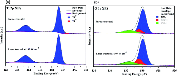 | ||
| Fig. 7 High resolution XPS spectra of (a) Ti 2p and (b) O 1s core levels recorded from the surfaces of the furnace- and laser-sintered mesoporous TiO2 films at 107 W cm−2. | ||
3. Conclusion
In summary, we have demonstrated a rapid and localized fabrication technique to generate both mesoporous and compact TiO2 films in one step for use in perovskite solar cells using a pulsed fiber laser with a wavelength of 1070 nm. With a stationary irradiation of 1 min at the optimized laser power density, crystallization of the amorphous compact TiO2 film, complete removal of the organic binders and necking of the TiO2 nanoparticles in the mesoporous structure have been successfully achieved. This laser process offers the advantages of localized fabrication, a significant reduction of processing time (from 2 h to 1 min), an increase in fill factor and a decrease of series resistance, over the furnace treatment. At a high relative humidity of up to 60%, an average PCE of 8.2% was achieved in prototype cells using the laser sintered semiconducting oxide support, identical to that produced using a furnace sintering approach. The fiber laser sintering mechanism has also been revealed through thermal analysis combined with UV absorption measurements for each individual layer involved in the photoanode structure of the PSCs. The use of the fiber laser with over 40% wall-plug efficiency opens a promising avenue for rapid fabrication of mesoporous and multi-layered metal oxide scaffold perovskite solar cells, as well as the potential for perovskite, dye- and quantum-dot sensitized solar cells fabricated in the form of integrated, multifunctional, tandem, patterned or aesthetic devices.4. Experimental section
Mesoscopic structure fabrication
The ITO-glass substrate (Ossila, 20 Ω sq−1) was cleaned in sequence with 2% Hellmanex solution in deionized water, acetone, and deionized water and then treated with UV–ozone for 15 min. A compact TiO2 layer was prepared by spin coating 0.1 M titanium diisopropoxide bis(acetylacetonate) (75 wt% in isopropanol, Sigma-Aldrich) solution in 1-butanol (Sigma-Aldrich) at 3000 rpm for 40 s on the ITO-glass and dried at 125 °C for 10 min. Then, the same process was repeated with 0.3 M titanium diisopropoxide solution in 1-butanol. The ITO-glass with the TiO2 precursor was sintered in a furnace with a 30 min ramp from room temperature to 500 °C and kept at 500 °C for 30 min, followed by natural cooling for 3 hours. Next, diluted TiO2 paste (Dyesol, 18NR-T) in ethanol at a 1![[thin space (1/6-em)]](https://www.rsc.org/images/entities/char_2009.gif) :
:![[thin space (1/6-em)]](https://www.rsc.org/images/entities/char_2009.gif) 4 weight ratio was spin-coated on the compact TiO2 layer at 4500 rpm for 30 s. The film was dried at 125 °C for 10 min and then the same process for sintering the compact layer was repeated.
4 weight ratio was spin-coated on the compact TiO2 layer at 4500 rpm for 30 s. The film was dried at 125 °C for 10 min and then the same process for sintering the compact layer was repeated.
One-step laser fabrication of the mesoscopic structure
After the spin coating of 0.1 M and 0.3 M compact titanium diisopropoxide in 1-butanol and drying at 125 °C for 10 min, diluted TiO2 paste was spin-coated and dried under the same conditions. The substrate was then placed on a ceramic plate on the laser workstation. An IPG fiber laser was employed for the sintering process. The laser beam with a uniform power density distribution of 86, 100, and 107 W cm−2 was applied. A pulse width of 100 ms with 50 ms of interval was used. The duration of laser irradiation on the substrate was set to 1 min. After the laser sintering process, the substrate was cooled down for 90 s to complete the fabrication process.Solar cell fabrication
To prepare the perovskite layer, 300 mg PbI2 (99.9%, Sigma-Aldrich), 104 mg CH3NH3I (98%, Sigma-Aldrich) and 10 mg Pb(SCN)2 (99.9%, Sigma-Aldrich) were mixed in 600 mg N,N-dimethylformamide (DMF, 99.8%, Sigma-Aldrich) and 150 mg dimethyl sulfoxide (DMSO, 99.9%, Sigma-Aldrich). The precursor was stirred at room temperature in ambient air for 1 hour. The precursor was spin-coated on the TiO2 mesoporous structure at 4000 rpm for 30 s and 0.2 ml of ethyl acetate (99.8%, Sigma-Aldrich) was dropped on the substrate at 8 to 9 s after the starting of the spin coating process. The film was then heated at 70 °C for 1 min and 100 °C for 10 min to obtain a CH3NH3PbI3 film. To prepare a 2,2′,7,7′-tetrakis(N,N-di-4-methoxyphenylamino)-9,9′-spirobifluorene (spiro-OMeTAD, 98%, Sigma-Aldrich) solution, 40 mg of spiro-OMeTAD was mixed with 10 μl of bis(trifluoromethane)sulfonamide lithium salt solution (520 mg ml−1 in acetonitrile) and 15 μl of 4-tert-butyl pyridine in 0.5 ml chlorobenzene (99.8%, Sigma-Aldrich). The spiro-OMeTAD solution was spin-coated on the perovskite layer at 3000 rpm for 30 s. Finally, 80 nm of Ag was deposited by using a thermal evaporator. The average relative humidity in the lab was measured to be around 70%. A dehumidifier was used to maintain a relative humidity of 60% during the entire fabrication process.Material and device characterization
The morphology of the TiO2 mesoporous structures and cross-sectional view of the PSC device were characterized by FEG-SEM (Ultra 55, Carl Zeiss). A Renishaw Raman Spectrometer with a 514 nm excitation Ar+ laser was used to characterize the crystallinity of compact TiO2 films and binder evaporation of the TiO2 mesoporous structure. A Bruker D8 Advance diffractometer (Cu-Kα) was used to characterize the phase transformation of compact and mesoporous TiO2 films. The surface chemistry of the TiO2 mesoporous structure was characterized by X-ray Photoelectron Spectroscopy (XPS, Kratos Axis Ultra). The absorption spectrum of ITO-glass and TiO2 paste on ITO-glass was measured using an UV-vis spectrophotometer (Shimadzu UV-2401PC). Current density–voltage (J–V) characteristics were measured using a solar simulator (Class AAA, Oreil) with one sun light intensity (100 mW cm−2) under 1.5G air mass calibrated using an NREL certified cell and a Keithley 2420 source meter. A square aperture mask with an area of 0.024 cm2 was used to define the active area. All characterization was performed in an ambient environment with a relative humidity of around 60%.Conflicts of interest
There are no conflicts of interest to declare.Acknowledgements
The authors would like to thank Mr Damian Crosby and Dr Wei Guo of the Laser Processing Research Centre (LPRC) of The University of Manchester for their technical support with laser operations.References
- L. K. Ono, N.-G. Park, K. Zhu, W. Huang and Y. Qi, ACS Energy Lett., 2017, 2(8), 1749–1751 CrossRef CAS.
- H. S. Jung and N. G. Park, Perovskite solar cells: From materials to devices, Small, 2015, 11, 10–25 CrossRef CAS PubMed.
- J. Jean, P. R. Brown, R. L. Jaffe, T. Buonassisi and V. Bulović, Energy Environ. Sci., 2015, 8, 1200 CAS.
- Q. Jiang, L. Zhang, H. Wang, X. Yang, J. Meng, H. Liu, Z. Yin, J. Wu, X. Zhang and J. You, Nat. Energy, 2016, 2, 16177 CrossRef.
- M. L. Petrus, J. Schlipf, C. Li, T. P. Gujar, N. Giesbrecht, P. Müller-Buschbaum, M. Thelakkat, T. Bein, S. Hüttner and P. Docampo, Capturing the Sun: A Review of the Challenges and Perspectives of Perovskite Solar Cells, Adv. Energy Mater., 2017, 7, 1700264 CrossRef.
- N.-G. Park, M. Grätzel, T. Miyasaka, K. Zhu and K. Emery, Nat. Energy, 2016, 1, 16152 CrossRef CAS.
- G. Grancini, C. Roldán-Carmona, I. Zimmermann, E. Mosconi, X. Lee, D. Martineau, S. Narbey, F. Oswald, F. De Angelis, M. Graetzel and M. K. Nazeeruddin, Nat. Commun., 2017, 8, 15684 CrossRef CAS PubMed.
- Y. Shi, Y. Xing, Y. Li, Q. Dong, K. Wang, Y. Du, X. Bai, S. Wang, Z. Chen and T. Ma, J. Phys. Chem. C, 2015, 119, 15868–15873 CAS.
- H. S. Kim and N.-G. Park, J. Phys. Chem. Lett., 2014, 5, 2927–2934 CrossRef CAS PubMed.
- J. Yang, K. M. Fransishyn and T. L. Kelly, Chem. Mater., 2016, 28, 7344 CrossRef CAS.
- F. Di Giacomo, A. Fakharuddin, R. Jose and T. M. Brown, Energy Environ. Sci., 2016, 9, 3007 CAS.
- G. Mincuzzi, M. Schulz-Ruhtenberg, L. Vesce, A. Reale, A. Di Carlo, A. Gillner and T. M. Brown, Prog. Photovoltaics, 2014, 22, 308 CAS.
- F. Di Giacomo, V. Zardetto, A. D'Epifanio, S. Pescetelli, F. Matteocci, S. Razza, A. Di Carlo, S. Licoccia, W. M. M. Kessels, M. Creatore and T. M. Brown, Adv. Energy Mater., 2015, 5, 1401808 CrossRef.
- J. Baker, K. Hooper, S. Meroni, A. Pockett, J. McGettrick, Z. Wei, R. Escalante, G. Oskam, M. Carnie and T. Watson, J. Mater. Chem. A, 2017, 5, 18643–18650 CAS.
- J. K. Kim, S. U. Chai, Y. Cho, L. Cai, S. J. Kim, S. Park, J. H. Park and X. Zheng, Small, 2017, 13, 1702260 CrossRef PubMed.
- B. Feleki, G. Bex, R. Andriessen, Y. Galagan and F. Di Giacomo, Mater. Today Commun., 2017, 13, 232–240 CrossRef CAS.
- G. Mincuzzi, L. Vesce, A. Reale, A. Di Carlo and T. M. Brown, Appl. Phys. Lett., 2009, 95, 103312 CrossRef.
- M. P. Arciniegas, A. Castelli, S. Piazza, S. Dogan, L. Ceseracciu, R. Krahne, M. Duocastella and L. Manna, Adv. Funct. Mater., 2017, 27, 1701613 CrossRef.
- F. Li, W. Zhu, C. Bao, T. Yu, Y. Wang, X. Zhou and Z. Zou, Chem. Commun., 2016, 52, 5394–5397 RSC.
- J. H. Park, J. Seo, S. Park, S. S. Shin, Y. C. Kim, N. J. Jeon, H. W. Shin, T. K. Ahn, J. H. Noh, S. C. Yoon, C. S. Hwang and S. Il Seok, Adv. Mater., 2015, 27, 4013 CrossRef CAS PubMed.
- B. Yang, M. Mahjouri-Samani, C. M. Rouleau, D. B. Geohegan and K. Xiao, Phys. Chem. Chem. Phys., 2016, 18, 27067–27072 RSC.
- G. D. Spyropoulos, C. O. Ramirez Quiroz, M. Salvador, Y. Hou, N. Gasparini, P. Schweizer, J. Adams, P. Kubis, N. Li, E. Spiecker, T. Ameri, H.-J. Egelhaaf and C. J. Brabec, Energy Environ. Sci., 2016, 9, 2302 CAS.
- S. J. Moon, J. H. Yum, L. Lofgren, A. Walter, L. Sansonnens, M. Benkhaira, S. Nicolay, J. Bailat and C. Ballif, IEEE J. Photovoltaics, 2015, 5, 1087 CrossRef.
- A. Fakharuddin, F. Di Giacomo, A. L. Palma, F. Matteocci, I. Ahmed, S. Razza, A. D'Epifanio, S. Licoccia, J. Ismail, A. Di Carlo, T. M. Brown and R. Jose, ACS Nano, 2015, 9, 8420 CrossRef CAS PubMed.
- H. Kim, R. C. Y. Auyeung, M. Ollinger, G. P. Kushto, Z. H. Kafafi and A. Piqué, Appl. Phys. A, 2006, 83, 73–76 CrossRef CAS.
- H. Pan, S. H. Ko, N. Misra and C. P. Grigoropoulos, Appl. Phys. Lett., 2009, 94, 071117 CrossRef.
- S. Nakade, M. Matsuda, S. Kambe, Y. Saito, T. Kitamura, T. Sakata, Y. Wada, H. Mori and S. Yanagida, J. Phys. Chem. B, 2002, 106, 10004 CrossRef CAS.
- T. Jeon, H. M. Jin, S. H. Lee, J. M. Lee, H. Il Park, M. K. Kim, K. J. Lee, B. Shin and S. O. Kim, ACS Nano, 2016, 10, 7907 CrossRef CAS PubMed.
- E. C. Muniz, M. S. Góes, J. J. Silva, J. A. Varela, E. Joanni, R. Parra and P. R. Bueno, Ceram. Int., 2011, 37, 1017 CrossRef CAS.
- L. Stagi, C. M. Carbonaro, R. Corpino, D. Chiriu and P. C. Ricci, Phys. Status Solidi B, 2015, 252, 124 CrossRef CAS.
- G. Yang, H. Tao, P. Qin, W. Ke and G. Fang, J. Mater. Chem. A, 2016, 4, 3970 CAS.
- S. Sathasivam, D. S. Bhachu, Y. Lu, N. Chadwick, S. A. Althabaiti, A. O. Alyoubi, S. N. Basahel, C. J. Carmalt and I. P. Parkin, Sci. Rep., 2015, 5, 10952 CrossRef CAS PubMed.
- Q. Tai, P. You, H. Sang, Z. Liu, C. Hu, H. L. W. Chan and F. Yan, Nat. Commun., 2016, 7, 11105 CrossRef CAS PubMed.
- J. Chun-Ren Ke, A. S. Walton, D. J. Lewis, A. Tedstone, P. O'Brien, A. G. Thomas and W. R. Flavell, Chem. Commun., 2017, 53, 5231 RSC.
- Z. Yang, C. C. Chueh, F. Zuo, J. H. Kim, P. W. Liang and A. K. Y. Jen, Adv. Energy Mater., 2015, 5, 1500328 CrossRef.
- J. Troughton, K. Hooper and T. M. Watson, Nano Energy, 2017, 39, 60 CrossRef CAS.
- Y. Cheng, X. Xu, Y. Xie, H.-W. Li, J. Qing, C. Ma, C.-S. Lee, F. So and S.-W. Tsang, Sol. RRL, 2017, 1700097 CrossRef.
- W. Ke, C. Xiao, C. Wang, B. Saparov, H. S. Duan, D. Zhao, Z. Xiao, P. Schulz, S. P. Harvey, W. Liao, W. Meng, Y. Yu, A. J. Cimaroli, C. S. Jiang, K. Zhu, M. Al-Jassim, G. Fang, D. B. Mitzi and Y. Yan, Adv. Mater., 2016, 28, 5214 CrossRef CAS PubMed.
- D. Zhao, T. Peng, L. Lu, P. Cai, P. Jiang and Z. Bian, J. Phys. Chem. C, 2008, 112, 8486 CAS.
- C. Huang, C. Liu, Y. Di, W. Li, F. Liu, L. Jiang, J. Li, X. Hao and H. Huang, ACS Appl. Mater. Interfaces, 2016, 8, 8520–8526 CAS.
- J. A. Christians, J. S. Manser and P. V. Kamat, Best practices in perovskite solar cell efficiency measurements. Avoiding the error of Making Bad Cells Look Good, J. Phys. Chem. Lett., 2015, 6, 852–857 CrossRef CAS PubMed.
- G. Murugadoss, H. Kanda, S. Tanaka, H. Nishino, S. Ito, H. Imahoric and T. Umeyama, J. Power Sources, 2016, 307, 891 CrossRef CAS.
- S. Prathapani, V. More, S. Bohm, P. Bhargava, A. Yella and S. Mallick, Appl. Mater. Today, 2017, 7, 112–119 CrossRef.
- D. K. Mohamad, J. Griffin, C. Bracher, A. T. Barrows and D. G. Lidzey, Adv. Energy Mater., 2016, 6, 1600994 CrossRef.
- B. Conings, L. Baeten, T. Jacobs, R. Dera, J. D'Haen, J. Manca and H. G. Boyen, APL Mater., 2014, 2, 081505 CrossRef.
- Z. Liu, Q. Chen, Z. Hong, H. Zhou, X. Xu, N. De Marco, P. Sun, Z. Zhao, Y.-B. Cheng and Y. Yang, ACS Appl. Mater. Interfaces, 2016, 8, 11076–11083 CAS.
- W. L. Hsu, Y. H. Pai, F. S. Meng, C. W. Liu and G. R. Lin, Appl. Phys. Lett., 2009, 94, 231906 CrossRef.
- M. J. Jackman, A. G. Thomas and C. Muryn, J. Phys. Chem. C, 2015, 119, 13682 CAS.
- F. Giordano, A. Abate, J. Pablo, C. Baena, M. Saliba, T. Matsui, S. H. Im, S. M. Zakeeruddin, M. K. Nazeeruddin, A. Hagfeldt and M. Graetzel, Nat. Commun., 2016, 7, 10379 CrossRef CAS PubMed.
Footnote |
| † Electronic supplementary information (ESI) available. See DOI: 10.1039/c8se00043c |
| This journal is © The Royal Society of Chemistry 2018 |

