Waste HD-PE plastic, deformation into liquid hydrocarbon fuel using pyrolysis-catalytic cracking with a CuCO3 catalyst†
Received
25th January 2018
, Accepted 8th March 2018
First published on 8th March 2018
Abstract
Waste high-density poly(ethylene) (HD-PE) plastic deformation into liquid hydrocarbon fuel using a pyrolysis-catalytic cracking process with a copper carbonate (CuCO3) catalyst, at a temperature range from 23 °C to 390 °C. The pyrolysis-catalytic deformation process will help in environmental purification. The liquid hydrocarbons collected for use as a fuel were analyzed using Fourier-transform infrared spectroscopy (FT-IR), nuclear magnetic resonance (NMR), thermogravimetric analysis (TGA), two-dimensional gas chromatography/time of flight mass spectrometry (2D-GCxGC/TOFMS), inductively coupled plasma (ICP) analysis, and carbon, hydrogen, nitrogen, sulfur, and oxygen (CHNS/O) elemental analysis. The 2D-GCxGC/TOFMS results showed that various types of hydrocarbon compounds (aliphatics, aromatics, cyclics olefins, and phenanthrene) were available in the liquid hydrocarbon fuel. The conversion rates in four experiments which converted waste HD-PE plastic into liquid hydrocarbons for use as fuel were 85%, 90%, 94%, 92%, light gases 14.67%, 9.66%, 5.64%, 7.45% and residues 0.33%, 034%, 0.36%, 0.55%. Liquid hydrocarbons as fuel were found to be appropriate for use in petrol and diesel engines and they were found to be a good source of organic compounds/petrochemicals.
1. Introduction
The annual global production of plastic materials from fossil fuel increased from 1.7 million tons in 1950 to 322 million tons in 2015. China was the largest producer (27.8%) in 2015, followed by the rest of Asia (including Japan) (21.0%), Europe (18.5%) and North American Free Trade Agreement (NAFTA) (18.5%).1 In Europe (EU28 + NO, CH) plastic production amounted to 58 million tons per year in 2015![[thin space (1/6-em)]](https://www.rsc.org/images/entities/char_2009.gif) 2 and 25.8 million tons of post-consumer plastic waste was produced in 2014. Thus, the treatment of post-consumer plastic waste is an important and increasing challenge. The seven types of common plastics are given in brackets with the percentage of European plastic demand for each polymer in 2014 (Plastics Europe, 2015): poly(propylene) [PP, (C3H6)n, 19.2%], low-density poly(ethylene) [(C2H4)n, 17.2%], high-density poly(ethylene) [HD-PE, (C2H4)n, 12.1%], poly(vinylchloride) [(C2H3Cl)n, 10.3%], polyurethane (C17H16N2O4, 7.5%), poly(ethylene terephthalate) [PET, (C108O4)n, 7.0%], and poly(styrene) [PS, (C8H8)n, 7.0%]. The European Union (EU) recommends a waste treatment hierarchy with the subsequent order of preference:3
2 and 25.8 million tons of post-consumer plastic waste was produced in 2014. Thus, the treatment of post-consumer plastic waste is an important and increasing challenge. The seven types of common plastics are given in brackets with the percentage of European plastic demand for each polymer in 2014 (Plastics Europe, 2015): poly(propylene) [PP, (C3H6)n, 19.2%], low-density poly(ethylene) [(C2H4)n, 17.2%], high-density poly(ethylene) [HD-PE, (C2H4)n, 12.1%], poly(vinylchloride) [(C2H3Cl)n, 10.3%], polyurethane (C17H16N2O4, 7.5%), poly(ethylene terephthalate) [PET, (C108O4)n, 7.0%], and poly(styrene) [PS, (C8H8)n, 7.0%]. The European Union (EU) recommends a waste treatment hierarchy with the subsequent order of preference:3
Preparing for reuse > recycling > recovery > landfill.
To date, in various countries landfill is still the first option for disposal of post-consumer plastic waste, and in 2014, 38% of the plastic waste was landfilled in the EU4 whereas 68.5% was landfilled in the US.5 As the use of various metals is being replaced by plastics,6 the amount of waste plastic is increasing because of the great demand for plastics.17 Plastics are not biodegradable and it can take 300–500 years for them to biodegrade.22 Presently, 39.5% of the plastic waste is being used for energy recovery, 29.7% of the waste is recycled and 30.8% is sent to landfill.35 Waste plastics recycling technology helps to avoid wastage of natural resources by utilizing waste plastics to get valuable energy rather than it being dumped elsewhere. Waste recycling technology is one of the most effective ways to minimize waste plastics. India has a large resource of manpower and technology7,8,22,39 and use of a plastic recycling system can create vast employment opportunities for millions of people. Waste plastic recycling can be further developed to ensure the safety of the environment.9 Pyrolysis-catalytic cracking is a chemical recycling technique whereby by using a suitable catalyst gives the capability to regulate the yield. When waste polymers together with the catalyst are degraded using the pyrolysis-catalytic method, it reduces the reaction temperature, and, increases the quantity and quality of the valuable product.17 There are several types of catalysts that have been tested in the conversion of vegetable oils into bio-gasoline and bio-diesel products such as molecular sieve catalysts, activated alumina catalysts, transition metal catalysts, and sodium carbonate.41 Different types of catalysts [fluid catalytic cracking (FCC), with Zeolite Socony Mobil-5 (ZSM-5) zeolite,10 silica, calcium carbide, alumina, magnesium hydroxide [Mg(OH)2], zinc oxide (ZnO), an heterogeneous mixture of silica and alumina,11 aluminium–zinc (Al–Zn) composite,12 mesoporous aluminium-Mobil Composition of Matter no. 41 (Al-MCM-41),13 two sulfate modified zirconium catalysts,14 DeLa ZSM-5 zeolite,15 HZSM-5 zeolite, silicon dioxide–alumina (SiO2–Al2O3, SAHA) and MCM-41 containing aluminium (MCM-41{Al}), and a mixture of MCM-41/HZSM-5 and SAHA/HZSM-5,16 HZSM-5 zeolite with photoionization,17 ZSM-11 zeolite and beta zeolites modified with Zn2+,18 Ni(SiO2),19 clay catalyst,20 magnesium carbonate (MgCO3),36 magnesium oxide (MgO)38] were used for the conversion of waste plastics into liquid hydrocarbon fuel. To acquire a comprehensive understanding of the waste plastic, pyrolysis-catalytic cracking technique, special analytical techniques were used to analyze the liquid hydrocarbon fuel and the raw plastics. Gas chromatograph/mass spectrometry (GC/MS) is a high sensible, provide smart performance for chemicals separation, therefore, sometimes utilized in the investigation of the product distribution over numerous catalysts.17,19,27–29 Analysis with GC/MS takes more time because of the sample preparation, adsorption, and extraction processes.17 Recently, laser and synchrotron-based gas chromatography, and two-dimensional gas chromatography/time of flight mass spectrometry (2D GCxGC/TOFMS) have been applied for the analytical studies of pyrolysis methods.32 The research described in this paper was directed at analyzing the catalytic conversation of waste HD-PE plastic into liquid hydrocarbon products using a copper carbonate (CuCO3) catalyst. The aim of this research was to obtain a high rate of conversion with a high liquid product yield at a low temperature. Pyrolysis-catalytic deformation provides an alternative for recycling waste HD-PE plastic, which is sustainable and cost-effective.
2. Materials and method
2.1 Materials
Waste HD-PE plastic (melting point = 138 °C, and density (ρ) = 0.965 g cm−3) was collected from native markets (Jhunjhunu, Rajasthan). The waste HD-PE plastic was separated by looking for the identification code 2, and plastic which was white and transparent. The collected waste HD-PE plastic was washed with caustic free, liquid detergent making it completely dust free and it was then dried in sunlight for 10 h. Dried waste HD-PE plastic was ground into small pieces of size <3–4 mm2 using a grinding machine.
2.2 Method
The systematic pyrolysis production process diagram is shown in Fig. 1. Dried, waste HD-PE plastic with different weight percentages (0% 2%, 5% and 8%) of CuCO3 [Central Drug House (CDH), New Delhi, India] was placed into a two liter, round shaped, Borosil commercial glass reactor (with a wall thickness of 3 mm). Then the glass reactor was placed in a fully insulated chamber of the furnace and an adapter was added to the glass reactor. Then, a coil condenser unit was added to the end of the adapter and the other end of the condenser lead into the liquid hydrocarbon fuel collection device. The temperature of furnace was controlled using an electronic temperature controller that maintained the temperature at a set point within a user specified tolerance by switching on and off appropriately. The maximum temperature, from a starting temperature of room temperature (23 °C), of 390 °C was achieved within 16 min. Solid waste HD-PE plastic in the glass reactor was converted into vapor which then passed through a glass reactor neck to the condenser, where it was collected as a liquid hydrocarbon fuel and this started to occur when the glass reactor was heated above 350 °C. Non-condensable gases were collected in the gas collection device, whereas the non-volatile char products were collected after the glass reactor was cooled to room temperature. The power supply for the experiment was 700 W. The yield of the liquid hydrocarbon fuel was calculated using the following equation:| |  | (1) |
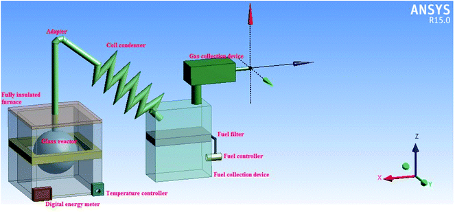 |
| | Fig. 1 Three-dimensional (3D) diagram of the production process for turning waste HD-PE plastic into liquid hydrocarbon fuel. | |
2.3 Analytical methods
A TGA 4000 thermogravimetric analyzer (Perkin Elmer) was used to investigate the thermal stability/degradation of waste HD-PE plastic using time and temperature. 2D-GCxGC/TOFMS was also performed using a Pegasus 4D (Leco Corporation). The 2D-GC technology developed has been useful for analyzing the liquid hydrocarbon fuel. For the 2D-GC both GC columns of different selectivities were coupled with a modulator. Split injection was used with a 4 mm Restek Siltek liner of Siltek wool (Fisher Scientific), and injection was 1 μl at 250 °C, the primary column was (30 m) × (0.25 mm × 0.25 μm) inner diameter (ID) × (0.1) μm film thickness (df), Restek Rtx-5 MS column (Fisher Scientific), the column was non-polar and separated all organic compounds using their boiling points. The secondary column was shorter, narrower and thinner 1 m × 0.1 mm ID × 0.1 μm df, Restek Rxi-17 (Fisher Scientific). The second column was more polar than the first column. Then both columns were housed in separate ovens in order to make it possible to vary the temperature control more. Constant helium gas was flowing (99.999%, 35 psi (2.4 bar) ± 10%), gas flow was 1.5 ml min−1, with a split ratio of 1![[thin space (1/6-em)]](https://www.rsc.org/images/entities/char_2009.gif) :
:![[thin space (1/6-em)]](https://www.rsc.org/images/entities/char_2009.gif) 150. The GCxGC oven program was: 70 °C held for 1.0 min, 10 °C min−1 to 280 °C, held for 5 min, and the temperature of the primary oven was offset by 35 °C and the secondary oven temperature was offset by 10 °C, with a total run time of 27.0 min. A modulation unit was located between both of the columns and it was the most important component of the 2D chromatography. The modulator occasionally sampled runoff from the initial column then automatically injected it into the next column. The 2D splitting was finished as soon as the next modulation started. All the chemicals were separated by two special columns, modulation period 4 s, hot pulse 0.9 s, cold pulse 1.1 s. The setup of the two columns ensured that the all 2D separation was finished before the one-dimensional (1D) analysis, the source temperature was 200 °C, the electron ionization was 70 eV, the mass range was 35 to 600 μ. The MS permitted accurate identification to be made for the whole of the chromatogram. Quadrupole mass spectrometers working in full scan mode were too slow to properly sample a GC × GC peak. However, TOFMS that work with spectral acquisition rates of 500 Hz were well suited for used with GC × GC. Nuclear magnetic resonance (NMR) spectroscopy with a 400 MHz instrument (Bruker) was used to analyze the correlation between carbon and proton atoms in liquid hydrocarbon fuel. Elemental analysis of liquid hydrocarbons was performed to determine the contents of carbon (C), hydrogen (H) and nitrogen (N) using a 24000 Series-II CHNS/O elemental analyzer (PerkinElmer). The functional groups of the liquid hydrocarbons and the waste HD-PE were determined using Fourier-transform infrared (FT-IR) spectrometry with an Alpha-T spectrometry (Bruker).
150. The GCxGC oven program was: 70 °C held for 1.0 min, 10 °C min−1 to 280 °C, held for 5 min, and the temperature of the primary oven was offset by 35 °C and the secondary oven temperature was offset by 10 °C, with a total run time of 27.0 min. A modulation unit was located between both of the columns and it was the most important component of the 2D chromatography. The modulator occasionally sampled runoff from the initial column then automatically injected it into the next column. The 2D splitting was finished as soon as the next modulation started. All the chemicals were separated by two special columns, modulation period 4 s, hot pulse 0.9 s, cold pulse 1.1 s. The setup of the two columns ensured that the all 2D separation was finished before the one-dimensional (1D) analysis, the source temperature was 200 °C, the electron ionization was 70 eV, the mass range was 35 to 600 μ. The MS permitted accurate identification to be made for the whole of the chromatogram. Quadrupole mass spectrometers working in full scan mode were too slow to properly sample a GC × GC peak. However, TOFMS that work with spectral acquisition rates of 500 Hz were well suited for used with GC × GC. Nuclear magnetic resonance (NMR) spectroscopy with a 400 MHz instrument (Bruker) was used to analyze the correlation between carbon and proton atoms in liquid hydrocarbon fuel. Elemental analysis of liquid hydrocarbons was performed to determine the contents of carbon (C), hydrogen (H) and nitrogen (N) using a 24000 Series-II CHNS/O elemental analyzer (PerkinElmer). The functional groups of the liquid hydrocarbons and the waste HD-PE were determined using Fourier-transform infrared (FT-IR) spectrometry with an Alpha-T spectrometry (Bruker).
3. Results and discussion
3.1 Characterization of waste HD-PE as pyrolysis feedstock
The thermogravimetry analysis (TGA) curve is shown in Fig. 2. HD-PE plastic degraded more between at 410 °C and 515 °C (under the inert atmosphere of pure nitrogen with a flow rate of 20 °C per min) because it was needed to measure pyrolysis thus, the instrument was set at 515 °C. This can be useful for investigating the thermal stability or the behavior of HD-PE in an inert atmosphere.
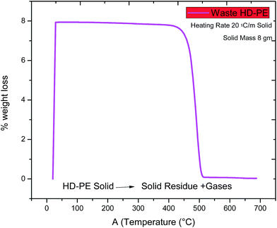 |
| | Fig. 2 Pre-analysis of waste HD-PE plastic using TGA. | |
The FT-IR spectra of waste HD-PE plastic is shown in Fig. 3. All the functional groups of waste HD-PE are made of hydrocarbons, therefore, they could be converted to liquid hydrocarbons. Methyl (–CH3) asym/sym stretch is functional group found at a wave frequency of 2914.44 cm−1, O–CH3, C–H stretch is functional group found at a wave frequency of 2846.93 cm−1, the methylene C–H bend is functional group found at a wave frequency 1462.04 cm−1, and a primary amine, C–N stretch is functional group found at a wave frequency of 1016.49 cm−1, 1,3 disubstitution (ortho) is functional group found at a wave frequency of 719.45 cm−1.
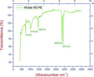 |
| | Fig. 3 Pre-analysis of waste HD-PE plastic using FT-IR. | |
3.2 Fuel properties of gasoline and diesel fractions
Tables 1 and 2 show the physical properties of liquid hydrocarbons from waste HD-PE, liquid hydrocarbons is yellowish color free from visible sediment. All properties of liquid hydrocarbons are found equal to ordinary fuel; therefore, it is the suitable for petrol/diesel engines. Total acid number (TAN) and total base number (TBN) properties of liquid hydrocarbons from HD-PE were measured by volumetric titration. When ash content, RBCR and copper strip corrosion for 3 h at 100 °C in liquid hydrocarbons the samples showed that the values were found equal to gasoline/diesel. Flash and fire point were slight higher to IS 1460-2005 standards. Kinematic viscosity at 40 °C and 100 °C measured by kinematic viscometer bath were results found 1.70 and 1.00. Density calculated by hydrometer was equal to regular diesel. Sulfur content 16.812 ppm is lower than regular gasoline/diesel but chlorine contents are absent, showing promising feature of low emission of sulfur dioxide during the use of liquid hydrocarbons a as fuel. Initial and final boiling point is equal to that of regular gasoline/diesel.
Table 1 Liquid hydrocarbon fuel from waste HD-PE analyzed by various test methods used for analyzing gasoline/diesela
| Parameter |
Requirement as per IS 1460-2005 |
Unit |
Test method |
Result |
Analytical instruments |
|
cSt: centistokes, ICP: inductively coupled plasma, KOH: potassium hydroxide.
|
| Total acid number |
Not specified |
mgKOH g−1 |
ASTM D664 |
2.13
|
Volumetric titration |
| Total base number |
Not specified |
mgKOH g−1 |
ASTM D2896 |
0.7
|
Volumetric titration |
| Ash content |
0.01 Max |
% by wt |
IS 1448 (P4) 2008 |
0.01
|
Muffle furnace |
| Ramsbottom carbon residue (RBCR, on 10% residue) |
0.30 Max |
% by wt |
IS 1448 (P8) 2008 |
0.028
|
RBCR |
| Copper strip corrosion for 3 h@100 °C |
Not worse than no. 1 |
|
IS 1448 (P15) 2004 ISO 2160:1998 |
1a
|
By copper bath |
| Flash point |
35 minimum |
°C |
IS 1448 (P20) 2007 |
37
|
Pensky–Martens (closed up) |
| Fire point |
50 minimum |
°C |
Nil |
52
|
Pensky–Martens (closed up) |
| Kinematic viscosity@40 °C |
Not specified |
cSt |
ASTM D445 |
1.70
|
Kinematic viscometer bath |
| Kinematic viscosity@100 °C |
Not specified |
cSt |
ASTM D445 |
1.00
|
Kinematic-viscometer bath |
| Density@15 °C |
820 to 890 |
g ml−1 |
IS 1448 (P32) 2008 |
86
|
Hydrometer |
| Sulfur content |
BSIII: 350 Max BSIV: 50 Max |
ppm |
ASTM D5185 |
16.812
|
ICP |
| Water content |
BSIII: not specified BSIV: 200 Max |
ppm |
ASTM D1744 |
344
|
Karl Fischer titrator |
| Particle counter |
Not specified |
|
ISO 4406 |
18/17/13
|
|
| Particle counter |
Not specified |
|
NAS 1638 |
9
|
|
| Chlorine content |
Not specified |
% by wt |
ASTM D808-05 |
Nil
|
Titration |
| Initial boiling point of fuel from HD-PE |
|
°C |
ASTM D86 |
131
|
Distillation apparatus |
| Final boiling point of fuel from HD-PE |
|
°C |
ASTM D86 |
325
|
Distillation apparatus |
Table 2 Distillation of recovered liquid hydrocarbons for use as fuel
| ml |
5 |
10 |
15 |
20 |
25 |
30 |
35 |
40 |
45 |
50 |
| °C |
148 |
151 |
159 |
169 |
179 |
191 |
205 |
222 |
244 |
252 |
| ml |
55
|
60
|
65
|
70
|
75
|
80
|
85
|
90
|
|
|
| °C |
269 |
281 |
290 |
298 |
305 |
310 |
314 |
316 |
|
|
Liquid hydrocarbon fuel from waste HD-PE was analyzed using inductively coupled plasma analysis (ICP) for 23 types of metals (Spectro GENESIS OES model) and the results of this are shown in Table 3, and were found to be less than those for gasoline/diesel. The petrol engine of a Splendor plus 2010 model motorcycle (Honda) was run using the liquid hydrocarbon fuel obtained from the waste HD-PE plastics. It was also shown that the fuel from the waste HD-PE can be used without any upgrading. Waste HD-PE plastic can chemically compared with fossil fuel. The fundamental chemical composition of fossil fuel was: C = 83–87%, H = 10–14% and the other rest N = 0.1–2%, S = 0.05–6%, metals <0.1%.21
Table 3 Liquid hydrocarbon fuel from waste HD-PE was analyzed for various metals in PPM
| S |
Cu |
Ca |
K |
Na |
Zn |
Cd |
Cr |
Mg |
Fe |
Si |
Al |
B |
Ti |
V |
Ni |
Mn |
Mo |
Sn |
P |
Pb |
Ba |
Ag |
| 16.812 |
0.008 |
0.013 |
0.854 |
1.154 |
0.113 |
0.003 |
0.008 |
00 |
0.011 |
0.056 |
0.242 |
2.49 |
0.004 |
0.019 |
0.017 |
0.00 |
0.035 |
0.073 |
2.35 |
0.165 |
00 |
0.017 |
The liquid hydrocarbon fuel can be formed from plastics, and it has fuel properties similar to crude oil.25 Waste HD-PE plastic typically contains C and H. Unlike bio-fuels, the absence of oxygen (O2) and the higher percentage of C and H content (Table 4) avoids the requirement of additional upgrading of the liquid hydrocarbon fuel. The absence of water, O2 and the low content of sulfur in the liquid hydrocarbon fuel gives it a very high calorific value (HCV).25,31,36 Therefore, conversion of these waste HD-PE plastics into utilizable liquid hydrocarbon fuel is increasing and this important field of study can potentially decrease the energy crisis as well as bringing commercial success.31 The calorific value of a hydrocarbon fuel is directly connected to the content of C. A high quantity of H element will additionally increase the calorific values of fuel.23 Therefore, the foremost issue that makes a suitable pyrolysis feedstock of plastic waste is the availability of carbon and hydrogen in waste HD-PE plastic with high energy contents which could be pyrolyzed and converted into liquid hydrocarbons for potential use as a fuel (Table 5).
Table 4 Chemical composition of waste HD-PE plastic, liquid hydrocarbons and its residue reported by various researchers
| Plastic |
Carbon (%) |
Hydrogen (%) |
Oxygen (%) |
Nitrogen (%) |
HCV (MJ kg−1) |
References |
| HD-PE |
83.9 |
14.09 |
0.74 |
— |
49.4 |
25
|
| HD-PE |
86.1 |
13 |
0.90 |
— |
46.4 |
30
|
| HD-PE |
86.24 |
12.95 |
0.05 |
— |
— |
10
|
| Bio-fuel |
80.1 |
13.5 |
5.3 |
1.1 |
|
40
|
| Waste HD-PE |
88.86 |
10.49 |
— |
0.08 |
— |
Present study |
| Residue of waste HD-PE |
58.67 |
5.95 |
— |
0.06 |
— |
Present study |
| Liquid hydrocarbon fuel |
89.51 |
10.2 |
— |
0.05 |
— |
Present study |
Table 5 Comparison of the yields of gases, liquids, and residues from HD-PE plasticsa
| Plastics used |
Catalyst |
Temperature (°C) |
Gas (wt%) |
Liquid (wt%) |
Residue (wt%) |
References |
|
LD-PE: low density poly(ethylene), Ni: nickel, Z: natural zeolite.
|
| HD-PE, LD-PE, PP, PS, PET |
Shwedaung clay |
210–380 |
21.78 |
65.81 |
12.41 |
[24]
|
| HD-PE, LD-PE, PP, PS, PET |
Mabisan clay |
210–380 |
19.92 |
67.06 |
13.02 |
[24]
|
| HD-PE, LD-PE, PP, PS, PET |
Bentonite clay |
210–380 |
21.86 |
64.92 |
13.22 |
[24]
|
| HD-PE, LD-PE, PP, PS, PET |
Dolomite |
210–380 |
28.52 |
63.96 |
7.52 |
[24]
|
| HD-PE, LD-PE, PP, PET |
Zinc oxide |
210–380 |
28.01 |
63.76 |
8.23 |
[24]
|
| HD-PE |
— |
440 |
9 |
74 |
17 |
[25]
|
| HD-PE |
HZSM-5 HY |
500 |
— |
58–70 |
— |
[26]
|
| Waste HD-PE |
Ni/Z |
450 |
68.27 |
30.74 |
1.10 |
[27]
|
| HD-PE-2 |
HZSM-5 |
370–420 |
5 |
90 |
5 |
[28]
|
| HD-PE |
— |
150–420 |
6 |
90 |
4 |
[29]
|
| Waste HD-PE |
MCM-41:ZSM-5 |
|
|
83.15 |
|
[34]
|
3.3 Mass yield recovery of gases, liquids and residues from waste HD-PE
Quantities of liquids, gases and residues from waste HD-PE plastics (100, 98, 95, 92 g) with different weight percentages (0, 2, 5, 8) of CuCO3 were determined as shown in Fig. 4. Waste HD-PE plastic whose rate of conversion into liquid hydrocarbon fuel was 85%, 90%, 94%, 92%, light gases 14.67% 9.66%, 5.64%, 7.45% and residues 0.33%, 034%, 0.36%, 0.55%. With the increase of percentage of the catalyst, the yield also increased compared to the results obtained without catalyst where the yield was less. Liquid hydrocarbon fuel from waste HD-PE plastics was characterized using a 2400 Series II CHNS/O elemental analyzer (PerkinElmer) and the results obtained were: C = 89%, H = 10.52%, N = 0.06%.
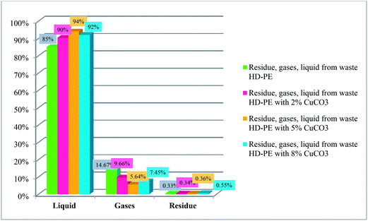 |
| | Fig. 4 Fractions collected from waste HD-PE plastics. | |
3.4 Deformation mechanism of waste HD-PE
Most of the work on catalysts for polymerization was done by Ziegler and Natta in early 1950s. A Ziegler–Natta catalyst is a complicated catalyst produce by reaction of transition metal compounds (alkyl, aryl, halide or derivatives of alkoxy) with a group IV–VIII transition metal such as cobalt (Co), chromium (Cr), molybdenum (Mo), nickel (Ni), rhodium (Rh), titanium (Ti), vanadium (V), or a metal alkyl and aryl halide of a group I–III metal such as aluminium (Al) which is a known co-catalyst.33 The CuCO3 catalyst plays an important role as it reduces the temperature and increases deformation of plastics using the pyrolysis process. The deformation of waste HD-PE plastic using CuCO3 is shown in Fig. 5 and in Fig. 6 also occurs via a carbenium ion mechanism. CuCO3 was breakdown to a CuO compound in the presence of heat in a reactor, CuO basic sites may create components of waste HD-PE plastic deformed via a carbenium mechanism, that causes an increase in the volume of olefins, carbenium of lower hydrocarbons comes in contact with one another to make cyclic or aromatic higher hydrocarbons.
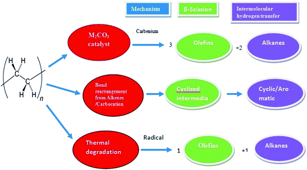 |
| | Fig. 5 Deformation mechanism of waste HD-PE plastic using pyrolysis-catalytic cracking over CuCO3. | |
 |
| | Fig. 6 Deformation mechanism of HD-PE over a base catalyst.36–38 | |
3.5 Chemical composition of liquid hydrocarbon
To further investigate the liquid hydrocarbon fuel obtained from the waste HD-PE plastic using a CuCO3 catalyst, 2D-GC chromatograms were visualized in a traditional 1D version, a 2D version with a contour plot and a 3D image in the surface plot, as shown in Fig. 7. This clearly shows the various types of chemical group in a specific area of the 2D plane such as mono-, bi- and poly-aromatics, paraffin, and cyclo-hydrocarbons. Table 6 shows the different types of hydrocarbon compounds that were found in the liquid hydrocarbon fuel using ChromaTOF software (LECO Corporation) and this offers a completely automated quantitative analysis for the use with GCxGC-TOFMS. The main chemical composition of liquid hydrocarbon fuel comprised of C9–C25 saturated hydrocarbons (9%), cyclic/branched (53%), aromatics as benzenes and naphthalenes (10%), phenanthrene (0.24%), unclassified (25%). Saturated hydrocarbons were nonane, 1-decane, and decane, branched/cyclic hydrocarbons were 1,2,3-trimethyl-, benzene, 1-ethenyl-2-methyl-, cyclopentene. Aromatic hydrocarbons were benzene, nepthalines, phenanthrene hydrocarbons and unclassified hydrocarbons. According to the retention time and signal-to-noise ratio (S/N) numbers (primary and secondary column), the compound with retention time 476, 0.920 and S/N number of 4420.7 is nonane, the compound with retention time 536, 1.020 and S/N number 3433.5, is benzene, 1-ethyl-3-methyl-, the compound with retention time 540, 1.110 and S/N number 2270.3, is benzaldehyde, the compound with retention time 552, 0.950 and S/N number 9899.6, is 1-decene, the compound with retention time 556, 0.980 and S/N number 3509.3, is bicyclo[5.3.0]decane, the compound with retention time 556, 1.040 and S/N number 25980, is benzene, 1-ethyl-4-methyl-, the compound with retention time 560, 0.940 and S/N number 13479, is decane, the compound with retention time 564, 0.980 and S/N number 2573.4, is cycloheptane, bromo- respectively. The yields of the liquid hydrocarbons were higher with CuCO3 catalyst than non-catalyst because temperature range was low and yields were higher. The gasoline and diesel range of lighter hydrocarbons was C5–C15 and this shows their potential to be used as transport-grade fuels. This is probably because of the occurrence of secondary reactions, for example, the Diels–Alder aromatization reaction changed a portion of the hydrogenated chains from aromatic compounds (e.g., benzenes) and the hydrocarbon chains could undergo a condensation reaction or dehydrogenation to produce aromatic compound (e.g., benzene derivatives). The possible thermal cracking reaction which occurred during the pyrolysis is shown next:42
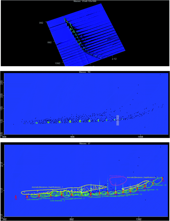 |
| | Fig. 7 Top: surface plot which shows a 1D version of the GC × GC chromatogram, middle: counter plot of GC × GC chromatogram, bottom: counter plot with labeled groups. | |
Table 6 Chemical composition of liquid hydrocarbon fuel from waste HD-PE plastic using a CuCO3 catalyst determined with GCxGC-TOFMS 1D chromatography
| Compound name |
Compound name |
Compound name |
Compound name |
| Nonane |
Benzene, 1,3-diethyl-5-methyl- |
Cyclopropane, 1-hexyl-2-propyl, cis- |
Benzene, 1-methyl-2-(1-ethylpropyl)- |
| Benzene, 1-ethyl-3-methyl- |
Penta-2-en-4-yne,-2,5-dicyclopropyl |
1H-Indene, 1-ethylideneoctahydro-, trans- |
Penta-2-en-4-yne,-2,5-dicyclopropyl |
| Benzaldehyde |
Benzene, 1-ethenyl-4-ethyl- |
Octane, 4-ethyl- |
Undecane |
| 1-Decene |
2-Ethyl-1-dodecanol |
Cyclopentene,1-hexyl- |
Naphthalene, 1,2,3,4-tetrahydro-2-methyl- |
| Bicyclo[5.3.0]decane |
1H-Indene, 2,3-dihydro-4,7-dimethyl- |
Benzene, (1-ethylbutyl)- |
1,13-Tetradecadiene |
| Benzene, 1-ethyl-4-methyl- |
Benzene, pentyl- |
Undecane, 2,4-dimethyl- |
Unknown 7 |
| Decane |
Benzene, 2,4-diethyl-1-methyl- |
1,Z-5,E-7-Dodecatriene |
Cyclodecane |
| Cycloheptane, bromo- |
Undecane, 3-methyl- |
Benzene, (1-ethyl-1-propenyl)- |
Cyclohexane, hexyl- |
| Benzene, 1,2,3-trimethyl- |
Cycloundecene(Z) |
Cyclopentene,1-heptyl- |
Anti-10-methyl-endo- |
| Benzene, 1-ethenyl-2-methyl- |
Benzene, 1,2,3,5-tetramethyl- |
1,10-Undecadiene |
Tricyclo[5.2.1.0(2.6)]decane |
| 2-Decyne |
1H-Indene, 2,3-dihydro-4-methyl- |
Benzaldehyde, 3-methyl- |
Cis, cis-2-ethylbicyclo[4.4.0]decane |
| Benzene, 1-methyl-2-(1-methylethyl)- |
Anti-10-methyl-endo- |
Benzene, 2-ethyl-1,4-dimethyl- |
3-Methylene-1,5,5-trimethylcyclohexene |
| Benzene, 1,2,3-trimethyl- |
Tricyclo[5.2.1.0(2.6)]decane |
Unknown 1 |
Benzene, 1-methyl-3-(1-methyl-2-propenyl)- |
| Cyclodecane |
Benzene, 1-butynyl- |
1-Undecene |
Dodecane |
| Oxalic acid, isobutyl nonyl ester |
1,12-Tridecadiene |
Undecane |
Unknown 6 |
| Cyclopentene, 1-butyl- |
Cyclododecene, (E)- |
Benzene, 1-methyl-2-(1-methylethyl)- |
Cyclohexene, 1-ethyl-4,5-divinyl- |
| Benzene, cyclopropyl- |
2,4-Octadiyne |
7-Propylidene-bicyclo[4.1.0]heptane |
1H-Indene, 1,3-dimethyl- |
| Decane, 2-methyl- |
Benzene, (1-methylbutyl)- |
Cyclohexane, 1-methyl-2-propyl- |
3-Dodecene, (E)- |
| 2-Undecyne |
1-Undecene, 2-methyl- |
Benzene, 1-butenyl-, (E)- |
1,13-Tetradecadiene |
| Benzene, 1-methyl-3-propyl- |
Unknown 4 |
2-Undecene, (Z)- |
Bicyclo[5.1.0]octane, 8-(1-methylethylidene)- |
| Bicyclo[3.2.1]oct-2-ene, 3-methyl-4-methylene- |
Benzene, 1-methyl-4-(1-methylpropyl)- |
5-Undecyne |
1H-Indene, 2,3-dihydro-1,2-dimethyl- |
| 1-Decene, 9-methyl- |
Unknown 5 |
Ethanone, 1-(2,5-dimethylphenyl)- |
Benzene, (1-methylpentyl)- |
| Benzene, 1-methyl-3-propyl- |
Naphthalene, 1,2,3,4-tetrahydro- |
Bicyclopentylidene |
Benzene, 1,3-diethyl-5-methyl- |
| 1-Decyne |
Cyclododecane |
Benzene, 1-methyl-2-(1-methylethyl)- |
2-Dodecene, (Z)- |
| Unknown 2 |
Cyclododecene, (E)- |
5-Undecene, (E)- |
Benzene, 1,4-diethyl-2-methyl- |
| Unknown 3 |
6,7-Dimethyl-1,2,3,5,8,8a- |
2-Undecyne |
Trans-cinnamyl bromide |
| Benzene, (2-methyl-2-propenyl)- |
Hexahydronaphthalene |
Octane, 5-ethyl-2-methyl- |
Naphthalene |
| 5-Ethyldecane |
1H-Indene, 2,3-dihydro-1,6-dimethyl- |
Benzene, 2-ethyl-1,3-dimethyl- |
Decane, 5-propyl- |
| 5-Decene, 4-ethynyl-, (E)- |
Bicyclo[6.1.0]nonane, 9-(1-methylethylidene)- |
|
|
Thermal cracking of hydrocarbons:
| |  | (R1) |
Dehydrogenations:
Diels–Alder aromatization:
| |  | (R3) |
More cyclic and aromatic hydrocarbons were collected than other hydrocarbons. Therefore, the calorific values of the fuel were increased because more carbon content was available in cyclic and aromatic hydrocarbons than in other hydrocarbons.
The functional groups of the liquid hydrocarbon fuel was determined using an ALPHA-T FT-IR instrument (Bruker). The functional groups according to wave numbers/frequency were: methyl (–CH3) functional group of wave frequency 2956.07, methylene C–H asym/sym bend functional group of wave frequency 2921.83 and 2853.04, alkenyl C![[double bond, length as m-dash]](https://www.rsc.org/images/entities/char_e001.gif) C stretch functional group of wave frequency 1641.51, methylene C–H bend functional group of wave frequency 1463.88, vinylidene C–H in plane bending functional group of wave frequency 1377.48, vinylidene C–H out of plane bending functional group of wave frequency 991.76, trans C–H out-of-plane bending functional group of wave frequency 965.28 cm−1, aromatic C–H out of plane bending functional group of wave frequency 908.91, 1,3 disubstitution (meta) functional group of wave frequency 888.17, 1,3 disubstitution (ortho) functional group of wave frequency 721.48 cm−1, and alkyne C–H bend functional group of wave frequency 632.59 (see Fig. 8).
C stretch functional group of wave frequency 1641.51, methylene C–H bend functional group of wave frequency 1463.88, vinylidene C–H in plane bending functional group of wave frequency 1377.48, vinylidene C–H out of plane bending functional group of wave frequency 991.76, trans C–H out-of-plane bending functional group of wave frequency 965.28 cm−1, aromatic C–H out of plane bending functional group of wave frequency 908.91, 1,3 disubstitution (meta) functional group of wave frequency 888.17, 1,3 disubstitution (ortho) functional group of wave frequency 721.48 cm−1, and alkyne C–H bend functional group of wave frequency 632.59 (see Fig. 8).
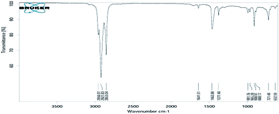 |
| | Fig. 8 FT-IR spectra of waste HD-PE plastic catalysed using CuCO3 to obtain liquid hydrocarbons. | |
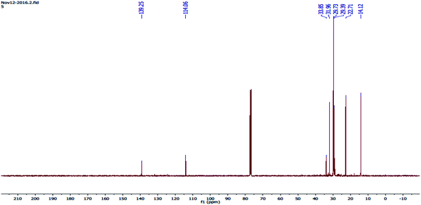
The 13C-NMR spectrum (Fig. 9) shows various chemical shifts (ppm) because of the combination of the different forms of carbon. Each carbon nucleus has its own chemical environment and because of the non-equivalent nuclei, it has a distinct magnetic field, and absorbs at totally different applied magnetic field strengths. In the 13C-NMR spectrum there was a signal at 14.12 and carbon as CH3 had a signal at 22.71 and carbon as CH2, had a signal at 29.39 and its methylenic carbon, had a signal at 29.73, carbon as CH2, had a signal at 31.96 and carbon as R3-C, had a signal at 33.85 and R3-CH carbon, had a signal at 139 and its carbon was in an aromatic ring.
 |
| | Fig. 9
13C-NMR spectra of waste HD-PE plastic catalysed with CuCO3 to obtain liquid hydrocarbon fuel. | |
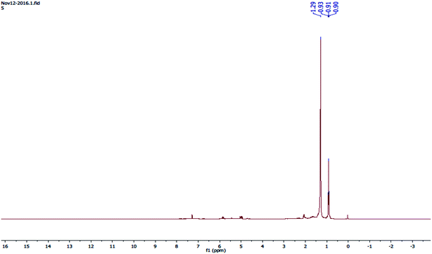
The 1H-NMR spectra (Fig. 10) shows four peaks, and four types of protons were present in the liquid hydrocarbon fuel such as a possible compound: 2-cyclohexyl-2-phenyl-.
 |
| | Fig. 10
1H-NMR spectrum of waste HD-PE plastic catalysed with CuCO3 to obtain liquid hydrocarbon fuel. | |
4. Conclusion
The current study had the definite aim of analyzing and developing the catalytic conversion of waste HD-PE plastic into liquid hydrocarbon fuel and the experiments to do this were successfully carried out during the research. Conversion of waste HD-PE plastic with CuCO3 as the catalyst using a pyrolysis-catalytic technique resulted in various hydrocarbon fractions being found. With the increase of the percentage of the catalyst used, the yield also increased and the yield without the catalyst was less. The liquid hydrocarbon fuel collected had a density of 86 g ml−1. Analyses of liquid hydrocarbon fuel using 2D GCxGC/TOFMS found n-paraffins, olefins, iso-paraffins, cyclic paraffins, aromatics (mono-, di- and poly-aromatics), polar compounds and other hydrocarbons. The petrol engine of a bike was run successfully using the liquid hydrocarbon fuel obtained from the waste HD-PE plastic. The liquid hydrocarbon fuel collected from the waste HD-PE plastic was analyzed using various test methods for petrol/diesel was found to be equivalent to petrol and diesel. Liquid hydrocarbon fuel and waste HD-PE plastics were analyzed using FT-IR and the results showed that every functional group had hydrocarbons. Liquid hydrocarbons and solid residues are very good sources of chemicals/hydrocarbons and this technique will be useful for the petrochemical industries. Liquid hydrocarbon fuel is also highly inflammable and has an ignition capability.
Conflicts of interest
There are no conflicts to declare.
References
-
PlasticsEurope, Plastics-the facts 2016, Analysis of european latest plastics production, demand and waste data, 2016 Search PubMed.
-
PlasticsEurope, Plastics-the facts 2015, Analysis of european latest plastics production, demand and waste data, 2015 Search PubMed.
- European Parliament and the Council of the European Union, Directive 2008/98/EC of the European Parliament and of the council of 19 November 2008 on waste and repealing certain Directives, Official Journal of the European Union, 2008.
-
Technopolis Group, Fraunhofer ISI, Thinkstep and Wuppertal Institute, Regulatory barriers for the circulatory economy: Lessons from ten case studies, Final report, Technopolis Group, 2016 Search PubMed.
-
US EPA, Advancing Sustainable Materials Management: 2014 Fact Sheet, United States Environmental Protection Agency (US EPA), 2016 Search PubMed.
- W. Kaminsky, M. Predel and A. Sadiki, Feedstock recycling of polymers by pyrolysis in a fluidised bed, Polym. Degrad. Stab., 2004, 85, 1045–1050 CrossRef CAS.
-
Plastic Europe, The compelling facts about plastic, Brussels, 2007–2008 Search PubMed.
- J. Shah, M. Rasul and A. Adnan, Catalytic activity of metal impregnated catalysts for degradation of waste polystyrene, J. Ind. Eng. Chem., 2013, 20, 3604–3611 CrossRef.
- Indian industry looks to double plastics use by 2020.
- Y. H. Lin and M. H. Yang, Catalytic conversation of commingled polymer waste into chemicals and fuels over spent FCC commercial catalyst in a fluidized-bed reactor, Appl. Catal., B, 2007, 69, 145–153 CrossRef CAS.
- J. Shah, M. R. Jan, F. Mabood and F. Jabeen, Catalytic pyrolysis of LDPE leads to valuable resource recovery and reduction of waste problems, Energy Convers. Manage., 2010, 51, 2791–2801 CrossRef CAS.
- C. Tang, Y. Wang, Q. Zhou and L. Zheng, Catalytic effect of Al–Zn composite catalyst on the degradation of PVC-containing polymer mixtures into pyrolysis oil, Polym. Degrad. Stab., 2003, 81, 89–98 CrossRef CAS.
- B. Saha, P. Chowdhary and A. K. Ghoshal, Al-MCM-41 catalyzed decomposition of polypropylene and hybrid genetic algorithm for kinetics analysis, Appl. Catal., B, 2008, 83, 265–276 CrossRef CAS.
- M. N. Almustapha and J. M. Andresen, Recovery of valuable chemicals from high density polyethylene (HDPE) polymer: a catalytic approach for plastic waste recycling, Int. J. Environ. Sci. Dev., 2012, 3, 263–267 CrossRef CAS.
- Q. Zhou, Y. Wang, C. Tang and Y. Zhang, Modifications of ZSM-5 zeolites and their applications in catalytic degradation of LDPE, Polym. Degrad. Stab., 2003, 81, 23–30 CrossRef.
- Y. H. Line, M. H. Yanga, T. F. Yehb and M. D. Gerb, Catalytic degradation of high density polyethylene over mesoporous and microporous catalysts in a fluidised-bed reactor, Polym. Degrad. Stab., 2004, 86, 121–128 CrossRef.
- Y. Wang, Q. Huang, Z. Zhou, J. Yang, F. Qi and Y. Pan, Online study on the pyrolysis of polypropylene over the HZSM-5 zeolite with photoionization time-of-flight mass spectrometry, Energy Fuels, 2015, 29, 1090–1098 CrossRef CAS.
- C. L. Laura, S. R. Maria, S. Ulises and B. P. Liliana, Tertiary recycling of low-density polyethylene by catalytic cracking over ZSM-11 and BETA zeolites modified with Zn2+: stability study, Energy Fuels, 2013, 27, 2202–2208 CrossRef.
- M. Sarker, M. M. Rashid and M. S. Rahman, Transforming fuel from municipal waste plastic using nickel silica {Ni (SiO2)} catalyst, Int. J. Chem., Environ. Pharm. Res., 2012, 3, 109–116 CAS.
- M. Liu, K. Z. Jian, J. X. Si and Q. Yao, Catalytic degradation of high-density polyethylene over a clay catalyst compared with other catalysts, Energy Fuels, 2014, 28, 6038–6045 CrossRef CAS.
- Chemical composition of petroleum, http://chemistry.about.com/od/geochemistry/a/Chemical-Composition-Of-Petroleum.htm, accessed 20-09-2016.
-
A. Joshi, Rambir and R. Punia, Conversion of plastic wastes into liquid fuel-a review, Recent Advances in Bioenergy Research, 2014, vol. 3, pp. 444–454 Search PubMed.
- Energy sources, http://www.griet.ac.in/nodes/EC_UNIT_5.pdf, accessed 22-09-2016.
- K. T. Kyaw and C. S. S. Hmwe, Effect of various catalysts on fuel oil pyrolysis process of mixed plastic waste, Int. J. Adv.
Eng. Technol., 2015, 8, 794–802 Search PubMed.
- B. K. Sharma, B. R. Moser, K. E. Vermillion, K. M. Doll and N. Rajagopal, Production, characterization and fuel properties of alternative diesel fuel from pyrolysis of waste plastic grocery bags, Fuel Process. Technol., 2014, 122, 79–90 CrossRef CAS.
- G. Elordi, M. Olazar, G. Lopez, M. Amutio, M. Artetxe, R. Aguado and J. Bilbao, Catalytic pyrolysis of HDPE in continuous mode over zeolite catalyst in a conical spouted bed reactor, J. Anal. Appl. Pyrolysis, 2009, 85, 345–351 CrossRef CAS.
- W. Sriningsih, M. G. Saerodji, W. Trisunaryanti, Triyono, R. Armunanto and L. I. Falah, Fuel production from LDPE plastic waste over natural zeolite supported Ni, Ni-Mo, Co and Co-Mo metals, Procedia Environ. Sci., 2014, 20, 215–224 CrossRef CAS.
- M. Sarker, M. M. Rashid and M. Molla, Abundant high-density polyethylene (HDPE-2) turns into fuel by using of HZSM-5 catalyst, J. Fundam. Renewable Energy Appl., 2011, 1, 1–12 Search PubMed.
- M. Sarker, M. M. Rashid, M. S. Rahman and M. Molla, Environmentally harmful low density waste plastic conversion into kerosene grade fuel, J. Environ. Prot., 2012, 3, 700–708 CrossRef CAS.
- L. Sorum, M. Gronli and J. E. Hustad, Pyrolysis characteristics and kinetics of municipal solid wastes, Fuel, 2001, 80, 1217–1227 CrossRef CAS.
- B. Kunwar, H. N. Cheng, S. R. Chandrashekaran and B. K. Sharma, Plastics to fuel: a review, Renewable Sustainable Energy Rev., 2016, 54, 421–428 CrossRef CAS.
- E. T. Hilal, D. Thomas, R. D. Marko, M. V. G. Kevin and B. M. Guy, Detailed compositional characterization of plastic waste pyrolysis oilby comprehensive two-dimensional gas-chromatography coupled to multiple detectors, J. Chromatogr. A, 2014, 1359, 237–246 CrossRef PubMed.
- J. Huang and G. L. Rempel, Ziegler and Natta catalysts for olefin polymerization: mechanistic insights from metallocene system, Prog. Polym. Sci., 1995, 20, 459–526 CrossRef CAS.
- K. R. Devy, A. N. Mohamad and T. W. Paul, Catalytic pyrolysis of waste plastics using staged catalysis for production of gasoline range hydrocarbons oils, J. Appl. Anal., 2017, 124, 631–637 Search PubMed.
- G. Lopez, M. Artexe, M. Amutio, J. Bilbao and M. Olazar, Thermochemical routes for the valorization of waste polyolefinic plastics produce fuels and chemical: A review, Renewable Sustainable Energy Rev., 2017, 73, 346–368 CrossRef CAS.
- B. Kunwar, B. R. Moser, S. R. Chandrasekaran, N. Rajagopalan and B. K. Sharma, Catalytic thermal depolymerization of low value post-consumer high density polyethylene plastics, Energy, 2016, 111, 884–892 CrossRef CAS.
- J. Shabtai, X. Xiao and W. Zmierczak, Depolymerization-liquefaction of plastics and rubbers. 1. Polyethylene, polypropylene, and polybutadiene, Energy Fuels, 1997, 11, 76–87 CrossRef CAS.
- O. S. Woo, N. Ayala and L. J. Broadbelt, Mechanism interpretation of base-catalyzed depolymerization of polystyrene, Catal. Today, 2000, 55, 161–171 CrossRef CAS.
- W. Sriningsih, M. G. Saerodji, W. Trisunaryanti, Triyono, R. Armunanto and I. I. Falah, Fuel production from LDPE plastic waste over natural zeolite supported Ni, Ni–Mo, Co and Co–Mo metals, Procedia Environ. Sci., 2014, 20, 215–224 CrossRef CAS.
- S. L. Su, A. W. M. Wan, K. C. Chin, O. Rozita, T. C. Cheng and A. C. Howard, Recovery of diesel-like fuel from waste palm oil by pyrolysis using a microwave heated bed of activated carbon, Energy, 2016, 115, 791–799 CrossRef.
- S. L. Su, K. L. Rock, J. Ahmad, T. C. Cheng, N. A. Farid and A. C. Howard, Progress in waste oil to sustainable energy, with emphasis on pyrolysis techniques, Renewable Sustainable Energy Rev., 2016, 50, 741–753 Search PubMed.
- W. A. W. Mahari, N. F. Zainuddin, C. T. Chong, C. L. Lee, W. H. Lam, S. C. Poh and S. S. Lam, Conversion of waste shipping oil into diesel-like oil via microwave-assisted pyrolysis, Int. J. Environ. Sci. Dev., 2017, 5, 5836–5842 Search PubMed.
Footnote |
| † Electronic supplementary information (ESI) available. See DOI: 10.1039/c8se00040a |
|
| This journal is © The Royal Society of Chemistry 2018 |
Click here to see how this site uses Cookies. View our privacy policy here.  *a,
Sudesh
Kumar
a and
Moinuddin
Sarker
b
![[thin space (1/6-em)]](https://www.rsc.org/images/entities/char_2009.gif) 2 and 25.8 million tons of post-consumer plastic waste was produced in 2014. Thus, the treatment of post-consumer plastic waste is an important and increasing challenge. The seven types of common plastics are given in brackets with the percentage of European plastic demand for each polymer in 2014 (Plastics Europe, 2015): poly(propylene) [PP, (C3H6)n, 19.2%], low-density poly(ethylene) [(C2H4)n, 17.2%], high-density poly(ethylene) [HD-PE, (C2H4)n, 12.1%], poly(vinylchloride) [(C2H3Cl)n, 10.3%], polyurethane (C17H16N2O4, 7.5%), poly(ethylene terephthalate) [PET, (C108O4)n, 7.0%], and poly(styrene) [PS, (C8H8)n, 7.0%]. The European Union (EU) recommends a waste treatment hierarchy with the subsequent order of preference:3
2 and 25.8 million tons of post-consumer plastic waste was produced in 2014. Thus, the treatment of post-consumer plastic waste is an important and increasing challenge. The seven types of common plastics are given in brackets with the percentage of European plastic demand for each polymer in 2014 (Plastics Europe, 2015): poly(propylene) [PP, (C3H6)n, 19.2%], low-density poly(ethylene) [(C2H4)n, 17.2%], high-density poly(ethylene) [HD-PE, (C2H4)n, 12.1%], poly(vinylchloride) [(C2H3Cl)n, 10.3%], polyurethane (C17H16N2O4, 7.5%), poly(ethylene terephthalate) [PET, (C108O4)n, 7.0%], and poly(styrene) [PS, (C8H8)n, 7.0%]. The European Union (EU) recommends a waste treatment hierarchy with the subsequent order of preference:3


![[thin space (1/6-em)]](https://www.rsc.org/images/entities/char_2009.gif) :
:![[thin space (1/6-em)]](https://www.rsc.org/images/entities/char_2009.gif) 150. The GCxGC oven program was: 70 °C held for 1.0 min, 10 °C min−1 to 280 °C, held for 5 min, and the temperature of the primary oven was offset by 35 °C and the secondary oven temperature was offset by 10 °C, with a total run time of 27.0 min. A modulation unit was located between both of the columns and it was the most important component of the 2D chromatography. The modulator occasionally sampled runoff from the initial column then automatically injected it into the next column. The 2D splitting was finished as soon as the next modulation started. All the chemicals were separated by two special columns, modulation period 4 s, hot pulse 0.9 s, cold pulse 1.1 s. The setup of the two columns ensured that the all 2D separation was finished before the one-dimensional (1D) analysis, the source temperature was 200 °C, the electron ionization was 70 eV, the mass range was 35 to 600 μ. The MS permitted accurate identification to be made for the whole of the chromatogram. Quadrupole mass spectrometers working in full scan mode were too slow to properly sample a GC × GC peak. However, TOFMS that work with spectral acquisition rates of 500 Hz were well suited for used with GC × GC. Nuclear magnetic resonance (NMR) spectroscopy with a 400 MHz instrument (Bruker) was used to analyze the correlation between carbon and proton atoms in liquid hydrocarbon fuel. Elemental analysis of liquid hydrocarbons was performed to determine the contents of carbon (C), hydrogen (H) and nitrogen (N) using a 24000 Series-II CHNS/O elemental analyzer (PerkinElmer). The functional groups of the liquid hydrocarbons and the waste HD-PE were determined using Fourier-transform infrared (FT-IR) spectrometry with an Alpha-T spectrometry (Bruker).
150. The GCxGC oven program was: 70 °C held for 1.0 min, 10 °C min−1 to 280 °C, held for 5 min, and the temperature of the primary oven was offset by 35 °C and the secondary oven temperature was offset by 10 °C, with a total run time of 27.0 min. A modulation unit was located between both of the columns and it was the most important component of the 2D chromatography. The modulator occasionally sampled runoff from the initial column then automatically injected it into the next column. The 2D splitting was finished as soon as the next modulation started. All the chemicals were separated by two special columns, modulation period 4 s, hot pulse 0.9 s, cold pulse 1.1 s. The setup of the two columns ensured that the all 2D separation was finished before the one-dimensional (1D) analysis, the source temperature was 200 °C, the electron ionization was 70 eV, the mass range was 35 to 600 μ. The MS permitted accurate identification to be made for the whole of the chromatogram. Quadrupole mass spectrometers working in full scan mode were too slow to properly sample a GC × GC peak. However, TOFMS that work with spectral acquisition rates of 500 Hz were well suited for used with GC × GC. Nuclear magnetic resonance (NMR) spectroscopy with a 400 MHz instrument (Bruker) was used to analyze the correlation between carbon and proton atoms in liquid hydrocarbon fuel. Elemental analysis of liquid hydrocarbons was performed to determine the contents of carbon (C), hydrogen (H) and nitrogen (N) using a 24000 Series-II CHNS/O elemental analyzer (PerkinElmer). The functional groups of the liquid hydrocarbons and the waste HD-PE were determined using Fourier-transform infrared (FT-IR) spectrometry with an Alpha-T spectrometry (Bruker).


![[double bond, length as m-dash]](https://www.rsc.org/images/entities/char_e001.gif) C stretch functional group of wave frequency 1641.51, methylene C–H bend functional group of wave frequency 1463.88, vinylidene C–H in plane bending functional group of wave frequency 1377.48, vinylidene C–H out of plane bending functional group of wave frequency 991.76, trans C–H out-of-plane bending functional group of wave frequency 965.28 cm−1, aromatic C–H out of plane bending functional group of wave frequency 908.91, 1,3 disubstitution (meta) functional group of wave frequency 888.17, 1,3 disubstitution (ortho) functional group of wave frequency 721.48 cm−1, and alkyne C–H bend functional group of wave frequency 632.59 (see Fig. 8).
C stretch functional group of wave frequency 1641.51, methylene C–H bend functional group of wave frequency 1463.88, vinylidene C–H in plane bending functional group of wave frequency 1377.48, vinylidene C–H out of plane bending functional group of wave frequency 991.76, trans C–H out-of-plane bending functional group of wave frequency 965.28 cm−1, aromatic C–H out of plane bending functional group of wave frequency 908.91, 1,3 disubstitution (meta) functional group of wave frequency 888.17, 1,3 disubstitution (ortho) functional group of wave frequency 721.48 cm−1, and alkyne C–H bend functional group of wave frequency 632.59 (see Fig. 8).


