Facile fabrication of a 3D network composed of N-doped carbon-coated core–shell metal oxides/phosphides for highly efficient water splitting†
Qi
Hu
,
Xiufang
Liu
,
Chaoyun
Tang
,
Liangdong
Fan
 ,
Xiaoyan
Chai
,
Qianling
Zhang
,
Jianhong
Liu
and
Chuanxin
He
,
Xiaoyan
Chai
,
Qianling
Zhang
,
Jianhong
Liu
and
Chuanxin
He
 *
*
College of Chemistry Environmental Engineering, Shenzhen University, Shenzhen, Guangdong 518060, People's Republic of China. E-mail: Hecx@szu.edu.cn
First published on 13th March 2018
Abstract
Development of robust, bifunctional, and non-precious catalysts for oxygen and hydrogen evolution reactions (OER and HER) is a prerequisite to realizing the overall splitting of water. This, however, remains a great challenge. In this context, we fabricated a novel three-dimensional (3D) network comprising N-doped carbon-coated core–shell NiFeOx@NiFe–P (denoted as NC–NiFeOx@NiFe–P) by two-pot high-temperature phosphorization and surface oxidation of a NiFe-Prussian blue analogue/polyvinylpyrrolidone (denoted as NiFe–PBAs/PVP) hybrid precursor. The as-synthesized NC–NiFeOx@NiFe–P catalyst demonstrated exceptional performance for both OER and HER, offering a current density of 10 mA cm−2 (a metric related to solar fuel) at small overpotentials of 285 mV for the OER and 237 mV for the HER in 1 M KOH, respectively. As expected, a NC–NiFeOx@NiFe–P based alkaline electrolyzer with durability of 20 h was manufactured to achieve 10 mA cm−2 at a voltage of 1.59 V, outperforming most non-precious metal-based electrolyzers. The exceptional performance could be attributed to the unique 3D network composed of core–shell NiFeOx@NiFe–P and highly conductive N-doped carbon (NC), which provided a large amount of highly active sites for both OER and HER and favored fast electron transport during electrocatalytic processes.
Introduction
As a clean and highly efficient energy, hydrogen has been widely recognized as a desirable candidate instead of fossil fuels to slow down the increasingly severe energy crisis and environmental pollution. The electrochemical splitting of water is an effective and easy way to produce hydrogen.1 However, the anodic oxygen evolution reaction (OER) and cathodic hydrogen evolution reaction (HER) in such water splitting often need a large overpotential to achieve preferable reaction rates.2 To address these issues, excellent Pt- and Ru/Ir-based catalysts were developed for the HER and OER, respectively.3 Unfortunately, the scarcity and high-cost of those precious metals greatly hinder their actual application. Besides, because of the extraordinarily large overpotential required for the OER and vulnerability of most non-precious OER catalysts in acidic media, most of the water splitting reactions were performed in alkaline media.4 However, non-precious metal-based catalysts (i.e. MoS2 and MoC2) for the HER,5 which perform well in acidic media, often suffer from low-activity in alkali electrolytes. Therefore, development of non-precious metal-based electrocatalysts qualified for both OER and HER in alkali electrolytes is highly imperative for overall water splitting. This, however, still remains a challenging work.Due to the advantages of high-activity and low-cost, non-precious transition metal phosphides (TMPs) have emerged as a new family of promising OER and/or HER catalysts. For example, nickel, cobalt and iron phosphides exhibited excellent performance for the HER with low overpotentials in acid or alkali electrolytes.6 Afterwards, surface oxidized NiP2 was found to possess significantly improved OER activity due to the core–shell structure of NiP2/NiOx.7 Improved performance was also found for oxidized CoP2 and CoMnP catalysts.8 Despite great achievements made on the use of these TMPs as catalysts for the OER, they still need a large overpotential (>300 mV) to reach a current density of 10 mA cm−2. Moreover, previous reports indicated that coordination of different metal sites could improve the electroactivity by improving the adsorption of electrochemical intermediates.9 In this context, effective combination of different metal phosphides may be a promising way to further improve the electrocatalytic performance. Recently, a N, P-co-doped three-dimensional (3D) porous network carbon nanomaterial has shown great potential for both OER and HER.10 Therefore, in light of the possible electrocatalytic synergy, incorporation of surface oxidized binary TMPs and N-doped 3D network carbon may further enhance the activity for the OER and HER, and the new catalyst will be highly suitable for water splitting. Unfortunately, such special incorporation is still scarce.
Prussian blue analogues (PBAs), denoted as M3II[MIII(CN)6]2·nH2O, are a family of well-organized metal–organic frameworks (MOFs), which contain transition metals (i.e., Co, Ni, Fe) as metallic nodes and CN− as linkers.11 By virtue of the variety in their chemical composition and microstructure, PBAs have been desirable precursors to construct non-precious metal-based electrocatalysts with elaborate architecture.12 Inspired by the above results, herein, an easy yet valid strategy was adopted to fabricate a 3D network comprising N-doped carbon-coated core–shell NiFeOx@NiFe–P (denoted as NC–NiFeOx@NiFe–P) through two-step high-temperature phosphorization and surface oxidation of a NiFe–PBAs/PVP hybrid precursor. Intriguingly, we found that the outer PVP layer in the precursor could not only transform to N-doped carbon but also prevent the aggregation of the resulting mixed Ni/Fe phosphide (NiFe–P) nanoparticles (NPs) during high-temperature phosphorization, thus promoting generation of the well-ordered 3D network structure. Consequently, the as-synthesized NC–NiFeOx@NiFe–P catalyst displayed high activity for both OER and HER in 1 M KOH. Based on electrocatalytic results, the excellent performance could be attributed to the following three reasons: (1) the well-organized 3D network with high conductivity giving rise to exposure of more active sites and facilitating the electron transfer during the OER and HER; (2) the highly active centers on both mixed Ni and Fe oxide (NiFeOx) shell and N-doped carbon; (3) the NiFe–P core providing sites to adsorb the H atom during the HER6b and facilitating the proton transfer during the OER.13 Notably, an alkaline electrolyzer that achieved 10 mA cm−2 at a voltage of 1.59 V with durability of 20 h was successfully achieved by employing the NC–NiFeOx@NiFe–P catalyst as both the cathodic and anodic electrocatalysts, providing a promising candidate for water splitting.
Experimental section
The synthesis of electrocatalysts
The NiFe–PBA/PVP hybrid composites were synthesized by a modified coprecipitation method. Solution A: 1.4928 g Ni(CH3COOH)2·4H2O and 12 g PVP were dissolved in 100 ml alcohol to form a mixed solution. Solution B: 1.3270 g K3[Fe(CN)6] was dissolved in 20 ml deionized water to form another solution. Then solution B was added dropwise into solution A under intense stirring at room temperature. The resulting aqueous solution was aged for 2 h, and the precipitate was then collected by centrifugation without washing. The precipitate was dried at 80 °C for 24 h and is denoted as NiFe–PBA/PVP. After that, NaH2PO2·H2O was selected as the phosphorus source and fully mixed with the above NiFe–PBA/PVP at the mass ratio of 1![[thin space (1/6-em)]](https://www.rsc.org/images/entities/char_2009.gif) :
:![[thin space (1/6-em)]](https://www.rsc.org/images/entities/char_2009.gif) 8 by grinding. Then, the above mixture was calcined at 400 °C and 700 °C for 2 h, respectively, under an Ar atmosphere. Finally, the calcined product (0.2 g) was washed in 100 ml deionized water at 50 °C for 24 h under stirring to remove the sodium phosphate derived from NaH2PO2·H2O. At the same time, mixed Ni/Fe layers were formed on the surface of NiFe–P NPs due to the oxidation by air, and the final product is denoted as NC–NiFeOx@NiFe–P. Besides, to synthesize NC–NiFe–P without the NiFeOx shell, the above calcined product (0.2 g) was also washed in 100 ml deoxygenized water at 50 °C under an Ar atmosphere for 24 h.
8 by grinding. Then, the above mixture was calcined at 400 °C and 700 °C for 2 h, respectively, under an Ar atmosphere. Finally, the calcined product (0.2 g) was washed in 100 ml deionized water at 50 °C for 24 h under stirring to remove the sodium phosphate derived from NaH2PO2·H2O. At the same time, mixed Ni/Fe layers were formed on the surface of NiFe–P NPs due to the oxidation by air, and the final product is denoted as NC–NiFeOx@NiFe–P. Besides, to synthesize NC–NiFe–P without the NiFeOx shell, the above calcined product (0.2 g) was also washed in 100 ml deoxygenized water at 50 °C under an Ar atmosphere for 24 h.
For comparison, 0.2 g of the NC–NiFeOx@NiFe–P catalyst was dispersed in 80 ml deionized water. The resulting suspension was then transferred into a 100 ml Teflon-lined stainless-steel autoclave, which was heated at 100 °C for 12 h and then cooled to ambient temperature naturally. Finally, the product was collected by centrifugation, and is denoted as NC–NiFeOx@NiFe–P-100. The NiFe–PBA precursor and resulting NiFeOx@NiFe–P catalyst were synthesized through the same process as that for the NiFe–PBA/PVP precursor and NC–NiFeOx@NiFe–P catalyst but without the addition of PVP, respectively. The NC–NiFe was synthesized in a similar manner to that for NiFeOx@NiFe–P without addition of NaH2PO2·H2O during calcination.
Characterization
The X-ray diffraction (XRD) data of various samples were recorded using a D8 ADVANCE diffractometer with a graphite-filtered CuKα source (λ = 0.15418 nm) over a 2θ range of 5–70°. Field emission scanning electron microscopy (FESEM) was performed using a JEOL JSM-7800F. Transmission electron microscopy (TEM) and high-resolution TEM (HRTEM) were recorded using a JEOL 2100 electron microscope at an acceleration voltage of 200 kV. HAADF-STEM-EDS images were collected on a JEM-2100F instrument with an EDS system. Raman spectroscopy was performed using a microscopic confocal Raman spectrometer (Jobin Yvon Horiba HR800) at room temperature. Elemental contents were determined using a Vario EI elemental analyzer. X-ray photoelectron spectroscopy (XPS) data were collected on a Thermo VG ESCALAB 250 X-ray photoelectron spectrometer with AlKα X-ray radiation. Binding energies of different elements were corrected based on the graphitic C 1s peak at 284.6 eV.Electrochemical characterization
The electrochemical performance of as-synthesized catalysts towards the OER and HER was studied on an electrochemical workstation (CHI 760 E) in 1 M KOH electrolyte. All electrochemical measurements were conducted on a three-electrode system with carbon electrodes as counter electrodes, saturated calomel as reference electrodes and catalyst modified glassy carbon electrodes (geometric surface area: 0.07 cm2) as working electrodes. The catalyst inks were prepared by dispersing as-synthesized catalysts and Nafion in absolute ethanol under 0.5 h sonication. Then the catalyst inks were loaded on glassy carbon electrodes with catalyst loading of 0.2 mg cm−2. Electrochemical impedance spectroscopy (EIS) was carried out from 1 MHz to 1 Hz at a potential of 1.53 V for the OER and −0.2 V for the HER, respectively, in 1 M KOH solution. Cyclic voltammetry (CV) was performed on the NC–NiFeOx@NiFe–P catalyst at a scan rate of 100 mV s−1 for 2000 cycles in 1 M KOH to study the cycling durability for the OER. As for the two-electrode system in the overall splitting of water, the as-synthesized catalysts (i.e. NiFeOx@NiFe–P, NC–NiFe, and NC–NiFeOx@NiFe–P) were dispersed in the mixed solution of ethanol and Nafion, the resulting solution was dropped on nickel foam (1 × 1 cm) with catalyst loading of 1 mg cm−2. The stability of the as-synthesized catalysts for overall splitting of water was investigated using the time-dependent current density curves in 1 M KOH.Electrical double layer capacitance measurement
It is well known that the electrochemically active surface area (ECSA) can be measured by double layer capacitance (Cdl). Cdl was determined from the cyclic voltammograms (CVs) of various catalysts at different scan rates (0.04, 0.06, 0.08, 0.10, 0.12 and 0.14 V s−1) in a non-faradaic potential range of 1.27 to 1.33 V vs. RHE. Afterwards, the corresponding capacitive current was plotted at 1.3 V at different scan rates of CV, and the slope of the fitted line was twice Cdl. Finally, the ECSA can be calculated ashere, the common specific capacitance Cs = 0.04 mF cm−2 was applied in our calculation.
Results and discussion
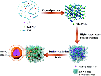
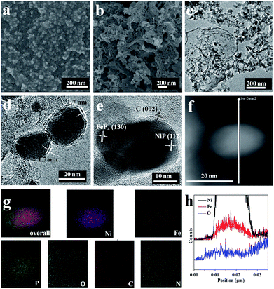
The fabrication process for the 3D network comprising N-doped carbon-coated core–shell NiFeOx@NiFe–P (denoted as NC–NiFeOx@NiFe–P) involves three steps (Fig. 1). First, the NiFe–PBA/PVP hybrid precursors were synthesized through a facile coprecipitation method (upper right panel in Fig. 1). After high-temperature phosphorization, the metal ions (i.e. Ni2+ and Fe3+) transformed to correspondingly mixed metal phosphide (i.e. NiP, NiP2 and FeP4) NPs (denoted as NiFe–P). In this process, CN− and PVP were employed as carbon and nitrogen sources to in situ form N-doped carbon, thus connecting NiFe–P NPs to create a 3D network structure (lower right panel in Fig. 1). Finally, the NiFe–P NPs were surface oxidized in air to form core–shell NiFeOx@NiFe–P nanoparticles (lower left panel in Fig. 1). The XRD pattern of the NiFe–PBA/PVP precursor shows a series of characteristic diffractions related to (200), (220), (400), (422), (440), (660) and (620) planes for PBAs (JCPDS no. 20-0915) (Fig. S1†). After high-temperature phosphorization and surface oxidation, intense diffractions indexed to NiP (JCPDS no. 18-0882), NiP2 (JCPDS no. 13-0213) and FeP4 (JCPDS no. 32-0471) can be observed on the NC-NiFeOx@NiFe–P sample, implying the formation of mixed Ni and Fe phosphides (NiFe–P) (Fig. S2†). Interestingly, no diffractions related to Ni/Fe oxides were observed, implying that the Ni/Fe oxides are in the amorphous form. Besides, as shown in Fig. S3,† the NC–NiFe catalyst (which served as the control sample; see the Experimental section) exhibits an intense (111) diffraction at 43.7° and a weak (200) one at 53.1°, suggesting the generation of cubic Ni0.36Fe0.64 alloys (JCPDS no. 47-1405).The morphology and microstructure of NiFe–PBA/PVP before high-temperature phosphorization as well as the resulting phosphorized and oxidized product (NC–NiFeOx@NiFe–P) was studied by FESEM and TEM (Fig. 2). In the FESEM image of NiFe–PBA/PVP, a large number of NiFe–PBA NPs in the size of around 20 nm with PVP overlayers were found (Fig. 2a), further confirming the successful synthesis of NiFe–PBA/PVP hybrid composites. After high-temperature phosphorization and surface oxidation, a 3D network structure was observed, as shown in Fig. 2b. The corresponding TEM image in Fig. 2c exhibits numerous black NPs in the size of ∼25 nm embedded in the bright 3D network carbon. After increasing the magnification times, overlayers of carbon at a thickness of 1.7 nm can also be found on the surface of NPs (Fig. 2d). Moreover, the clear and continuous lattice fringes throughout the NPs in distances of 0.26, 0.22 and 0.34 nm are well in agreement with the d spacing of the (112) plane of NiP, (130) plane of FeP4 and (200) plane of graphitic carbon (Fig. 2e), respectively, indicating the formation of mixed NiFe–P and graphitic carbon overlays. The situation is well consistent with the XRD result. The elemental mapping of NC–NiFeOx@NiFe–P based on HADDF-STEM-EDS indicates the uniform distribution of Ni, Fe, P, O, C and N elements (Fig. 2g). It should be noted that the O element is more likely to be distributed around the NiFe–P (Ni, Fe and P elements) NPs to form a surface mixed Ni and Fe oxide (NiFeOx) shell. Moreover, the distribution of O element in the EDS line spectrum is seemingly at the edge of the NiFe–P NPs (Ni, Fe elements) (Fig. 2h), rather than in the middle, further verifying the formation of the surface NiFeOx shell. It is well known that the metal phosphides could be oxidized by air even at room temperature.14 Clearly, the surface NiFeOx shell is in situ generated by the oxidation in air during the washing process at 50 °C. Besides, the Raman spectrum of the NC–NiFeOx@NiFe–P catalyst indicates two Raman peaks at 1345 and 1580 cm−1 (Fig. S4†), which can be assigned to the D and G bands, respectively. The relative high intensity ratio of the ID/IG band (∼1.71) (area ratio) indicates the formation of defects, which may be related to N atom doping into carbon.15
For comparison, FESEM was also conducted over the NiFe–PBA sample without addition of PVP and the corresponding high-temperature phosphorization and surface oxidation product (NiFeOx@NiFe–P). The FESEM image of NiFe–PBA shows a uniformly distributed morphology similar to NiFe–PBA/PVP except for the PVP overlayers (Fig. S5a†). However, after high-temperature phosphorization and surface oxidation, the NiFeOx@NiFe–P sample displays a poorly distributed morphology without the 3D network structure (Fig. S5b†), which is distinctly different from that of NC–NiFeOx@NiFe–P. The huge NPs without the 3D network structure can also be observed in the TEM image of NiFeOx@NiFe–P (Fig. S6†). On the other hand, it is reported that the PVP transformed to N-doped carbon through thermal decomposition.16 Moreover, as shown in Table S1,† the content of C and N elements in NC–NiFeOx@NiFe–P is much higher than those in NiFeOx@NiFe–P, indicating the presence of a much larger amount of N-doped carbon in NC–NiFeOx@NiFe–P. The result further confirms that the pyrolysis of PVP in the NiFe–PBA/PVP precursors could form graphitic N-doped carbon. Thus, in the present system, it is evident that the PVP is transformed to a 3D N-doped carbon network during high-temperature phosphorization, thus prohibiting the agglomeration of NiFe–P NPs. Based on the above results, it can be speculated that the generation of the 3D network structure is related to the following three aspects. First, the Ni and Fe metal ions react with PH3 gas derived from the pyrolysis of NaH2PO2·H2O to form the mixture of NiFe–P. Second, the CN− linkers on PBAs play the role of both carbon and nitrogen source to form N-doped graphene layers encapsulating metal phosphides. Finally, the large amount of PVP overlayers can transform to N-doped carbon, thus linking metal phosphides to generate the 3D network structure.
XPS was performed on NiFeOx@NiFe–P and NC–NiFeOx@NiFe–P catalysts to study their surface electronic states (Fig. 3). As shown in Fig. 3a, the survey XPS of NC–NiFeOx@NiFe–P reveals the existence of Ni, Fe, P, O, C and N elements.
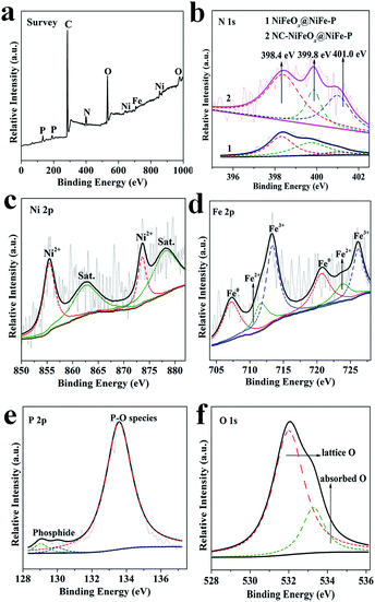 | ||
| Fig. 3 XPS survey spectrum of (a) NC–NiFeOx@NiFe–P; (b) N 1s for NiFeOx@NiFe–P and NC–NiFeOx@NiFe–P; (c) Ni 2p, (d) Fe 2p, (e) P 2p, (f) O 1s for NC–NiFeOx@NiFe–P. | ||
The high-resolution N 1s spectra of NiFeOx@NiFe–P and NC–NiFeOx@NiFe–P reveal the presence of three different N species, which are pyridinic-N (398.4 eV), pyrrolic-N (399.6 eV) and metallic-N (400.9 eV) (Fig. 3b).10b,17,18 The percentage of pyridinic-N on the NC–NiFeOx@NiFe–P catalyst is 53.32%, which is 1.1-fold of that on NiFeOx@NiFe–P (47.36%). Notably, the pyridinic-N-doped carbon atoms show high activity for the OER and HER.19 The XPS spectrum of Ni 2p on NC–NiFeOx@NiFe–P displays peaks at 855.5 and 873.6 eV for Ni2+ (Fig. 3c),20 suggesting the presence of surface oxidized Ni species. The XPS spectrum of Fe 2p shows the peaks for Fe0 (707.3, 720.7 eV), Fe2+ (711.7, 724.0 eV) and Fe3+ (713.3, 726.2 eV) (Fig. 3d),21 indicating the generation of surface oxidized Fe species. The XPS region of P 2p reveals the presence of two different P species: phosphide (129.1, 130.1 eV) and phosphate (133.6 eV) (Fig. 3e).22 Notably, no obvious peak assigned to the P element (132.7 eV)23 in P-doped carbon can be observed, signifying that only a small amount of P element is doped in carbon. Furthermore, the intense signal for the O 1s spectrum can be deconvoluted to two O species: lattice O (532.0 eV), adsorbed O (533.3 eV) (Fig. 3f). To further confirm the formation of core–shell NiFeOx@NiFe–P, the XPS spectra of Ni, Fe, P and O elements for the NC–NiFeOx@NiFe–P sample after Ar ion etching were also collected. As shown in Fig. S7,† after Ar ion etching of 30 or 60 s, the peaks for oxidized Ni2+, Fe2+, Fe3+ and phosphate species are significantly weakened, and, inversely, intense peaks for metallic Ni0, Fe0, and phosphide species are observed on NC–NiFeOx@NiFe–P. These results indicate that these oxidized species only exist on the surface of NiFe–P NPs to form a NiFeOx shell. The situation is well in agreement with the EDS mapping and line scan results.
The OER activities of the as-synthesized NC–NiFeOx@NiFe–P and commercial RuO2 (Alfa Aesar) catalysts with the same loading of 0.2 mg cm−2 were evaluated in 1 M KOH and are shown in Fig. 4. It can be found that the NC–NiFeOx@NiFe–P catalyst shows superior inherent OER activity with lower onset potential (1.46 V) and higher current density (j) at each overpotential compared with other catalysts (Fig. 4a). As expected, the overpotential (η) to achieve a j of 10 mA cm−2 for the NC–NiFeOx@NiFe–P catalyst is very small (285 mV), which is much smaller than that of NC–NiFe (360 mV) and commercial RuO2 (370 mV) (Table 1). Notably, the η of NC–NiFeOx@NiFe–P is also lower than the values of other previous reports for metal phosphides and in the range of leading non-precious metal-based OER catalysts (Table S2†). However, without the 3D N-doped network carbon, a very high η (477 mV) is needed to achieve a j of 10 mA cm−2 for NiFeOx@NiFe–P, indicating the important role of the 3D carbon in the OER. As shown in Fig. 4b, the Tafel slopes of catalysts increase in the order: NC–NiFeOx@NiFe–P (48 mV dec−1) < NiFeOx@NiFe–P < NC–NiFe < RuO2 (105 mV dec−1), further verifying the high activity of NC–NiFeOx@NiFe–P for the OER. In addition, electrochemical impedance spectroscopy (EIS) analysis was also conducted over different catalysts at a potential of 1.53 V (Fig. 4c). The Nyquist plots of all the three samples reveal two time-constants. As reported well in the literature, the small constant at high frequency belongs to the series resistance, and the other big one at low frequency is related to the charge-transfer resistance (Rct) during electrocatalytic processes.24 Clearly, the NC–NiFeOx@NiFe–P catalyst displays the lowest Rct value, which is in line with its highest OER activity. Moreover, in the absence of the 3D network carbon, a very high Rct value is observed for the NiFeOx@NiFe–P catalyst, suggesting that the highly conductive 3D N-doped network carbon can greatly promote the charge transfer during the OER. Besides, the NC–NiFeOx@NiFe–P catalyst exhibits great stability for the OER with nearly negligible deactivation in 1 M KOH after 2000 cycles or 20 h continuous operation (Fig. 4d and S8†). The stability may be attributed to the 3D carbon stabilization on NiFe–P NPs. It can be concluded that the NC–NiFeOx@NiFe–P catalyst displays robust OER performance with excellent activity, conductivity and stability.
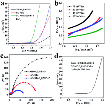 | ||
| Fig. 4 (a) Steady-state OER polarization curves, (b) Tafel plots and (c) EIS of different catalysts; (d) OER polarization curves of NC–NiFeOx@NiFe–P before and after the cycling test for 2000 times. | ||
| Catalyst | OER | C dl (mF cm−2) | ECSA (cm2) | HER | ||
|---|---|---|---|---|---|---|
| η (mV) at 10 mA cm−2 | Tafel slope (mV dec−1) | η (mV) at 10 mA cm−2 | Tafel slope (mV dec−1) | |||
| a η: overpotential, Cdl: double-layer capacitance, ECSA: electrochemically active surface area. | ||||||
| NiFeOx@NiFe–P | 477 | 75 | 2.03 | 50.8 | 407 | 110.4 |
| NC–NiFe | 360 | 89 | 4.14 | 103.5 | 375 | 90.0 |
| NC–NiFeOx@NiFe–P | 285 | 48 | 6.01 | 150.0 | 237 | 65.0 |
To further understand the exceptional performance of the NC–NiFeOx@NiFe–P catalyst, the electrochemically active surface area (ECSA) of different catalysts was assessed in terms of double-layer capacitance (Cdl) (Fig. S9† and 5a). The ECSAs of different catalysts are listed in Table 1. One can see that the ECSA of NC–NiFeOx@NiFe–P is markedly larger than that of NC–NiFe (control sample). This can be attributed to the core–shell structure of NiFeOx@NiFe–P, which affords more active sites.25 Moreover, a very small ECSA value is observed for the NiFeOx@NiFe–P sample without the 3D network carbon, implying the presence of active sites on the 3D carbon. Usually, the catalytic activity of electrocatalysts is essentially associated with their ECSAs.26 Correspondingly, the higher ECSA of the NC–NiFeOx@NiFe–P catalyst compared with other catalysts results in higher OER activity. Furthermore, the ECSA of each catalyst is also used to calculate current density per ECSA (jECSA), and the corresponding polarization curves are shown in Fig. 5b. It can be found that the NC–NiFeOx@NiFe–P catalyst exhibits higher jECSA than the other two catalysts across the whole potential window, indicating the higher activity per active area. On the basis of the above XPS results, there is a large amount of positively charged species including metal oxides (Ni2+, Fe2+ and Fe3+) and pyridinic-N-doped carbon atoms on the NC–NiFeOx@NiFe–P catalyst. It is widely accepted that positively charged species can easily interact with OH−, thus facilitating the withdrawal of electrons from it and promoting the OER in the alkaline electrolyte.27 Therefore, the exceptional activity of NC–NiFeOx@NiFe–P results from the ample active sites with positive charge on both NiFeOx shell and 3D N-doped network carbon.
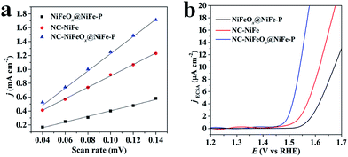 | ||
| Fig. 5 (a) Plots of the current density against scan rates and (b) OER polarization curves standardized by ECSA for NiFeOx@NiFe–P, NC–NiFe and NC–NiFeOx@NiFe–P. | ||
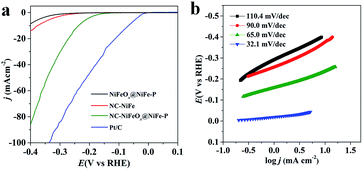
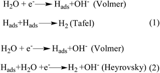
The catalytic performance of the as-synthesized catalysts and commercial Pt/C (Alfa Aesar) catalysts towards the hydrogen evolution reaction (HER) was also evaluated in 1 M KOH. As shown in Fig. 6a, NC–NiFeOx@NiFe–P displays a small overpotential (η) (237 mV) to achieve a j of 10 mA cm−2, whereas NiFeOx@NiFe–P and NC–NiFe require a large η of 407 and 375 mV to achieve a j of 10 mA cm−2 (Table 1), indicating the higher activity of NC–NiFeOx@NiFe–P for the HER. Notably, the excellent performance of NC–NiFeOx@NiFe–P is also superior to that of other non-precious metal-based HER catalysts in alkaline electrolytes (Table S3†). Moreover, NC–NiFeOx@NiFe–P exhibits a significantly lower Tafel slope of 65.0 mV dec−1 than NiFeOx@NiFe–P (110.4 mV dec−1) and NC–NiFe (90.0 mV dec−1) (Fig. 6b), further revealing the higher activity of NC–NiFeOx@NiFe–P for the HER. Generally, the HER under alkaline conditions follows the Volmer–Heyrovsky or Volmer–Tafel process.28 As shown in Fig. 7, both processes involve the adsorption of a H2O molecule, the splitting of adsorbed H2O to adsorbed OH− and H atoms, desorption of OH− to recover the surface, and the formation of H2 from adsorbed H atoms. As reported previously, the TMPs have a strong affinity to H atoms,6c,29 and the metal oxides and pyridinic-N-doped carbon with strong electrostatic affinity can attach to the OH− derived from the decomposition of H2O.30 Correspondingly, in our composite catalysts, the OH− produced by H2O decomposition will preferentially be adsorbed on the surface of NiFeOx and 3D pyridinic-N-doped carbon, and then the H atom will move to adjacent NiFe–P for recombination to produce H2, thus accomplishing the Volmer process and synergic effect. On the basis of the greatly improved ECSA and HER performance caused by the NiFeOx and pyridinic-N-doped network carbon, the exceptional performance of NC–NiFeOx@NiFe–P can be attributed to the synergistic effect between the NiFeOx shell, NiFe–P core and N-doped network carbon. Similar catalytic synergy for the HER was also found in Ni/NiO and Li+–Ni(OH)2–Pt nanocomposites.30a,31 To further confirm the catalytic synergy by experimental means, we further oxidized the NC–NiFeOx@NiFe–P catalysts at 100 °C for 24 h to form a thicker Ni/Fe oxide (NiFeOx) shell, and the new catalysts are denoted as NC–NiFeOx@NiFe–P-100. Then the HER activity of NC–NiFeOx@NiFe–P-100 was evaluated in 1 M KOH. As shown in Fig. S11a,† the NC–NiFeOx@NiFe–P-100 catalyst displays an overpotential of 297 mV at a current density of 10 mA cm−2, which is much larger than that of NC–NiFeOx@NiFe–P (237 mV). This suggests that the thicker NiFeOx shell could hinder the contact of active hydrogen atoms with the Ni/Fe phosphide (NiFe–P) core. In other words, the adsorption and recombination of active hydrogen atoms should happen on the NiFe–P core of NC–NiFeOx@NiFe–P. Moreover, NC–NiFe–P without the NiFeOx shell displays an overpotential of 315 mV at a current density of 10 mA cm−2 for the HER (Fig. S12†), which is much larger than that of NC–NiFeOx@NiFe–P (237 mV). This result implies that the water dissociation should happen on the NiFeOx shell. On the basis of the above results, it is clear that the HER process in NC–NiFeOx@NiFe–P catalysts should follow a catalytic synergy. Besides, the NC–NiFeOx@NiFe–P catalyst exhibits excellent stability for the HER with nearly negligible deactivation after 20 h continuous operation (Fig. S13†), further confirming the 3D carbon stabilization on NiFe–P NPs.
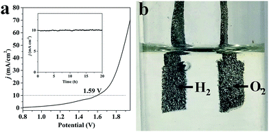
Because of the excellent performance for both OER and HER, we constructed an electrolyzer with 1 M KOH as media through applying NC–NiFeOx@NiFe–P as both a water oxidation and reduction catalyst. As shown in Fig. 8a, the voltage to reach a j of 10 mA cm−2 is 1.59 V, which is lower than that of most non-precious metal-based electrolyzers (Table S4†). Meanwhile, evident bubbles for hydrogen and oxygen are shown on Ni foam at 1.59 V, indicative of the occurrence of overall water splitting (Fig. 8b). In sharp contrast, large voltages are required for NiFeOx@NiFe–P (1.81 V) and NC–NiFe (1.75 V) catalysts to achieve a j of 10 mA cm−2, further confirming the high activity of NC–NiFeOx@NiFe–P for overall water splitting (Fig. S12†). As a key parameter to evaluate the performance of electrocatalysts, the stability of NC–NiFeOx@NiFe–P was investigated at a j of 10 mA cm−2 in 1 M KOH. As shown in the inset of Fig. 8a, the catalyst exhibits desirable stability without obvious deactivation in 20 h. Therefore, the bifunctional NC–NiFeOx@NiFe–P with high activity and good durability may be a promising catalyst instead of precious catalysts for overall splitting of water.
Based on the above results, the exceptional activity of NC–NiFeOx@NiFe–P for the OER and HER can be owing to the following aspects. First, the 3D N-doped network carbon derived from CN− and PVP can not only significantly enhance the conductivity and charge transfer capacity but also afford ample active sites for reactions. Second, the well-organized 3D network structure without aggregation gives rise to exposure of more active sites and accelerating the transfer of reactants in the electrolyte. Third, the NiFeOx shell is employed as highly active centers to further improve the activity of the OER and HER. Moreover, the NiFe–P core affords sites to adsorb H atom during the HER6b,32 and facilitate the proton transfer during the OER.33 Thus, the exceptional activity of NC–NiFeOx@NiFe–P for both OER and HER can result from the synergistic effect between the above aspects.
Conclusions
In summary, we have developed a potentially scalable and cost-effective strategy to prepare a 3D network comprising N-doped carbon-coated core–shell NiFeOx@NiFe–P by a two-step high-temperature phosphorization and surface oxidation of a NiFe–PBA/PVP hybrid precursor. The surface NiFeOx shell and pyridinic-N-doped carbon atoms as new active sites could facilitate activation of OH− for the OER and H2O for the HER in alkaline solution, respectively. In 1 M KOH, the bifunctional NC–NiFeOx@NiFe–P catalyst exhibited excellent performance with overpotentials of 285 and 237 mV for the OER and HER to achieve a current density of 10 mA cm−2, respectively. The well-organized 3D network structure, highly active sites on both core–shell NiFeOx@NiFe–P, and highly conductive N-doped carbon were responsible for the high activity for both OER and HER. Due to its advanced architecture and electrocatalytic performance, an alkaline electrolyzer based on NC–NiFeOx@NiFe–P catalysts could be manufactured to achieve lasting 10 mA cm−2 at a voltage of 1.59 V, which is lower than that of most non-precious metal-based electrolyzers. The above findings open a new door to construct bifunctional and non-precious electrocatalysts via PBA/polymer hybrid precursors, which may push forward the practical application of water splitting.Conflicts of interest
There are no conflicts of interest to declare.Acknowledgements
The financial support of the National Natural Science Foundation (NNSF) of China (21574084, 21571131 and 21374064), Postdoctoral Science Foundation of China (2017M612745), the Natural Science Foundation of Guangdong (2015A030313554 and 2017A040405066), and Shenzhen Government’s Plan of Science and Technology (JCYJ20160308104704791) is gratefully acknowledged.Notes and references
- (a) Z. Jin, P. Li and D. Xiao, Green Chem., 2016, 18, 1459–1464 RSC; (b) J. Jiang, C. Yan, X. Zhao, H. Luo, Z. Xue and T. Mu, Green Chem., 2017, 19, 3023–3031 RSC.
- (a) M. Ma, Y. Liu, X. Ma, R. Ge, F. Qu, Z. Liu, G. Du, A. M. Asiri, Y. Yao and X. Sun, Sustainable Energy Fuels, 2017, 1, 1287–1291 RSC; (b) Q. Liu, L. Xie, G. Du, A. M. Asiri and X. Sun, Chem. Commun., 2017, 53, 12446–12449 RSC; (c) W. Cui, Q. Liu, Z. Xing, A. M. Asiri, K. A. Alamry and X. Sun, Appl. Catal., B, 2015, 164, 144–150 CrossRef CAS; (d) Q. Liu, L. Xie, F. Qu, Z. Liu, G. Du, A. M. Asiri and X. Sun, Inorg. Chem. Front., 2017, 4, 1120–1124 RSC.
- (a) Y. Lee, J. Suntivich, K. J. May, E. E. Perry and Y. Shao-Horn, J. Phys. Chem. Lett., 2012, 3, 399–404 CrossRef CAS PubMed; (b) R. Subbaraman, D. Tripkovic, D. Strmcnik, K.-C. Chang, M. Uchimura, A. P. Paulikas, V. Stamenkovic and N. M. Markovic, Science, 2011, 334, 1256–1260 CrossRef CAS PubMed.
- B. You, N. Jiang, M. Sheng, S. Gul, J. Yano and Y. Sun, Chem. Mater., 2015, 27, 7636–7642 CrossRef CAS.
- (a) Y. Yan, B. Xia, Z. Xu and X. Wang, ACS Catal., 2014, 4, 1693–1705 CrossRef CAS; (b) C. Wan, Y. N. Regmi and B. M. Leonard, Angew. Chem., Int. Ed., 2014, 126, 6525–6528 CrossRef.
- (a) Q. Liu, J. Tian, W. Cui, P. Jiang, N. Cheng, A. M. Asiri and X. Sun, Angew. Chem., Int. Ed., 2014, 126, 6828–6832 CrossRef; (b) J. Kibsgaard, C. Tsai, K. Chan, J. D. Benck, J. K. Norskov, F. Abild-Pedersen and T. F. Jaramillo, Energy Environ. Sci., 2015, 8, 3022–3029 RSC; (c) Y. Shi and B. Zhang, Chem. Soc. Rev., 2016, 45, 1529–1541 RSC; (d) D.-H. Ha, B. Han, M. Risch, L. Giordano, K. P. C. Yao, P. Karayaylali and Y. Shao-Horn, Nano Energy, 2016, 29, 37–45 CrossRef CAS.
- L.-A. Stern, L. Feng, F. Song and X. Hu, Energy Environ. Sci., 2015, 8, 2347–2351 CAS.
- (a) J. Chang, Y. Xiao, M. Xiao, J. Ge, C. Liu and W. Xing, ACS Catal., 2015, 5, 6874–6878 CrossRef CAS; (b) D. Li, H. Baydoun, C. N. Verani and S. L. Brock, J. Am. Chem. Soc., 2016, 138, 4006–4009 CrossRef CAS PubMed.
- (a) J. Zhang, T. Wang, D. Pohl, B. Rellinghaus, R. Dong, S. Liu, X. Zhuang and X. Feng, Angew. Chem., Int. Ed., 2016, 128, 6814–6819 CrossRef; (b) T. Zhang, J. Du, P. Xi and C. Xu, ACS Appl. Mater. Interfaces, 2017, 9, 362–370 CrossRef CAS PubMed.
- (a) J. Zhang, Z. Zhao, Z. Xia and L. Dai, Nat. Nanotechnol., 2015, 10, 444–452 CrossRef CAS PubMed; (b) J. Zhang, L. Qu, G. Shi, J. Liu, J. Chen and L. Dai, Angew. Chem., Int. Ed., 2016, 128, 2270–2274 CrossRef.
- (a) D. M. Pajerowski, M. J. Andrus, J. E. Gardner, E. S. Knowles, M. W. Meisel and D. R. Talham, J. Am. Chem. Soc., 2010, 132, 4058–4059 CrossRef CAS PubMed; (b) L. Han, X.-Y. Yu and X. W. Lou, Adv. Mater., 2016, 28, 4601–4605 CrossRef CAS PubMed.
- (a) Y. Yang, Z. Lun, G. Xia, F. Zheng, M. He and Q. Chen, Energy Environ. Sci., 2015, 8, 3563–3571 RSC; (b) J. Su, Y. Yang, G. Xia, J. Chen, P. Jiang and Q. Chen, Nat. Commun., 2017, 8, 14969 CrossRef PubMed.
- X.-Y. Yu, Y. Feng, B. Guan, X. W. Lou and U. Paik, Energy Environ. Sci., 2016, 9, 1246–1250 CAS.
- (a) J. Tian, Q. Liu, Y. Liang and Z. Xing, ACS Appl. Mater. Interfaces, 2014, 6, 20579–20584 CrossRef CAS PubMed; (b) J. Masud, S. Umapathi, N. Ashokaan and M. Nath, J. Mater. Chem. A, 2016, 4, 9750–9754 RSC.
- A. C. Ferrari and D. M. Basko, Nat. Nanotechnol., 2013, 8, 235–246 CrossRef CAS PubMed.
- W. Wang, J. Luo, W. Chen, J. Li, W. Xing and S. Chen, J. Mater. Chem. A, 2016, 4, 12768–12773 CAS.
- Y. Yang, Z. Lin, S. Gao, J. Su, Z. Lun, G. Xia, J. Chen, R. Zhang and Q. Chen, ACS Catal., 2016, 7, 469–479 CrossRef.
- C. Santoro, A. Serov, R. Gokhale, S. Rojas-Carbonell, L. Stariha, J. Gordon, K. Artyushkova and P. Atanassov, Appl. Catal., B, 2017, 205, 24–33 CrossRef CAS PubMed.
- (a) H. Jiang, Y. Yao, Y. Zhu, Y. Liu, Y. Su, X. Yang and C. Li, ACS Appl. Mater. Interfaces, 2015, 7, 21511–21520 CrossRef CAS PubMed; (b) X. Yue, S. Huang, J. Cai, Y. Jin and P. K. Shen, J. Mater. Chem. A, 2017, 5, 7784–7790 RSC.
- L. Shen, Q. Che, H. Li and X. Zhang, Adv. Funct. Mater., 2014, 24, 2630–2637 CrossRef CAS.
- H. Ali-Löytty, M. W. Louie, M. R. Singh, L. Li, H. G. Sanchez Casalongue, H. Ogasawara, E. J. Crumlin, Z. Liu, A. T. Bell, A. Nilsson and D. Friebel, J. Phys. Chem. C, 2016, 120, 2247–2253 Search PubMed.
- K. Chem, X. Huang, C. Wan and H. Liu, Chem. Commun., 2015, 51, 7891–7894 RSC.
- S. Yang, L. Peng, P. Huang, X. Wang, Y. Sun, C. Cao and W. Song, Angew. Chem., Int. Ed., 2016, 55, 4016–4020 CrossRef CAS PubMed.
- (a) H. Lin, Z. Shi, S. He, X. Hu, S. Wang, Q. Cao and Y. Tang, Chem. Sci., 2016, 7, 3399–3405 RSC; (b) C. Tang, W. Wang, A. Sun, C. Qi, D. Zhang, Z. Wu and D. Wang, ACS Catal., 2015, 5, 6956–6963 CrossRef CAS.
- K. Xu, H. Cheng, L. Liu, H. Lv, X. Wu, C. Wu and Y. Xie, Nano Lett., 2017, 17, 578–583 CrossRef CAS PubMed.
- (a) Y. Lu, Y. Jiang and W. Chen, Nano Energy, 2013, 2, 836–844 CrossRef CAS; (b) F. Xie, H. Wu, J. Mou, D. Lin, C. Xu, C. Wu and X. Sun, J. Catal., 2017, 356, 165–172 CrossRef CAS; (c) M. Xie, L. Yang, Y. Ji, Z. Wang, X. Ren, Z. Liu, A. M. Asiri, X. Xiong and X. Sun, Nanoscale, 2017, 9, 16612–16615 RSC.
- (a) J. Suntivich, K. J. May, H. A. Gasteiger, J. B. Goodenough and Y. Shao-Horn, Science, 2011, 334, 1383–1385 CrossRef CAS PubMed; (b) R. Liu, F. Liang, W. Zhou, Y. Yang and Z. Zhu, Nano Energy, 2015, 12, 115–122 CrossRef CAS.
- Y.-P. Zhu, Y.-P. Liu, T.-Z. Ren and Z.-Y. Yuan, Adv. Funct. Mater., 2015, 25, 7337–7347 CrossRef CAS.
- (a) E. J. Popczun, J. R. McKone, C. G. Read, A. J. Biacchi, A. M. Wiltrout, N. S. Lewis and R. E. Schaak, J. Am. Chem. Soc., 2013, 135, 9267–9270 CrossRef CAS PubMed; (b) C. C. L. McCrory, S. Jung, I. M. Ferrer, S. M. Chatman, J. C. Peters and T. F. Jaramillo, J. Am. Chem. Soc., 2015, 137, 4347–4357 CrossRef CAS PubMed.
- (a) M. Gong, W. Zhou, M.-C. Tsai, J. Zhou, M. Guan, M.-C. Lin, B. Zhang, Y. Hu, D.-Y. Wang, J. Yang, S. J. Pennycook, B.-J. Hwang and H. Dai, Nat. Commun., 2014, 5, 4695 CrossRef CAS PubMed; (b) H. Jin, J. Wang, D. Su, Z. Wei, Z. Pang and Y. Wang, J. Am. Chem. Soc., 2015, 137, 2688–2694 CrossRef CAS PubMed; (c) X. Yan, L. Tian, M. He and X. Chen, Nano Lett., 2015, 15, 6015–6021 CrossRef CAS PubMed.
- R. Subbaraman, D. Tripkovic, D. Strmcnik, K.-C. Chang, M. Uchimura, A. P. Paulikas, V. Stamenkovic and N. M. Markovic, Science, 2011, 334, 1256–1260 CrossRef CAS PubMed.
- Y.-H. Chung, K. Gupta, J.-H. Jang, H. S. Park, I. Jang, J. H. Jang, Y.-K. Lee, S.-C. Lee and S. J. Yoo, Nano Energy, 2016, 26, 496–503 CrossRef CAS.
- (a) A. Han, H. Chen, Z. Sun, J. Xu and P. Du, Chem. Commun., 2015, 51, 11626–11629 RSC; (b) Y. Yan, B. Y. Xia, X. Ge, Z. Liu, A. Fisher and X. Wang, Chem.–Eur. J., 2015, 21, 18062–18067 CrossRef CAS PubMed.
Footnote |
| † Electronic supplementary information (ESI) available. See DOI: 10.1039/c7se00576h |
| This journal is © The Royal Society of Chemistry 2018 |


