
Calcium containing iron oxide as an efficient and robust catalyst in (photo-)electrocatalytic water oxidation at neutral pH†
Hung-Chun
Chiu
a,
Wei-Hsiang
Huang
a,
Liang-Ching
Hsu
b,
Yan-Gu
Lin
b,
Yi-Hsuan
Lai
c and
Chia-Yu
Lin
 *a
*a
aDepartment of Chemical Engineering, National Cheng Kung University, No. 1, University Road, Tainan City 70101, Taiwan. E-mail: cyl44@mail.ncku.edu.tw
bNational Synchrotron Radiation Research Center, No. 101, Hsin-Ann Road, Hsinchu 30076, Taiwan
cDepartment of Materials and Optoelectronic Science, National Sun Yat-Sen University, No. 70, Lienhai Road, Kaohsiung City 80424, Taiwan
First published on 2nd November 2017
Abstract
We report on calcium containing iron oxide thin films (CaFeOx), prepared by spin-coating and a follow-up annealing process under mild condition, as an efficient and robust catalyst in electrocatalytic and photoelectrocatalytic water oxidation at neutral pH. Thin films prepared without calcium are essentially crystalline γ-Fe2O3, but those prepared with calcium are amorphous, and with optimal calcium content, the resultant film consists of a short-range order γ-Fe2O3 domain embedded in an amorphous Ca2Fe2O5 matrix. CaFeOx prepared with optimal calcium content decomposes upon exposure to phosphate, resulting in the leaching of surface calcium and formation of redox-active iron phosphate, which prevents the loss of active iron species from etching by protons released from the water oxidation process. The amorphous nature and in situ formation of iron phosphate render CaFeOx with high activity and stability under high turnover conditions, reaching 10 mA cm−2 at an overpotential (η) of ∼650 mV with a small increase in η (∼30 mV) over 2 h electrolysis in phosphate buffer (1.0 M, pH 7). When being integrated onto a BiVO4 photoanode, CaFeOx greatly improves the kinetics of the OER and interfacial hole transfer at BiVO4, resulting in remarkable enhancement in its photocurrent response and photostability.
Introduction
Fuel generation from photoelectrochemical (PEC) water splitting and CO2 reduction has been considered as a promising approach to store and use solar energy and to mitigate the environmental impact from the intensive use of fossil fuels. In these energy conversion processes, the oxygen evolution reaction (OER) from water oxidation is an important half reaction as it provides the necessary electrons and protons for proton reduction into hydrogen and for CO2 reduction into hydrocarbons. Nevertheless, the OER involves a complicated four proton-coupled electron transfer process and requires prolonged operation under highly anodic conditions, and therefore, it has been considered as the major kinetic bottleneck in these energy conversion processes.1 To date, IrOx has been considered as the state-of-art oxygen evolution catalyst (OEC) over broad pH ranges,2 but its high cost and scarcity severely limit its practical use on a global scale. As a result, the development of efficient OECs made of earth-abundant and inexpensive elements is highly demanded. So far, many kinds of earth-abundant OECs have been explored, but most of them functioned only in concentrated alkaline solutions (pH > 13), while only a few operated under neutral or near-neutral conditions.3 The corrosive alkaline conditions limit the choice of potential light absorbing materials to be integrated with these OECs in PEC water splitting or CO2 reduction systems. In addition, neutral conditions are preferable for PEC or electrochemical CO2 reduction as CO2 has limited solubility in acidic solution, whereas it converts into electrochemically inactive carbonates in alkaline solution.4 Consequently, the development of a highly efficient, robust, and inexpensive OEC that operates at neutral pH still remains a fundamental challenge in these energy conversion processes.As inspired from the oxygen evolving Ca-containing tetrameric manganese cluster (CaMn4O5) of photosystem II (PSII), which catalyzes the OER under neutral conditions with a rather low overpotential (η) of 160 mV and extremely high turnover frequencies (TOFs) of up to 1000 s−1,5 the catalytic properties of manganese mimics, including manganese complexes6 and manganese oxides (MnOx),3m,7 towards the OER have been extensively investigated. However, the drawbacks of manganese complexes, including the requirement of intricate synthetic procedures and rapid ligand degradation, discourage their usage as inexpensive and stable OECs.6a–f On the other hand, MnOx often requires much higher η to achieve a satisfactory turnover than the PSII CaMn4O5 cluster under neutral conditions due to the instability of Mn3+ species, a precursor for the OER, at pH < 9, and the lack of the capability to manage both protons and electrons simultaneously.3m,7a–c Recently, the enhancement in the OER activity of manganese complexes and MnOx by the incorporation of Ca ions has been reported, and the beneficial role of Ca ions in the tuning of the redox potential of Mn3+/Mn4+ ions and stabilization of Mn3+ against oxidation into inert Mn4+ has been suggested.3e,n,7d,8
Self-healing cobalt based OECs (CoOECs) were recently discovered to catalyze the OER at relatively low η in the presence of proton accepting electrolytes;3d,9η values of about 480 and 460 mV were required for CoOEC to maintain a current density of 1 mA cm−2 in phosphate buffer (pH 7) and borate buffer (pH 9.2), respectively. Nevertheless, in the absence of sufficient Co ions in the electrolyte solution, CoOEC in neutral phosphate buffer (or cobalt phosphate, Co-Pi) suffered instability at higher turnover rates (>5 mA cm−2) due to chemical dissolution.9b,10 This instability discourages its application in an economical water splitting device, which must be operated at a current density of ∼10 mA cm−2 to fulfill 10% solar-to-hydrogen efficiency.11
In contrast to other transition metal based OECs, iron based OECs (FeOECs) have not been intensively investigated even though iron is an earth-abundant and inexpensive element with versatile redox properties.12 To date, rather few reports on FeOECs in neutral (pH 7) aqueous media have been published3f,g,o,13 and the highest activity achieved is still unsatisfactory (∼2.4 mA cm−2 at η = 630 mV![[thin space (1/6-em)]](https://www.rsc.org/images/entities/char_2009.gif) 3g).
3g).
Herein, we report the high OER activity and stability of calcium–iron oxide (CaFeOx) thin films in neutral (pH 7) aqueous media. Combining X-ray absorption spectroscopy (XAS), X-ray photoelectron spectroscopy (XPS), and electrochemical experiments, we show the influence of Ca content on the crystallinity and structural disorder of CaFeOx and the surface reactivity of CaFeOx to phosphate, and consequently on their electrocatalytic properties towards the OER in neutral aqueous media. It is the first time that the high stability of iron oxide based OECs on a flat electrode substrate at high current density (10 mA cm−2) at neutral pH has been demonstrated. We also showed that optimized CaFeOx is an effective co-catalyst in improving the photostability and photoactivity of the BiVO4 photoanode by facilitating the kinetics of interfacial hole transfer and the OER.
Results and discussion
Electrocatalytic OER activity of FTO|CaFeOx
Fig. S1† shows the X-ray diffraction patterns of FTO|CaFeOx prepared with various nominal Ca2+/Fe3+ molar ratios (r). It can be found that without incorporating Ca2+, i.e., r = 0, the resultant material on FTO is intrinsically maghemite (γ-Fe2O3, JCPDS no. 39-1346), whereas those incorporated with Ca become X-ray amorphous. Fig. S2† shows the XPS spectra of Fe 2p, O 1s, Ca 2p, and C 1s for FTO|CaFeOx prepared with various r values. The actual Ca2+/Fe3+ molar ratios in FTO|CaFeOx, measured by XPS (Fig. S2†) are summarized in Table S1.† It was found that the actual Ca2+/Fe3+ molar ratio for all the samples is higher than the nominal one. In addition, the Fe 2p3/2 peak for FTO|CaFeOx(r=0) contains three components, which could be ascribed to three kinds of Fe environments, including (i) component at ∼708 eV for Fe ions with a oxidation state lower than normal one induced by defects (vacancy) in neighboring sites,14 (ii) peak at ∼709.6 eV for Fe3+ octahedra,14a (iii) peak at ∼711.9 eV for Fe3+ tetrahedra,14a whereas the O 1s spectra of FTO|CaFeOx(r=0) consist of two components, including one (∼529.9 eV) belonging to lattice oxygen (O2−) and the other one (∼531.1 eV) is related to O2− in oxygen-deficient regions.15 Nevertheless, with increasing calcium content, notable changes in Fe 2p, Ca 2p, O 1s, and C 1s spectra were observed. The appearance of Ca 2p peaks, increase in the intensity of Ca 2p peaks, and negative shift in the binding energy (BE) of Ca 2p peaks (Ca 2p1/2: from 350.5 to 350.1 eV, Ca 2p3/2: from 346.9 to 346.5 eV) were observed for the samples with increasing calcium content. The obtained BEs of Ca 2p1/2 and Ca 2p3/2 were different from those of CaCO3 (Ca 2p1/2: ∼351.2 eV, Ca 2p3/2: ∼347.7 eV),16 Ca(OH)2 (Ca 2p1/2: ∼351 eV, Ca 2p3/2: ∼346.9 eV),17 CaO (Ca 2p1/2: ∼351 eV, Ca 2p3/2: ∼348 eV),18 and CaFe2O4 (Ca 2p1/2: ∼349.3 eV, Ca 2p3/2: ∼346 eV),19 but close to those of Ca2Fe2O5 (Ca 2p1/2: ∼350 eV, Ca 2p3/2: ∼346.6 eV)20 and CaFe2O4–Ca2Fe2O5–Fe2O3 (Ca 2p1/2: ∼349.5 eV, Ca 2p3/2: ∼346.5 eV),21 which is indicative of the formation of Ca2Fe2O5 after incorporating calcium. Furthermore, an additional high-BE surface peak at ∼713.9 eV in Fe 2p3/2 was observed for FTO|CaFeOx with r values ≥0.5, suggesting the decrease in the coordination of Fe3+.14b Finally, the appearance of additional peaks, associated with the surface carbonate species, at 531.8 eV in O 1s spectra and at 289.8 eV in C 1s spectra were observed for FTO|CaFeOx with r values ≥0.05.The electrocatalytic properties, in terms of Tafel slope and exchange current density (i0), of FTO|CaFeOx towards the OER in phosphate buffer (0.1 M, pH 7) were examined using linear sweep voltammetry (LSV), and the results are shown in Fig. S3a and Table S1.† As can be seen, both the Tafel slope and i0 increased with increasing calcium content. Note that the amount of Fe3+ in FTO|CaFeOx(r=0) and FTO|CaFeOx(r=0.6), determined by ICP, was comparable (0.20 ± 0.01 vs. 0.22 ± 0.04 μmol cm−2), and the effective surface area of FTO|CaFeOx(r=0), determined by measuring the double-layer capacitance using cyclic voltammetry (Fig. S4†), was about 3.9 times higher than that of FTO|CaFeOx(r=0.6), suggesting that the remarkable enhancement in i0 neither resulted from the difference in the amount of the active species nor in the surface area. Fig. S3b† shows the initial overpotential (η0) recorded in controlled-current electrolysis (CCE) at an applied current density of 1.0 mA cm−2. It can be found that η0 decreased monotonically as the calcium content was increased. All the results suggest that incorporation of calcium slightly modified the mechanism of the OER and significantly enhanced the electrocatalytic activity of the resultant FTO|CaFeOx electrodes. Note that further optimization of the electrocatalytic activity of FTO|CaFeOx by increasing calcium content is not possible due to the limited solubility of calcium acetate in 2-methoxyethanol.
The electrocatalytic properties of the FTO|CaFeOx(r=0) and FTO|CaFeOx(r=0.6) modified electrodes were subjected to further comparison with those of the state-of-art earth-abundant OER catalysts, i.e., Co-Pi,3d and other FeOx3g based OER catalysts using LSVs (Fig. 1a) and 2 h CCEs at an applied current density of 5 mA cm−2 (Fig. 1b) in phosphate buffer (0.1 M, pH 7). The values of η0 and the final overpotential (ηf) for FTO|CaFeOx(r=0), FTO|CaFeOx(r=0.6), the FeOx modified FTO electrode (FTO|FeOx), and the Co-Pi modified FTO electrode (FTO|Co-Pi) are summarized in Table 1. Note that for a fair comparison, the amount of active species, that is, Fe3+ in FTO|CaFeOx(r=0) (0.20 ± 0.01 μmol cm−2), Fe3+ in FTO|CaFeOx(r=0.6) (0.22 ± 0.04 μmol cm−2), Fe3+ in FTO|FeOx (0.30 ± 0.06 μmol cm−2), and Co in FTO|Co-Pi (0.37 ± 0.01 μmol cm−2), in the four kinds of electrodes was kept comparable.
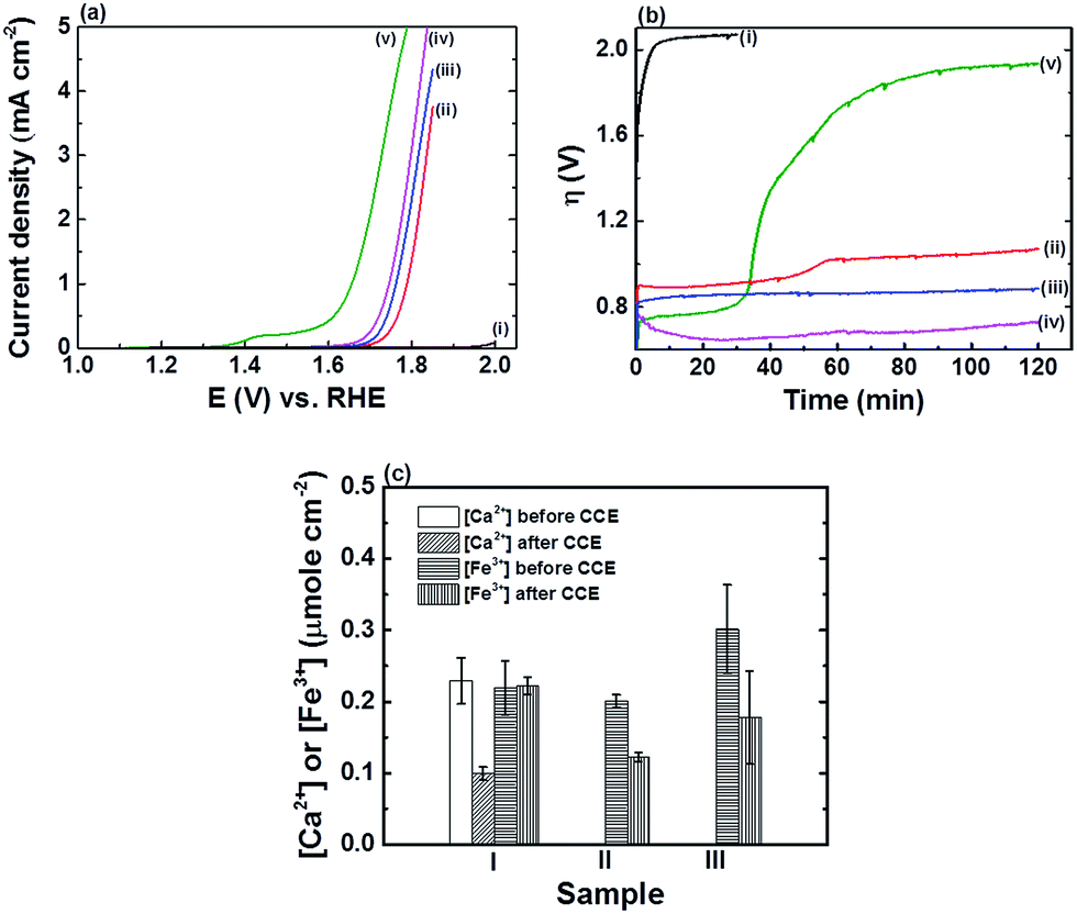 | ||
| Fig. 1 (a) LSVs, recorded at a scan rate of 10 mV s−1, and (b) η transients, recorded during CCE at an applied current density of 5 mA cm−2, of (i) bare FTO, (ii) FTO|CaFeOx(r=0), (iii) FTO|FeOx, (iv) FTO|CaFeOx(r=0.6), and (v) FTO|Co-Pi in phosphate buffer (0.1 M, pH 7). (c) The content of Ca2+ and Fe3+ in (I) FTO|CaFeOx(r=0.6), (II) FTO|CaFeOx(r=0), and (III) FTO|FeOx, quantified by using ICP, before and after 2 h CCE at an applied current density of 5 mA cm−2 in phosphate buffer (0.1 M, pH 7). | ||
| Samples | ||||
|---|---|---|---|---|
| FTO|CaFeOx(r=0) | FTO|FeOx | FTO|CaFeOx(r=0.6) | FTO|Co-Pi | |
| η 0 (V) | 0.86 ± 0.01 | 0.81 ± 0.01 | 0.74 ± 0.02 | 0.71 ± 0.04 |
| η f (V) | 1.04 ± 0.02 | 0.88 ± 0.03 | 0.76 ± 0.02 | 1.87 ± 0.06 |
As revealed, FTO|Co-Pi exhibited the highest electrocatalytic activity, in terms of η, towards the OER than the other iron based electrodes (Fig. 1a), but suffered instability under prolonged electrocatalysis at an applied current density of 5 mA cm−2 (Fig. 1b). The activity of FTO|Co-Pi degraded significantly and approached that of the bare FTO in the course of the CCE experiments. The instability of Co-Pi on a flat electrode at high applied current density has been reported previously (>5 mA cm−2) and was ascribed to the serious chemical dissolution of active Co species and absence of sufficient Co ions in phosphate buffer for the re-deposition (self-healing) of Co-Pi to compensate the loss of active Co species.9b,10 In contrast to rapid degradation of FTO|Co-Pi, all iron based electrodes exhibited superior stability; the stability, in terms of average increase in η (i.e., Δη: ηf − η0) during 2 h CCE, is in the order FTO|CaFeOx(r=0.6) (∼20 mV) > FTO|FeOx (∼70 mV) > FTO|CaFeOx(r=0.0) (∼180 mV) ≫ FTO|Co-Pi (∼1160 mV). The notable Δη for all the three Fe based modified electrodes can be attributed to the gradual pH drop in bulk solution of the anodic compartment and/or chemical dissolution (etching) of the active species by a significant drop in local pH near the electrode surface during the CCE experiments at high applied current density in the electrolyte of low buffering capability (0.1 M phosphate buffer). As the generation rate of protons from the OER at the anode is far faster than the removal rate of protons diffusing out of the anodic compartment to the cathodic compartment, protons accumulated in the anodic compartment, resulting in a pH drop in the bulk solution of the anodic compartment from 7.00 to 6.75 after 2 h CCE. This decrease in the pH of the bulk solution of the anodic compartment explains a Δη of about 15 mV during CCE experiments. On the other hand, the possibility of chemical dissolution for all iron based modified electrodes during CCE was examined by quantifying the amount of Fe species before and after 2 h CCE using ICP. The ICP analyses (Fig. 1c) reveal that the extent of dissolution of iron species from FTO|CaFeOx(r=0.6) was minimal (<1%) in contrast to those from FTO|CaFeOx(r=0) (∼39.2%) and FTO|FeOx (∼41.0%). The significant loss of active Fe species for FTO|CaFeOx(r=0) and FTO|FeOx explains their instability under prolonged electrolyses (Fig. 1b and S5†). Note that similar to previous reports,7d,8a significant loss (∼56.7%) in the redox-inert calcium content of FTO|CaFeOx(r=0.6) was observed after 2 h CCE. The loss in the calcium content mainly came from the surface calcium exposed to the electrolyte and is attributed to the interaction of FTO|CaFeOx(r=0.6) with phosphate electrolyte (vide infra).
As FTO|CaFeOx(r=0.6) is the most robust among the catalysts of interest, its electrocatalytic properties were subjected to further investigation. Fig. 2a & b show, respectively, the LSVs and η transients of FTO|CaFeOx(r=0.6) in phosphate buffer (0.1 M) of various pHs. As revealed, FTO|CaFeOx(r=0.6) exhibited the best activity at pH 7; the ηf for FTO|CaFeOx(r=0.6) to achieve a current density of 1 mA cm−2 is in the order pH 7 (0.57 ± 0.01 V) < pH 8 (0.61 ± 0.01 V) < pH 9 (0.67 ± 0.01 V) < pH 10 (0.69 ± 0.01 V) < pH 6 (0.70 ± 0.01 V). In addition, the maximal Δη was below 25 mV after 2 h CCE at pH > 7, suggesting that FTO|CaFeOx(r=0.6) is fairly stable in both neutral and mildly basic electrolyte solutions. Oxygen generated at FTO|CaFeOx(r=0.6) during CCE at an applied current density of 5 mA cm−2 at pH 7 was verified and quantified by in situ monitoring oxygen using a fluorescence O2 probe, and the typical oxygen evolution profile is shown in Fig. S6.† It can be found that the amount of oxygen evolved is almost close to the theoretical one, that is, the faradaic efficiency (FE) for oxygen generation from water oxidation is ∼100%, indicating all the applied charge in CCE is exclusively used for the OER.
 | ||
| Fig. 2 (a) LSVs, recorded at a scan rate of 10 mV s−1, and (b) η transients, recorded at an applied current density of 1 mA cm−2, of FTO|CaFeOx(r=0.6) in phosphate buffer (0.1 M) of (i) pH 6, (ii) pH 7, (iii) pH 8, (iv) pH 9, and (v) pH 10. | ||
Fig. 3 shows the η transients for FTO|CaFeOx(r=0.6) during 2 h CCE in phosphate buffer (pH 7) of various concentrations. As indicated, both η0 and Δη were significantly reduced when CCE, at an applied current density of 5 mA cm−2, was carried out in more concentrated phosphate buffer. In addition, direct conversion of CO2 in flue gas from the coal-firing power plant or exhaust gas from the steel mill has received much attention recently, and it is therefore of great importance to examine the applicability of FTO|CaFeOx(r=0.6) in the presence of these gas components. To this end, the OER activity of FTO|CaFeOx(r=0.6) under an artificial gas atmosphere composed of exhaust gas components from the steel mill, including 70% CO2, 10% CO, 10% CH4, and 10% H2, was examined. As can be seen in curve iv in Fig. 3, FTO|CaFeOx(r=0.6) exhibited similar activity and stability under an artificial gas atmosphere to that under a N2 atmosphere (curve iii in Fig. 3), suggesting its applicability to the OER under CO2 reduction in the presence of potential poisoning gases (e.g., CO). Note that the initial overpotential of FTO|CaFeOx(r=0.6) under an artificial gas atmosphere is slightly smaller than those under N2 and 100% CO2 atmospheres (Fig. S7†), suggesting that components (i.e., CO, CH4, and H2) in the artificial gas may work as sacrificial agents. It is also worth noting that as revealed in Fig. S8,† FTO|CaFeOx(r=0.6) is rather active and stable in sodium bicarbonate (1.0 M)–sodium carbonate (0.1 M) electrolyte solution, suggesting its applicability in CO2 reduction systems. Furthermore, FTO|CaFeOx(r=0.6) also displayed high activity and stability under an applied current density of 10 mA cm−2 (curve v in Fig. 3), a figure of merit commonly used in the synthesis of solar fuels, in phosphate buffer (1.0 M, pH 7); η increased slightly from about 0.65 to 0.68 V after 2 h CCE. In other words, an η of 0.65–0.68 V is required for FTO|CaFeOx(r=0.6) to maintain a turnover frequency (TOF) of 0.12 s−1. Note that the determined TOF value is based on the assumption that all of the iron centers involve in the OER, and therefore represents a lower bound for the activity of the catalyst.
 | ||
| Fig. 3 η transients, recorded at an applied current density of (i, ii, iii, and iv) 5 and (v) 10 mA cm−2, of FTO|CaFeOx(r=0.6) in (i) 0.1 M, (ii) 0.5 M, and (iii, iv, and v) 1.0 M phosphate buffer (pH 7) under (i, ii, iii, and v) N2 and (iv) artificial gas (70% CO2, 10% CH4, 10% H2, and 10% CO) atmospheres. Solution pH of phosphate buffer shifted from 7.0 to 6.7 under a purge of artificial gas. | ||
Mechanistic interpretation
As discussed in the preceding section, FTO|CaFeOx with r ≥ 0.05 is predominantly amorphous. Nevertheless, three broad peaks, characteristic to γ-Fe2O3,22 at 350 (T1), 500 (E), and 720 cm−1 (A1) and magnon mode in the neighborhood of 1350 cm−1 were observed in the Raman spectra (Fig. S9†) of both FTO|CaFeOx(r=0) and FTO|CaFeOx(r=0.6), suggesting that FTO|CaFeOx(r=0.6) contains a short-range order γ-Fe2O3 domain embedded in an amorphous Ca2Fe2O5 matrix.Fig. 4 shows the X-ray-absorption near-edge structure (XANES) spectra of the Fe K edge. As indicated, the white line signals of FTO|CaFeOx(r=0) and FTO|CaFeOx(r=0.6) are located at 7133 and 7132 eV, respectively. In addition, the white line feature of FTO|CaFeOx(r=0) is narrower and more intense than that of FTO|CaFeOx(r=0.6). These changes and shifted energies of the white line feature could be resulted from structural disorder or the decreased crystal size.23 Moreover the pre-edge energy of FTO|CaFeOx(r=0.6) is higher than that of FTO|CaFeOx(r=0), suggesting the ratio of Fe in the tetrahedral site to that in the octahedral site was increased.24 These results show that the symmetry of the central iron atom and the crystal size were affected by the incorporation of calcium. On the other hand, Ca K-edge XANES spectra of FTO|CaFeOx(r=0.6) (Fig. S10†) indicate that one major compound in FTO|CaFeOx(r=0.6) consists of Ca2Fe2O5.25
 | ||
| Fig. 4 Fe K-edge XANES spectra of FTO|CaFeOx(r=0) and FTO|CaFeOx(r=0.6). Inset: the enlarged Fe K-edge XANES spectra. | ||
The Fourier-transformed extended X-ray-absorption fine-structure (EXAFS) spectra of the Fe K-edge and the fitted results are shown in Fig. 5. It can be found that the major bond distances of the EXAFS spectra of FTO|CaFeOx(r=0) are similar to those of FTO|CaFeOx(r=0.6) (Fig. 5a). In addition, there is no difference in the amplitude and peak positions of FTO|CaFeOx(r=0) and FTO|CaFeOx(r=0.6) in the first shell (contributed from octahedral or tetrahedral Fe sites), but the amplitudes of FTO|CaFeOx(r=0.6) show a progressive decrease of the second and third shells (Fe–Fe1 and Fe–Fe2), which are contributed by edge sharing and corner sharing of the iron octahedral or tetrahedral structure at ∼2.5 to 3.5 Å. These phenomena were accompanied with altered spectral features between 2.5 Å and 3.5 Å.
 | ||
| Fig. 5 Fe K-edge EXAFS spectra (a) and fitting results for (b) FTO|CaFeOx(r=0) and (c) FTO|CaFeOx(r=0.6). | ||
The data in Fig. 5a were fitted (R-factor = 0.017) with an EXAFS model derived from an γ-Fe2O3 structural model that accounted for the highest-amplitude, single-scattering Fe–O, Fe–Fe1 and Fe–Fe2 out to 3.7 Å, and the best-fitted EXAFS results and the fitting paths for FTO|CaFeOx(r=0) and FTO|CaFeOx(r=0.6) are shown in Fig. 5b and c, respectively. The fitted structural parameters are summarized in Table 2. As can be seen, FTO|CaFeOx(r=0.6) exhibited a lower coordination number (CN; 4.51(0.32) vs. 5.17(0.14)) and shorter interatomic distance (R; 1.926 (0.010) vs. 1.962 (0.003) Å) in the Fe–O path than FTO|CaFeOx(r=0), which could be attributed to the decreasing number of octahedral sites. In addition, FTO|CaFeOx(r=0.6) also exhibited a lower CN (1.69 (0.33) vs. 3.07 (0.29)) than FTO|CaFeOx(r=0) in the second shell (Fe–Fe1 path), which could be ascribed to the increasing structural disorder and decreasing crystal size that result from the decreased edge-sharing of the octahedral structure after the inclusion of calcium. Analyses of the fits indicated that σ2 for the Fe–Fe1 paths of FTO|CaFeOx(r=0.6) increased from 0.009 to 0.010, which provides a consistent proof.
| Sample | Bond | CN | R/Å | σ 2/Å2 |
|---|---|---|---|---|
| a Fitting was done across the k range 2.5–10 Å−1 and R range 1.0–3.7 Å. The numbers in parentheses are uncertainties calculated for the EXAFS model. b All samples were fitted simultaneously, yielding a normalized sum of squared residuals [R-factor = ∑(data-fit)2/∑data2] 0.017 (0.17%) for FTO|CaFeOx(r=0) and FTO|CaFeOx(r=0.6). The values of other EXAFS model parameters not shown above were either fixed or fitted to a common value across all samples as follows: S02 = 0.78(0.02) (fixed amplitude reduction factor based on first-shell fitting of maghemite). ΔE = −0.05 and −2.945 eV (fitted energy-shift parameter). | ||||
| FTO|CaFeOx(r=0) | Fe–O | 5.17 (0.14) | 1.962 (0.003) | 0.009 (0.001) |
| Fe–Fe(1) | 3.07 (0.29) | 2.973 (0.007) | 0.009 (0.001) | |
| Fe–Fe(2) | 1.56 (0.60) | 3.784 (0.029) | 0.007 (0.004) | |
| FTO|CaFeOx(r=0.6) | Fe–O | 4.51 (0.32) | 1.926 (0.010) | 0.008 (0.002) |
| Fe–Fe(1) | 1.69 (0.33) | 3.011 (0.015) | 0.010 (0.002) | |
| Fe–Fe(2) | 1.11 (0.79) | 3.764 (0.056) | 0.011 (0.008) | |
FTO|CaFeOx(r=0.6) exhibited much higher activity and stability towards the OER than FTO|CaFeOx(r=0), which could be attributed to the difference in the local crystal structure flexibility. As the FeOECs catalyzed OER process involves the formation of surface intermediates, such as Fe(IV)![[double bond, length as m-dash]](https://www.rsc.org/images/entities/char_e001.gif) O,26 that induce the local structural distortion, the local structure of the lattice or its relaxation energy against the distortion strongly affects the stability of the intermediates and the activation energy of the surface reaction.27 Since amorphous materials have structural flexibility,27a the distortion energy required to form the structural distortion of the amorphous FTO|CaFeOx(r=0.6) for the OER is much smaller than that of FTO|CaFeOx(r=0) (or γ-Fe2O3). Accordingly, η along with the onset potential (Eonset) of the amorphous FTO|CaFeOx(r=0.6) for the OER is smaller than those of FTO|CaFeOx(r=0) (or γ-Fe2O3). It is interesting to note that FTO|CaFeOx(r=0.6) is more reactive towards phosphate ions than FTO|CaFeOx(r=0), resulting in the leaching of surface calcium and formation of iron phosphate. As indicated in Fig. 1c and Table S2,† leaching of calcium from FTO|CaFeOx(r=0.6) was observed not only after 2 h CCE at applied current densities of 1 and 5 mA cm−2, but also after simple immersion in phosphate buffer, suggesting that the leaching of calcium mainly resulted from the interaction between CaFeOx(r=0.6) and phosphate electrolyte. In addition, the leaching of calcium mainly came from the surface exposed to the electrolyte as the bulk Ca/Fe molar ratio (∼0.45), determined by ICP (Fig. 1c) of FTO|CaFeOx(r=0.6) after 2 h CCE was much higher than that of the surface one (0.08) determined by XPS (Table S2†). Moreover, as shown in Fig. S11a,† changes in iron and calcium contents of FTO|CaFeOx(r=0.6) were minimal after FTO|CaFeOx(r=0.6) was subjected to repetitive 2 h CCEs (Fig. S11b†), suggesting that further leaching of iron and calcium by repetitive electrolysis is not possible and further confirming that the leaching of calcium is limited to the surface (Fig. S11a†). On the other hand, as revealed in Fig. 6, both the as-prepared FTO|CaFeOx(r=0) and FTO|CaFeOx(r=0.6) exhibited similar electrochemical behaviour; cyclic voltammetry (CV) of both FTO|CaFeOx(r=0) and FTO|CaFeOx(r=0.6) exhibited an irreversible cathodic wave, which resulted from the reductive dissolution process of iron oxide (eqn (1)), and a small hump at around 0.4 V vs. the RHE, which is related to the oxidation of ferrous ions that are released from reductive dissolution of iron oxide (eqn (1)):28
O,26 that induce the local structural distortion, the local structure of the lattice or its relaxation energy against the distortion strongly affects the stability of the intermediates and the activation energy of the surface reaction.27 Since amorphous materials have structural flexibility,27a the distortion energy required to form the structural distortion of the amorphous FTO|CaFeOx(r=0.6) for the OER is much smaller than that of FTO|CaFeOx(r=0) (or γ-Fe2O3). Accordingly, η along with the onset potential (Eonset) of the amorphous FTO|CaFeOx(r=0.6) for the OER is smaller than those of FTO|CaFeOx(r=0) (or γ-Fe2O3). It is interesting to note that FTO|CaFeOx(r=0.6) is more reactive towards phosphate ions than FTO|CaFeOx(r=0), resulting in the leaching of surface calcium and formation of iron phosphate. As indicated in Fig. 1c and Table S2,† leaching of calcium from FTO|CaFeOx(r=0.6) was observed not only after 2 h CCE at applied current densities of 1 and 5 mA cm−2, but also after simple immersion in phosphate buffer, suggesting that the leaching of calcium mainly resulted from the interaction between CaFeOx(r=0.6) and phosphate electrolyte. In addition, the leaching of calcium mainly came from the surface exposed to the electrolyte as the bulk Ca/Fe molar ratio (∼0.45), determined by ICP (Fig. 1c) of FTO|CaFeOx(r=0.6) after 2 h CCE was much higher than that of the surface one (0.08) determined by XPS (Table S2†). Moreover, as shown in Fig. S11a,† changes in iron and calcium contents of FTO|CaFeOx(r=0.6) were minimal after FTO|CaFeOx(r=0.6) was subjected to repetitive 2 h CCEs (Fig. S11b†), suggesting that further leaching of iron and calcium by repetitive electrolysis is not possible and further confirming that the leaching of calcium is limited to the surface (Fig. S11a†). On the other hand, as revealed in Fig. 6, both the as-prepared FTO|CaFeOx(r=0) and FTO|CaFeOx(r=0.6) exhibited similar electrochemical behaviour; cyclic voltammetry (CV) of both FTO|CaFeOx(r=0) and FTO|CaFeOx(r=0.6) exhibited an irreversible cathodic wave, which resulted from the reductive dissolution process of iron oxide (eqn (1)), and a small hump at around 0.4 V vs. the RHE, which is related to the oxidation of ferrous ions that are released from reductive dissolution of iron oxide (eqn (1)):28
| Fe2O3(s) + 6H(aq)+ + 2e− ⇄ 2Fe(aq)2+ + 3H2O(l) | (1) |
 | ||
| Fig. 6 CVs, recorded at a scan rate of 10 mV s−1, of (a) FTO|CaFeOx(r=0) and (b) FTO|CaFeOx(r=0.6) in phosphate buffer (0.1 M, pH 7). Black dot trace, red dash trace, and blue solid trace represent the CVs of the as-prepared samples, sample after 2 h immersion in phosphate buffer (0.1 M, pH 7), and sample after 2 h CCE at an applied current density of 1 mA cm−2 in phosphate buffer (0.1 M, pH 7), respectively. | ||
However, in contrast to FTO|CaFeOx(r=0), FTO|CaFeOx(r=0.6) exhibited an additional quasi-reversible redox couple either after CCE at an applied current density of 1 mA cm−2 or immersion in phosphate buffer (0.1 M, pH 7) for 2 h. The midpoint potential (∼0.33 V vs. the RHE) is similar to that reported previously,28b,29 but about 0.1 V more positive than that of eqn (1) observed for FTO|CaFeOx(r=0), suggesting the formation of iron phosphate after these treatments. The corresponding electrochemical reaction(s) for this redox couple can be written as eqn (2) and (3):28b,29
| Fe(ad)2+ + HPO4(aq)2− ⇄ FePO4(s) + H(aq)+ + e− | (2) |
| Fe(ad)2+ + H2PO4(aq)− ⇄ FePO4(s) + 2H(aq)+ + e− | (3) |
The existence of iron phosphate can also be supported by XPS analyses for FTO|CaFeOx(r=0) and FTO|CaFeOx(r=0.6) before and after 2 h CCE (Fig. S12 and Table S2†). As revealed in Fig. S12,† after 2 h CCE at 1 mA cm−2, a positive shift in the BE of the Fe 2p3/2 peak (710.4 to 711.4 eV) and the appearance of an additional O 1s peak at a BE of 531.2 eV along with a P 2p3/2 peak at 133.3 eV were observed for CaFeOx(r=0.6). As the BE of the Fe 2p3/2 peak for iron phosphate is in the range between 711.8 and 712.9 eV,30 this positive shift in the BE of the Fe 2p3/2 peak along with the appearance of O 1s and P 2p peaks for CaFeOx(r=0.6) would support the formation of iron phosphate on the surface of CaFeOx(r=0.6) after 2 h CCE. Note that the BE of the Fe 2p3/2 peak for CaFeOx(r=0) remains unchanged after 2 h CCE, further confirming the absence of iron phosphate after electrolysis. The formation of iron phosphate on FTO|CaFeOx(r=0.6) explains the much higher P/Fe molar ratio of FTO|CaFeOx(r=0.6) after immersion and CCE treatments than that of FTO|CaFeOx(r=0) (Table S2†). In addition, as revealed in Fig. S13,† the P/Fe atomic ratio, measured by EDX after different periods of electrolysis at an applied current density of 5 mA cm−2, for FTO|CaFeOx(r=0.6) increased significantly during 60 min and 120 min, but slowly after 120 min, suggesting surface CaFeOx(r=0.6) transformed into iron phosphate progressively. Moreover, as indicated in Fig. S14,† iron phosphate itself is not a good OER catalyst as compared with CaFeOx(r=0.6), and the progressive transformation of active CaFeOx(r=0.6) into much less active iron phosphate is therefore considered as one of the main factors causing the progressive increase in η during CCE (Fig. 1b and 3). Note that the P/Fe atomic ratio measured using EDX (Fig. S13†) is much less than that measured using XPS (Table 2), suggesting that the formation of iron phosphate is limited to the surface. On the other hand, the in situ formation of iron phosphate could play a beneficial role in stabilizing the OER activity of FTO|CaFeOx(r=0.6) by preventing the chemical dissolution of active iron species (Fig. 1c). To prove this, FTO|CaFeOx(r=0) was surface-modified with iron phosphate using a CV pretreatment procedure reported previously,28b and subjected to 2 h-CCE at an applied current density of 5 mA cm−2 in phosphate buffer (0.1 M, pH 7). The CV (Fig. S15a†) of FTO|CaFeOx(r=0) confirms the formation of iron phosphate on FTO|CaFeOx(r=0) after CV pretreatment.28b,29 In addition, the typical η transient during CCE at an applied current density of 5 mA cm−2, shown in Fig. S15b,† indicates that iron phosphate modified FTO|CaFeOx(r=0) exhibited better stability than the as-prepared FTO|CaFeOx(r=0); Δη for iron phosphate modified FTO|CaFeOx(r=0) after 2 h CCE was about 120 mV, which is 60 mV less than that for the as-prepared FTO|CaFeOx(r=0). The beneficial role of iron phosphate in preventing active iron species from chemical dissolution by protons can also be confirmed by the results from CCE at higher applied current density. Fig. S16† shows the η transients for FTO|CaFeOx(r=0.6) and FTO|FeOx at an applied current density of 10 mA cm−2 in phosphate buffer (1.0 M, pH 7). As revealed, FTO|FeOx deactivated much quickly than at lower applied current density (Fig. 1b and S5†), but CaFeOx(r=0.6) remained stable. A previous report13b suggests that electrosynthesized FeOx doesn't form iron phosphate on its surface during electrolysis, and without this protecting layer, the deactivation of FeOx by the chemical dissolution was speeded up at higher applied current density. The actual mechanism is still under investigation, but the enhancement in stability by iron phosphate is more possibly related to the capability of surface iron phosphate to take up the protons, released from the OER, and transfer protons to phosphate ions nearby promptly; this in situ formed proton-relay layer in-between the electrolyte and electrode surface prevents the direct contact of active iron species with protons and thus prevents the loss of active iron species during the electrolysis.
From the above discussion, we speculate that amorphous Ca2Fe2O5 on the surface of FTO|CaFeOx(r=0.6) started to decompose upon exposure to phosphate electrolyte, resulting in the leaching of the surface calcium and formation of iron phosphate. The decomposition of FTO|CaFeOx(r=0.6) stopped after the surface of the decomposed FTO|CaFeOx(r=0.6) was fully covered a layer of iron phosphate. It is interesting to note that there is a difference in transient behaviour between the first and second CCE experiments (Fig. S11b†); a decrease in η was only observed within the first 30 min of the first CCE. As the decomposition process only occurred in the first CCE, we postulated that the decrease in η within the first 30 min of the first CCE was related to the decomposition process.
Application in photoelectrochemical water splitting
Bismuth vanadate (BiVO4), an earth-abundant n-type semiconductor, has a moderate bandgap of 2.4 eV and favorable valence band potential (2.3 V vs. the RHE) for water oxidation, which makes it a promising photoanode material for PEC water oxidation.31 Nevertheless, the typical PEC performance of pristine BiVO4 photoanodes towards the OER is not impressive as they suffer from serious electron–hole charge recombination, poor electrical conductivity, and sluggish water oxidation kinetics.31c Here, we demonstrate that CaFeOx(r=0.6) can be used as an inexpensive and active OEC in improving the OER kinetics at the BiVO4 photoanode. The BiVO4 photoanode, denoted as FTO|BiVO4, was prepared by using a similar procedure reported previously,32 and its surface modification with CaFeOx(r=0.6) was achieved by spin-coating a precursor solution containing 0.2 M iron(III) nitrate, 0.3 M ethanolamine, and 0.12 M calcium acetate onto its surface and follow-up thermal annealing (see the Experimental section). As revealed in the SEM images, shown in Fig. S17a and b,† no dramatic change in the surface morphology of FTO|BiVO4 after surface modification with CaFeOx(r=0.6), but as indicated by the HRTEM image shown in the inset of Fig. S17c,† the surface of FTO|BiVO4 appeared to be covered with an amorphous thin CaFeOx layer of ∼5 nm in thickness. In addition, the atomic ratio of Ca:Fe:Bi:V:O = 1.1:1.7:17.8:17.8:61.5 obtained by energy dispersive X-ray spectroscopy (EDS, Fig. S17d†) confirms the presence of calcium and iron in CaFeOx(r=0.6) modified FTO|BiVO4.
The PEC characteristics of pristine FTO|BiVO4 and CaFeOx(r=0.6) modified FTO|BiVO4, denoted as FTO|BiVO4|CaFeOx(r=0.6), were investigated in phosphate buffer (1.0 M, pH 7) using LSV and controlled-potential electrolysis at an applied potential of 1.23 V vs. the RHE, and the results are shown in Fig. 7. As revealed in Fig. 7a, modification of FTO|BiVO4 with CaFeOx(r=0.6) yielded a significant cathodic shift (0.3 vs. 0.46 V vs. the RHE) in the Eonset of the photocurrent response and a substantial enhancement in the photocurrent response (1.22 vs. 0.58 mA cm−2 at an applied potential of 1.2 V vs. the RHE) as compared to pristine FTO|BiVO4. In addition, FTO|BiVO4|CaFeOx(r=0.6) exhibited a PEC performance close to pristine FTO|BiVO4 in the presence of a Na2SO3 hole scavenger (photocurrent transient ii vs. iii in Fig. 7a) that indicates the beneficial role of CaFeOx(r=0.6) in improving the kinetics of the OER and interfacial hole transfer, resulting in a remarkable enhancement in the PEC performance of FTO|BiVO4.
 | ||
| Fig. 7 (a) LSVs, recorded at a scan rate of 10 mV s−1, of (i) FTO|BiVO4 and (ii and iii) FTO|BiVO4|CaFeOx(r=0.6) in phosphate buffer (1.0 M, pH 7, i and ii) or in Na2SO3 (1.0 M, pH 9.6, iii) under chopped light illumination (100 mW cm−2). (b) Photocurrent density transients, recorded at an applied potential of 1.23 V vs. the RHE, of (i) FTO|BiVO4 and (ii) FTO|BiVO4|CaFeOx(r=0.6) in phosphate buffer (1.0 M, pH 7) under light illumination (100 mW cm−2). | ||
Furthermore, as indicated in Fig. 7b, the photostability of FTO|BiVO4 was also significantly improved after surface modification with CaFeOx(r=0.6); after 2 h light illumination at an applied potential of 1.23 V vs. the RHE, FTO|BiVO4|CaFeOx(r=0.6) retained about 85% of its initial photocurrent, whereas un-modified FTO|BiVO4 only retained 37% of its initial photocurrent. The photo-instability of BiVO4 has been reported previously, and ascribed mainly to the structural destabilization by the surface-accumulated photo-generated holes and chemical attack via vanadium loss into solution.33 As a result, the improvement in the photostability of BiVO4 by interfacing with CaFeOx(r=0.6) further confirms the beneficial role of CaFeOx(r=0.6) in improving the kinetics of the OER, preventing photocorrosion induced by the surface-accumulated holes.33 Finally, after light illumination at an applied potential of 1.23 V vs. the RHE for 2 h, the amount of charge passage and oxygen detected was 5.7C and 11.7 μmole, respectively, corresponding to a FE of ∼80%. Note that there is still room for improvement in PEC performance, including Eonset and the photocurrent response of FTO|BiVO4|CaFeOx(r=0.6), as the parameters of the surface-modification procedure have not been optimized and the PEC experiments were carried out in highly concentrated phosphate buffer, which accelerates the degradation of BiVO4.33
Conclusions
A CaFeOx thin film with controllable calcium content was prepared by a simple and scalable spin-coating method followed by annealing at moderate temperature (400 °C). CaFeOx(r=0) had a γ-Fe2O3 crystalline phase, whereas CaFeOx(r≥ 0.05) was amorphous. In contrast to CaFeOx(r=0), CaFeOx(r=0.6) showed reactivity to the phosphate ions to form an iron phosphate protection layer preventing the loss of active iron species. We ascribed the calcium-induced difference in crystallinity (or structural flexibility) along with surface reactivity (or formation of iron phosphate) to the enhanced catalytic activity, in terms of i0 and η and the stability of CaFeOx. With optimal calcium content (r = 0.6), the excellent activity and stability of CaFeOx place it among the most active earth-abundant material based OECs in neutral aqueous media. Upon being integrated onto the BiVO4 photoanode, CaFeOx was also demonstrated as an efficient cocatalyst in improving the photocurrent response and photostability of the BiVO4 photoanode.Conflicts of interest
There are no conflicts to declare.Acknowledgements
Financial support from the Ministry of Science and Technology of Taiwan (105-2221-E-006-230-MY2, 105-ET-E-006-006-ET, 105-2112-M-213-004-MY3, and 105-2218-E-110-004-MY3) and the Ministry of Education, Taiwan (The Aim for the Top University Project to the National Cheng Kung University (NCKU)) is acknowledged. Technical support from Prof. Jih-Jen Wu is also gratefully acknowledged.References
- (a) T. A. Betley, Q. Wu, T. Van Voorhis and D. G. Nocera, Inorg. Chem., 2008, 47, 1849 CrossRef CAS PubMed; (b) R. I. Cukier and D. G. Nocera, Annu. Rev. Phys. Chem., 1998, 49, 337 CrossRef CAS PubMed; (c) M. H. V. Huynh and T. J. Meyer, Chem. Rev., 2007, 107, 5004 CrossRef CAS PubMed.
- (a) R. L. Doyle, I. J. Godwin, M. P. Brandon and M. E. G. Lyons, Phys. Chem. Chem. Phys., 2013, 15, 13737 RSC; (b) T. Reier, M. Oezaslan and P. Strasser, ACS Catal., 2012, 2, 1765 CrossRef CAS; (c) Y. Lee, J. Suntivich, K. J. May, E. E. Perry and Y. Shao-Horn, J. Phys. Chem. Lett., 2012, 3, 399 CrossRef CAS PubMed; (d) A. Harriman, I. J. Pickering, J. M. Thomas and P. A. Christensen, J. Chem. Soc., Faraday Trans., 1988, 84, 2795 RSC.
- (a) S. Cobo, J. Heidkamp, P. A. Jacques, J. Fize, V. Fourmond, L. Guetaz, B. Jousselme, V. Ivanova, H. Dau, S. Palacin, M. Fontecave and V. Artero, Nat. Mater., 2012, 11, 802 CrossRef CAS PubMed; (b) Y. Surendranath, M. W. Kanan and D. G. Nocera, J. Am. Chem. Soc., 2010, 132, 16501 CrossRef CAS PubMed; (c) M. Dinca, Y. Surendranath and D. G. Nocera, Proc. Natl. Acad. Sci. U. S. A., 2010, 107, 10337 CrossRef CAS PubMed; (d) M. W. Kanan and D. G. Nocera, Science, 2008, 321, 1072 CrossRef CAS PubMed; (e) D. Gonzalez-Flores, I. Zaharieva, J. Heidkamp, P. Chernev, E. Martinez-Moreno, C. Pasquini, M. R. Mohammadi, K. Klingan, U. Gernet, A. Fischer and H. Dau, ChemSusChem, 2016, 9, 379 CrossRef CAS PubMed; (f) S. Haschke, Y. L. Wu, M. Bashouti, S. Christiansen and J. Bachmann, ChemCatChem, 2015, 7, 2455 CrossRef CAS; (g) M. X. Chen, Y. Z. Wu, Y. Z. Han, X. H. Lin, J. L. Sun, W. Zhang and R. Cao, ACS Appl. Mater. Interfaces, 2015, 7, 21852 CrossRef CAS PubMed; (h) J. Park, H. Kim, K. Jin, B. J. Lee, Y. S. Park, H. Kim, I. Park, K. D. Yang, H. Y. Jeong, J. Kim, K. T. Hong, H. W. Jang, K. Kang and K. T. Nam, J. Am. Chem. Soc., 2014, 136, 4201 CrossRef CAS PubMed; (i) S. Y. Lee, D. Gonzalez-Flores, J. Ohms, T. Trost, H. Dau, I. Zaharieva and P. Kurz, ChemSusChem, 2014, 7, 3442 CrossRef CAS PubMed; (j) K. Jin, J. Park, J. Lee, K. D. Yang, G. K. Pradhan, U. Sim, D. Jeong, H. L. Jang, S. Park, D. Kim, N. E. Sung, S. H. Kim, S. Han and K. T. Nam, J. Am. Chem. Soc., 2014, 136, 7435 CrossRef CAS PubMed; (k) W. D. Chemelewski, H. C. Lee, J. F. Lin, A. J. Bard and C. B. Mullins, J. Am. Chem. Soc., 2014, 136, 2843 CrossRef CAS PubMed; (l) J. A. Seabold and K. S. Choi, J. Am. Chem. Soc., 2012, 134, 2186 CrossRef CAS PubMed; (m) A. Ramirez, P. Bogdanoff, D. Friedrich and S. Fiechter, Nano Energy, 2012, 1, 282 CrossRef CAS; (n) J. S. Kanady, E. Y. Tsui, M. W. Day and T. Agapie, Science, 2011, 333, 733 CrossRef CAS PubMed; (o) G. Park, Y. I. Kim, Y. H. Kim, M. Park, K. Y. Jang, H. Song and K. M. Nam, Nanoscale, 2017, 9, 4751 RSC; (p) Y. H. Lai, C. Y. Lin, Y. K. Lv, T. C. King, A. Steiner, N. M. Muresan, L. H. Gan, D. S. Wright and E. Reisner, Chem. Commun., 2013, 49, 4331 RSC; (q) Y. H. Lai, T. C. King, D. S. Wright and E. Reisner, Chem.–Eur. J., 2013, 19, 12943 CrossRef CAS PubMed.
- (a) Y. Hori and S. Suzuki, J. Electrochem. Soc., 1983, 130, 2387 CrossRef CAS; (b) T. E. Teeter and P. Vanrysselberghe, J. Chem. Phys., 1954, 22, 759 CrossRef CAS; (c) P. Vanrysselberghe, G. J. Alkire and J. M. McGee, J. Am. Chem. Soc., 1946, 68, 2050 CrossRef CAS.
- (a) G. Ananyev and G. C. Dismukes, Photosynth. Res., 2005, 84, 355 CrossRef CAS PubMed; (b) K. N. Ferreira, T. M. Iverson, K. Maghlaoui, J. Barber and S. Iwata, Science, 2004, 303, 1831 CrossRef CAS PubMed; (c) P. Geijer, F. Morvaridi and S. Styring, Biochemistry, 2001, 40, 10881 CrossRef CAS PubMed; (d) I. Vass and S. Styring, Biochemistry, 1991, 30, 830 CrossRef CAS PubMed.
- (a) K. Beckmann, H. Uchtenhagen, G. Berggren, M. F. Anderlund, A. Thapper, J. Messinger, S. Styring and P. Kurz, Energy Environ. Sci., 2008, 1, 668 RSC; (b) R. Brimblecombe, A. Koo, G. C. Dismukes, G. F. Swiegers and L. Spiccia, J. Am. Chem. Soc., 2010, 132, 2892 CrossRef CAS PubMed; (c) M. Yagi and K. Narita, J. Am. Chem. Soc., 2004, 126, 8084 CrossRef CAS PubMed; (d) J. Limburg, J. S. Vrettos, H. Y. Chen, J. C. de Paula, R. H. Crabtree and G. W. Brudvig, J. Am. Chem. Soc., 2001, 123, 423 CrossRef CAS PubMed; (e) J. Limburg, G. W. Brudvig and R. H. Crabtree, J. Am. Chem. Soc., 1997, 119, 2761 CrossRef CAS; (f) M. M. Najafpour and A. N. Moghaddam, Dalton Trans., 2012, 41, 10292 RSC; (g) R. Brimblecombe, D. R. J. Kolling, A. M. Bond, G. C. Dismukes, G. F. Swiegers and L. Spiccia, Inorg. Chem., 2009, 48, 7269 CrossRef CAS PubMed; (h) R. Brimblecombe, G. F. Swiegers, G. C. Dismukes and L. Spiccia, Angew. Chem., Int. Ed., 2008, 47, 7335 CrossRef CAS PubMed.
- (a) A. Yamaguchi, R. Inuzuka, T. Takashima, T. Hayashi, K. Hashimoto and R. Nakamura, Nat. Commun., 2014, 5, 4265 Search PubMed; (b) T. Takashima, K. Hashimoto and R. Nakamura, J. Am. Chem. Soc., 2012, 134, 1519 CrossRef CAS PubMed; (c) T. Takashima, K. Hashimoto and R. Nakamura, J. Am. Chem. Soc., 2012, 134, 18153 CrossRef CAS PubMed; (d) M. M. Najafpour, K. C. Leonard, F. R. F. Fan, M. A. Tabrizi, A. J. Bard, C. K. King'ondu, S. L. Suib, B. Haghighi and S. I. Allakhverdiev, Dalton Trans., 2013, 42, 5085 RSC.
- (a) M. M. Najafpour, T. Ehrenberg, M. Wiechen and P. Kurz, Angew. Chem., Int. Ed., 2010, 49, 2233 CrossRef CAS PubMed; (b) I. Zaharieva, D. Gonzalez-Flores, B. Asfari, C. Pasquini, M. R. Mohammadi, K. Klingan, I. Zizak, S. Loos, P. Chernev and H. Dau, Energy Environ. Sci., 2016, 9, 2433 RSC; (c) E. Y. Tsui, R. Tran, J. Yano and T. Agapie, Nat. Chem., 2013, 5, 293 CrossRef CAS PubMed; (d) E. Y. Tsui and T. Agapie, Proc. Natl. Acad. Sci. U. S. A., 2013, 110, 10084 CrossRef CAS PubMed.
- (a) Y. Surendranath, M. Dinca and D. G. Nocera, J. Am. Chem. Soc., 2009, 131, 2615 CrossRef CAS PubMed; (b) D. A. Lutterman, Y. Surendranath and D. G. Nocera, J. Am. Chem. Soc., 2009, 131, 3838 CrossRef CAS PubMed.
- A. Minguzzi, F. R. F. Fan, A. Vertova, S. Rondinini and A. J. Bard, Chem. Sci., 2012, 3, 217 RSC.
- C. C. L. McCrory, S. H. Jung, J. C. Peters and T. F. Jaramillo, J. Am. Chem. Soc., 2013, 135, 16977 CrossRef CAS PubMed.
- (a) M. E. G. Lyons, R. L. Doyle and M. P. Brandon, Phys. Chem. Chem. Phys., 2011, 13, 21530 RSC; (b) M. E. G. Lyons and M. P. Brandon, Phys. Chem. Chem. Phys., 2009, 11, 2203 RSC.
- (a) T. W. Kim and K. S. Choi, Science, 2014, 343, 990 CrossRef CAS PubMed; (b) Y. Z. Wu, M. X. Chen, Y. Z. Han, H. X. Luo, X. J. Su, M. T. Zhang, X. H. Lin, J. L. Sun, L. Wang, L. Deng, W. Zhang and R. Cao, Angew. Chem., Int. Ed., 2015, 54, 4870 CrossRef CAS PubMed.
- (a) S. Poulin, R. Franca, L. Moreau-Belanger and E. Sacher, J. Phys. Chem. C, 2010, 114, 10711 CrossRef CAS; (b) A. P. Grosvenor, B. A. Kobe, M. C. Biesinger and N. S. McIntyre, Surf. Interface Anal., 2004, 36, 1564 CrossRef CAS.
- L. X. Zhang, J. H. Zhao, H. Q. Lu, L. Li, J. F. Zheng, H. Li and Z. P. Zhu, Sens. Actuators, B, 2012, 161, 209 CrossRef CAS.
- S. L. Stipp and M. F. Hochella, Geochim. Cosmochim. Acta, 1991, 55, 1723 CrossRef CAS.
- (a) W. Gu, D. W. Bousfield and C. P. Tripp, J. Mater. Chem., 2006, 16, 3312 RSC; (b) T. Sugama, L. E. Kukacka, N. Carciello and N. J. Hocker, Cem. Concr. Res., 1989, 19, 857 CrossRef CAS.
- R. Koirala, K. R. Gunugunuri, S. E. Pratsinis and P. G. Smirniotis, J. Phys. Chem. C, 2011, 115, 24804 CAS.
- (a) A. Sutka, M. Kodu, R. Parna, R. Saar, I. Juhnevica, R. Jaaniso and V. Kisand, Sens. Actuators, B, 2016, 224, 260 CrossRef CAS; (b) Y. Obukuro, K. Obata, R. Maeda, S. Matsushima, Y. Okuyama, N. Matsunaga and G. Sakai, J. Ceram. Soc. Jpn., 2015, 123, 995 CrossRef CAS.
- S. Dhankhar, K. Gupta, G. Bhalerao, N. Shukla, M. Chandran, B. Francis, B. Tiwari, K. Baskar and S. Singh, RSC Adv., 2015, 5, 92549 RSC.
- B. J. Xue, J. Luo, F. Zhang and Z. Fang, Energy, 2014, 68, 584 CrossRef CAS.
- (a) Y. El Mendili, J. F. Bardeau, N. Randrianantoandro, A. Gourbil, J. M. Greneche, A. M. Mercier and F. Grasset, J. Raman Spectrosc., 2011, 42, 239 CrossRef CAS; (b) D. L. A. deFaria, S. V. Silva and M. T. deOliveira, J. Raman Spectrosc., 1997, 28, 873 CrossRef CAS.
- L. X. Chen, T. Liu, M. C. Thurnauer, R. Csencsits and T. Rajh, J. Phys. Chem. B, 2002, 106, 8539 CrossRef CAS.
- (a) M. L. Fdez-Gubieda, A. García-Prieto, J. Alonso and C. Meneghini, in Iron Oxides: from Nature to Applications, ed. D. Faivre, Wiley-VCH Verlag GmbH & Co. KGaA, Weinheim, Germany, 1st edn, 2016, ch. 17, pp. 397–412 Search PubMed; (b) M. Wilke, F. Farges, P.-E. Petit, G. E. Brown and F. Martin, Am. Mineral., 2001, 86, 714 CrossRef CAS.
- M. Kimura, Y. Uemura, T. Takayama, R. Murao, K. Asakura and M. Nomura, J. Phys.: Conf. Ser., 2013, 430, 012074 CrossRef.
- (a) B. Klahr, S. Gimenez, F. Fabregat-Santiago, J. Bisquert and T. W. Hamann, Energy Environ. Sci., 2012, 5, 7626 RSC; (b) A. Hellman and R. G. S. Pala, J. Phys. Chem. C, 2011, 115, 12901 CrossRef CAS; (c) D. L. Popescu, M. Vrabel, A. Brausam, P. Madsen, G. Lente, I. Fabian, A. D. Ryabov, R. van Eldik and T. J. Collins, Inorg. Chem., 2010, 49, 11439 CrossRef CAS PubMed; (d) W. C. Ellis, N. D. McDaniel, S. Bernhard and T. J. Collins, J. Am. Chem. Soc., 2010, 132, 10990 CrossRef CAS PubMed; (e) J. U. Rohde, J. H. In, M. H. Lim, W. W. Brennessel, M. R. Bukowski, A. Stubna, E. Munck, W. Nam and L. Que, Science, 2003, 299, 1037 CrossRef CAS PubMed.
- (a) E. Tsuji, A. Imanishi, K. Fukui and Y. Nakato, Electrochim. Acta, 2011, 56, 2009 CrossRef CAS; (b) A. Imanishi, T. Okamura, N. Ohashi, R. Nakamura and Y. Nakato, J. Am. Chem. Soc., 2007, 129, 11569 CrossRef CAS PubMed; (c) R. Nakamura, T. Okamura, N. Ohashi, A. Imanishi and Y. Nakato, J. Am. Chem. Soc., 2005, 127, 12975 CrossRef CAS PubMed; (d) R. Nakamura, N. Ohashi, A. Imanishi, T. Osawa, Y. Matsumoto, H. Koinuma and Y. Nakato, J. Phys. Chem. B, 2005, 109, 1648 CrossRef CAS PubMed.
- (a) K. J. McKenzie and F. Marken, Pure Appl. Chem., 2001, 73, 1885 CrossRef CAS; (b) C. Y. Lin and C. T. Chang, Sens. Actuators, B, 2015, 220, 695 CrossRef CAS.
- F. Marken, D. Patel, C. E. Madden, R. C. Millward and S. Fletcher, New J. Chem., 2002, 26, 259 RSC.
- (a) P. Nagaraju, C. Srilakshmi, N. Pasha, N. Lingaiah, I. Suryanarayana and P. S. S. Prasad, Appl. Catal., A, 2008, 334, 10 CrossRef CAS; (b) D. H. Yu, C. Wu, Y. Kong, N. H. Xue, X. F. Guo and W. P. Ding, J. Phys. Chem. C, 2007, 111, 14394 CrossRef CAS; (c) Y. Wang, Q. Yuan, Q. H. Zhang and W. P. Deng, J. Phys. Chem. C, 2007, 111, 2044 CrossRef CAS.
- (a) C. M. Suarez, S. Hernandez and N. Russo, Appl. Catal., A, 2015, 504, 158 CrossRef; (b) Z. F. Huang, L. Pan, J. J. Zou, X. W. Zhang and L. Wang, Nanoscale, 2014, 6, 14044 RSC; (c) Y. Park, K. J. McDonald and K. S. Choi, Chem. Soc. Rev., 2013, 42, 2321 RSC.
- K. J. McDonald and K. S. Choi, Energy Environ. Sci., 2012, 5, 8553 CAS.
- F. M. Toma, J. K. Cooper, V. Kunzelmann, M. T. McDowell, J. Yu, D. M. Larson, N. J. Borys, C. Abelyan, J. W. Beeman, K. M. Yu, J. H. Yang, L. Chen, M. R. Shaner, J. Spurgeon, F. A. Houle, K. A. Persson and I. D. Sharp, Nat. Commun., 2016, 7, 12012 CrossRef PubMed.
Footnote |
| † Electronic supplementary information (ESI) available. See DOI: 10.1039/c7se00447h |
| This journal is © The Royal Society of Chemistry 2018 |