 Open Access Article
Adhesive bacterial amyloid nanofiber-mediated growth of metal–organic frameworks on diverse polymeric substrates†
Cuizheng
Zhang‡
a,
Yingfeng
Li‡
abc,
Hongliang
Wang
a,
Sanfeng
He
a,
Yiyi
Xu
a,
Chao
Zhong
*a and
Tao
Li
 *a
*a
aSchool of Physical Science and Technology, ShanghaiTech University, Shanghai, China 201210. E-mail: litao1@shanghaitech.edu.cn; zhongchao@shanghaitech.edu.cn
bShanghai Institute of Ceramics, Chinese Academy of Sciences, Shanghai, China 200050
cUniversity of Chinese Academy of Sciences, Beijing, China 100049
First published on 1st June 2018
Abstract
The development of a simple, robust, and generalizable approach for spatially controlled growth of metal–organic frameworks (MOFs) on diverse polymeric substrates is of profound technological significance but remains a major challenge. Here, we reported the use of adhesive bacterial amyloid nanofibers, also known as curli nanofibers (CNFs), major protein components of bacterial biofilms, as universal and chemically/mechanically robust coatings on various polymeric substrates to achieve controlled MOF growth with improved surface coverage up to 100-fold. Notably, owing to the intrinsic adhesive attributes of CNFs, our approach is applicable for MOF growth on both 2D surfaces and 3D objects regardless of their geometric complexity. Applying this technique to membrane fabrication afforded a thin-film composite membrane comprising a 760 ± 80 nm ZIF-8 selective layer grown on a microporous polyvinylidene fluoride (PVDF) support which exhibited a C3H6/C3H8 mixed-gas separation factor up to 10, C3H6 permeance up to 1110 GPU and operational stability up to 7 days. Our simple yet robust approach therefore provides new insights into designing new interfaces for mediating MOF growth and opens new opportunities for constructing new MOF-based membranes and devices.
Introduction
As a class of extremely diverse materials, metal–organic frameworks (MOFs) have shown great promise in numerous applications.1–5 While certain applications such as gas storage, catalysis, sorption-based separation simply call for MOF powder or pellets, many others demand the growth of MOFs on various substrates including metals, oxides, and polymers.6–8 These substrates serve as mechanical supports to spatially arrange and organize MOF particles in a controlled fashion thus realizing the potential deployment of MOF materials as separation membranes,9 filters10 and sensors.11 Therefore, engineering energy-favorable interfaces that facilitate controlled growth and robust immobilization of MOFs on diverse substrates is of profound technological significance.The heterogeneous nucleation of MOFs preferentially occurs on surfaces with high surface energy. Therefore, the presence of polar functional groups such as –COOH, –OH, and –NH2 on substrate surfaces is normally essential for nucleation to occur.12–14 For metal and oxide substrates, a complete toolbox can be found in the literature to introduce chemical functionality.15–19 Hydrophobic polymers, however, are considerably more challenging for chemical modification due to the lack of functional moieties as well as their low tolerance to high temperature and aggressive organic solvents. To surmount this challenge, several methods have been developed. These include microwave facilitated synthesis,20 direct solvothermal synthesis,21 contra-diffusion,22,23 interfacial polymerization,8 chemical modification of polymer surfaces,24 hot-pressing,25 seeded growth26,27 and polydopamine28,29 or protein30 mediated growth. While each method has its own advantages, these approaches either require high temperature, the use of aggressive organic solvents, multiple-step fabrication or are only limited to special types of substrates or geometry.
Here, we reported a new technical platform that harvests bacterial adhesive curli nanofibers (CNFs) as universal coatings to mediate spatially controlled growth of MOF crystals on diverse substrates or objects with complex geometries in a scalable fashion. Using ZIF-8 ![[thin space (1/6-em)]](https://www.rsc.org/images/entities/char_2009.gif) 31,32 as a model system, we demonstrated that significantly improved MOF surface coverage was achieved on all 12 polymeric substrates tested based on this simple approach. Furthermore, by pre-patterning a polytetrafluoroethylene (PTFE) plate with CNFs, MOF growth can be spatially controlled affording MOF patterns with excellent fidelity and contrast. Finally, a thin film composite (TFC) membrane with a sub-micrometer seamless ZIF-8 selective layer grown on a microporous polyvinylidene fluoride (PVDF) support was successfully fabricated which exhibited high C3H6 permeance, reasonable C3H6/C3H8 separation selectivity and high operation stability.
31,32 as a model system, we demonstrated that significantly improved MOF surface coverage was achieved on all 12 polymeric substrates tested based on this simple approach. Furthermore, by pre-patterning a polytetrafluoroethylene (PTFE) plate with CNFs, MOF growth can be spatially controlled affording MOF patterns with excellent fidelity and contrast. Finally, a thin film composite (TFC) membrane with a sub-micrometer seamless ZIF-8 selective layer grown on a microporous polyvinylidene fluoride (PVDF) support was successfully fabricated which exhibited high C3H6 permeance, reasonable C3H6/C3H8 separation selectivity and high operation stability.
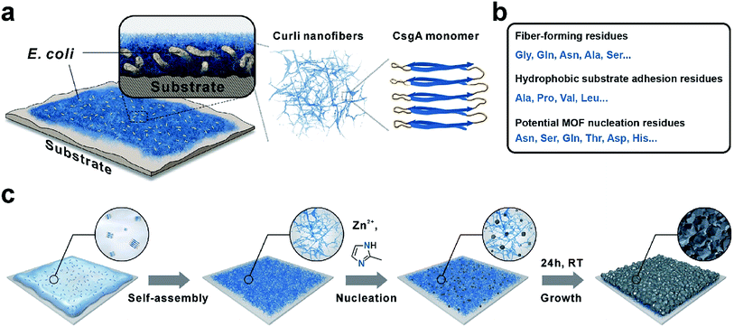
Our technical platform was essentially inspired by E. coli biofilms, which exhibit strong adhesion towards diverse biotic or abiotic interfaces and shield the living bacteria against antibiotics and chemicals with robust extracellular substances.33 In particular, curli nanofiber networks, major protein components of E. coli biofilms, contribute to the adhesion and integrity of biofilms.34 CNFs are formed via extracellular self-assembly of CsgA proteins, which themselves are composed of five repeating strand-loop-strand motifs (Scheme 1a). Each repeating unit is composed of conserved glycine, glutamine and asparagine residues. The glutamine and asparagine residues are predicted to form a hydrogen bonding network that contributes to the self-assembly and extreme stability of these fibers.34 Moreover, the hydrophobic amino acids such as alanine, proline and valine endow CNFs with strong adhesion towards hydrophobic surfaces.35 In addition, residual polar functional groups such as asparagine, serine, glutamine, tyrosine, aspartic acid and histidine, rich in –COOH, –OH, –NH2, and imidazole groups, may provide potential nucleation sites for MOF crystallization (Scheme 1b). Recently, CNFs have been harvested as organic templates for anchoring various nanomaterials and macromolecules including quantum dots, metal nanoparticles and enzymes.36–39 Finally, similar to other amyloid structures, CNFs are well known for their strong mechanical properties and high chemical/thermal stability.40 Based on these attributes, we rationalize that adhesive CNFs might serve as universal coatings to mediate the nucleation and growth of MOF materials on diverse substrates.
Results and discussion
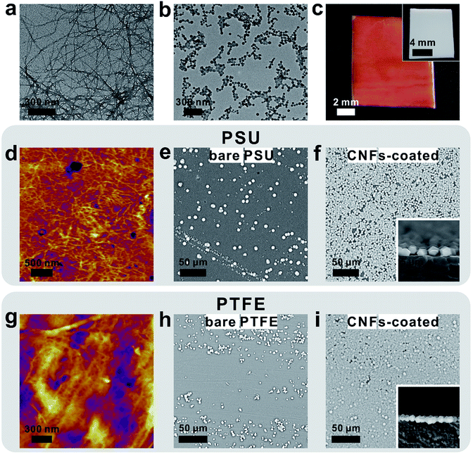
As a general procedure to apply curli nanofiber coatings, the targeting substrate was immersed in a CsgA protein buffer solution for a given amount of time to allow the self-assembly and deposition of CNFs on the substrate surface. Using this method, we first deposited CNFs onto a transmission electron microscopy (TEM) grid. The TEM image clearly showed that the self-assembly of CsgA protein led to the formation of curli nanofiber networks (Fig. 1a). Next, ZIF-8 was selected as a model system to study the feasibility of using CNFs as nucleation centers for MOF growth. After 10 min growth in a methanolic solution of Zn(NO3)2·6H2O and 2-methylimidazole (HMIM) on a CNF-coated TEM grid at room temperature, sub-100 nm ZIF-8 particles emerged and interconnected into a fibrous network suggesting that the nucleation process of ZIF-8 was guided by CNFs (Fig. 1b). To monitor the early growth process of ZIF-8, atomic force microscopy (AFM) images were taken after 10, 30 and 60 min growth of ZIF-8 on a CNF-coated silicon substrate. Fig. S1a† clearly shows the formation of a fibrous network composed of ZIF-8 nanoparticles after 10 min reaction. At 30 min, more ZIF-8 particles started to emerge (Fig. S1b†). Meanwhile, the fibrous morphology became less evident. Further extending the growth period to 60 min led to the formation of larger ZIF-8 particles and disappearance of ZIF-8 nanoparticles (Fig. S1c†) due to Ostwald ripening. Both TEM and AFM results suggest that the nucleation of ZIF-8 did occur preferentially on CNFs.Next, polytetrafluoroethylene (PTFE), widely recognized as a superb non-stick substrate, was selected as the first representative example to evaluate the adhesion capability of CNFs. After immersing PTFE in freshly made CsgA/buffer solution for 24 h, a red dye, Congo red, was applied to specifically stain CNFs. Fig. 1c shows that the surface of CNF-coated PTFE (denoted as CNFs-PTFE) displays a uniform red color whereas the bare PTFE is unable to be stained (inset in Fig. 1c). This indicates that the PTFE surface can be completely and uniformly covered by CNFs on a macroscopic scale. X-ray photoelectron spectroscopy (XPS) was performed to analyze the surface composition of CNFs-PTFE. A peak at ∼400 eV (Fig. S2b†) corresponding to the 1s orbital of amide nitrogen was observed confirming the presence of CsgA proteins on the PTFE substrate. AFM images of CNF-coated PTFE and polysulfone (PSU) revealed interconnected networks of CNFs (Fig. 1d and g) in agreement with TEM observation (Fig. 1a).
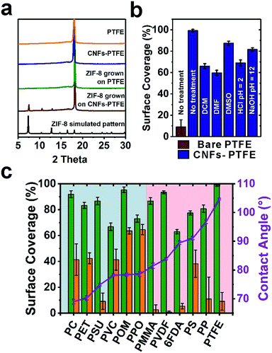
We next turned to evaluate the effectiveness of CNFs in assisting the nucleation and growth of ZIF-8 on PTFE and PSU. CNFs-PTFE and CNFs-PSU were again submerged in methanolic solutions, supplemented with Zn(NO3)2·6H2O, HMIM and 1-methylimidazole at room temperature for 24 h. Scanning electron microscopy (SEM) images revealed that ZIF-8 microcrystals with an average size of ∼3 μm were uniformly grown on both substrates with a surface coverage of 87 ± 3% and 99 ± 1% respectively (Fig. 1f, i and 2c). In contrast, only 9 ± 6% and 9 ± 7% of surfaces were found to be covered by ZIF-8 for bare PSU and PTFE substrates under the same growth conditions (Fig. 1e, h and 2c). Cross-section SEM images showed that the ZIF-8 coatings were composed of a single layer of ZIF-8 crystallites with good continuity (insets in Fig. 1f and i). Powder X-ray diffraction (PXRD) patterns confirmed that the particles grown on PTFE and CNFs-PTFE were indeed ZIF-8 (Fig. 2a). However, the diffraction intensity of ZIF-8 crystals on bare PTFE was significantly weaker than that of the crystals grown on CNFs-PTFE apparently due to less surface coverage, as indicated by the SEM results (Fig. 1e and h).
To evaluate the universality of this approach, we further applied this method to nine additional commercially available polymeric substrates: polycarbonate (PC), polyethylene terephthalate (PET), polyvinyl chloride (PVC), polyoxymethylene (POM), poly(p-phenylene oxide) (PPO), poly(methyl methacrylate) (PMMA), microporous PVDF, polystyrene (PS), polypropylene (PP), and one as-synthesized polyimide, 4,4′-(hexafluoroisopropylidene)diphthalic anhydride (6FDA)–2,4,6-trimethyl-1,3-phenylenediamine (DAM). After forming curli nanofiber coatings, a decrease in the water contact angle was observed for all 12 substrates (Fig. S16†), as a quick indication of the successful surface modification by CNFs. Fig. 2c shows the statistical analysis of ZIF-8 coverage on all 12 substrates with and without curli nanofiber coatings. For non-coated substrates, six relatively more hydrophilic ones (highlighted in the blue region, Fig. 2c) were relatively easy for ZIF-8 to grow achieving medium ZIF-8 coverage from 41% to 65%. One exception was PSU which only achieves 9 ± 6% coverage by ZIF-8. The more hydrophobic substrates, however, only had 0.9% to 11% ZIF-8 coverage with PS performing slightly better (38% coverage). In contrast, for CNF-coated substrates, significantly improved ZIF-8 coverage in the range from 63% to 99% was observed in all cases. Microporous PVDF, as the most extreme case, exhibited a boost of ZIF-8 coverage from 0.9 ± 0.8% to 93 ± 1%, a striking two orders of magnitude improvement. Moreover, ZIF-8 grown on CNF-coated surfaces also exhibited more even particle distribution than on bare substrates, as revealed by the significantly smaller error bars (Fig. 2c).
One prominent feature of CNFs is their high chemical and thermal stability towards harsh conditions owing to the strong hydrogen bonding networks. To assess the robustness and stability of curli nanofiber coatings on substrates in the presence of organic solvents, strong acids and strong bases, we treated five CNFs-PTFE samples with dichloromethane (DCM), dimethylformamide (DMF), dimethyl sulfone (DMSO), HCl solution (pH = 2), and NaOH solution (pH = 12) for 48 h, respectively, before ZIF-8 growth. As a result, ZIF-8 coverage of 66 ± 2%, 60 ± 2%, 88 ± 2%, 69 ± 3% and 82 ± 2% was obtained for each sample, respectively (Fig. 2b). Despite some variation, these coverage values are still considerably higher than that of the bare PTFE substrate, demonstrating the robustness of this methodology towards aggressive chemical environments.
To further evaluate the mechanical stability of CNF mediated ZIF-8 coatings, adhesive tape peel tests were performed on three ZIF-8 coated PS substrates. After one cycle of tape peel test using a standard high-tack tape (VHB, 3M, with an adhesion to steel value of 2600 N m−1), micron-sized ZIF-8 particles were completely removed from the CNF-coated PS surface as shown in Fig. S18a and b.† However, sub-100 nm ZIF-8 particles grown on CNF-coated PS were significantly more resistant to mechanical peeling as most of the area on PS remained covered by ZIF-8 (Fig. S18c and d†) after one peeling cycle. In contrast, ZIF-8 particles gown on bare PS surfaces were completely removed by the adhesive tape (Fig. S18e and f†) suggesting that the mechanical stability of ZIF-8 coatings benefits tremendously from the adhesion of CNFs. However, such an effect becomes less evident when the particle size increases.
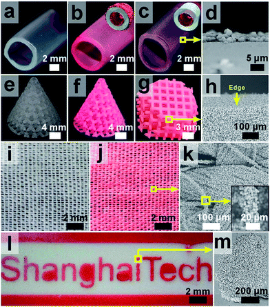
Next, we investigated whether this method is suitable for ZIF-8 growth on complex-shaped objects or patterned surfaces with spatial control. To facilitate the visualization of the macroscopic distribution of ZIF-8 particles on different subjects, a red dye, new coccine, was added to the growth solution to incorporate into ZIF-8 crystals during growth so that the crystals displayed a vivid red color. We first tested ZIF-8 growth with three identical pieces of perfluoroalkoxy alkane (PFA) tubing, with tube surfaces fully (tube #2, Fig. 3b), partially (tube #3, Fig. 3c) or not (tube #1, Fig. 3a) coated with CNFs. After an identical growth period, both the interior and exterior of tube #2 were coated with a layer of ZIF-8 crystals (Fig. 3b). On tube #3, ZIF-8 was only found on the inner wall, on which CNFs were selectively deposited (Fig. 3c). In contrast, ZIF-8 crystals failed to grow on the surface of tube #1 (Fig. 3a), suggesting that the CNF modification is critical for the mineralization of ZIF-8 to occur on PFA surfaces. When a 3D printed photosensitive resin (PR) pyramid scaffold was applied for ZIF-8 growth, complete coverage of ZIF-8 particles was found from the exterior to the very interior of the object despite its complex geometry (Fig. 3f–h). When this practice was applied on a piece of woven PET fabric, ZIF-8 particles were again observed on every single fiber across the whole fabric (Fig. 3j and k). Note that without curli nanofiber coatings, only very low ZIF-8 coverage was achieved (Fig. S19 and S20†). By applying a mask to restrict the deposition of CNFs only to the exposed area on PTFE, we successfully fabricated a “ShanghaiTech” university logo comprising ZIF-8 particles with good fidelity and sharp contrast (Fig. 3l and m). Collectively, these results suggested that our approach for ZIF-8 growth could be widely applicable to a variety of polymeric substrates with diverse surface chemistry and geometry.
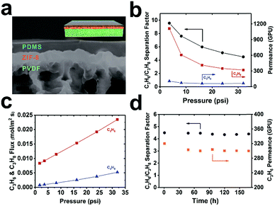
To further illustrate its potential application, we exploited this method for the fabrication of MOF-based TFC membranes for propylene/propane separation. Industrial propylene/propane separation using cryogenic distillation is an extremely energy intensive process. Membrane-based separation is regarded as an attractive alternative to surmount this challenge.41 Recently, ZIF-8 membranes showed exceptionally high performance for propane/propylene separation.15,42 Moreover, MOF membranes, in general, are more resilient to plasticization owing to their structural rigidity. Therefore, they are expected to have higher operation stability than their polymeric counterparts. However, one major roadblock for the industrial deployment of pure MOF membranes is the lack of a reliable and scalable fabrication method for growing a thin yet defect-free layer of MOF on porous polymeric supports.43–45 One unique aspect of curli nanofiber-mediated MOF growth is that while it provides a macroscopically uniform nucleation layer for MOF growth, the loose fibrous network also creates openings for the passage of gases hence maintaining the flux. As a proof-of-concept, we successfully fabricated ZIF-8@CNFs-PVDF TFC membranes through a three-step process. First, ZIF-8 microcrystals were uniformly grown on a curli nanofiber-mediated PVDF microporous membrane with a surface coverage of ∼93% (Fig. S12†). Next, a layer-by-layer technique developed by Tanaka et al.46 was applied to seal the remaining gaps (Fig. S21a,† high-resolution SEM image). Finally, a PDMS gutter layer was applied on top of ZIF-8 to further seal off the pinholes (Fig. S21b,† high-resolution SEM image). The cross-section SEM image showed that a 760 ± 80 nm ZIF-8 layer was uniformly and seamlessly grown on the microporous PVDF substrate covered by an ∼1 μm PDMS skin layer (Fig. 4a). No apparent pinholes were observed on the ZIF-8 layer (Fig. S21b†). A mixed-gas transport experiment was performed with an equimolar binary C3H6/C3H8 feed using a constant pressure set-up (Fig. S22†). Pressure dependent permeation data showed that under low transmembrane pressure (TMP, 3.6 psi), C3H6 and C3H8 permeances of 1110 and 116 GPU were recorded (1 GPU = 3.35 × 10⁻¹⁰ mol m−2 s−1 Pa−1), respectively, leading to a separation factor of 10. With increasing TMP, the permeance of C3H6 gradually decreased eventually reaching 320 GPU at 32 psi. Similar behavior was also observed by Nair et al.43 which is associated with the increasing saturation of adsorption sites in ZIF-8. The permeance of C3H8 only exhibited a small drop from 116 GPU at 3.6 psi to 71 GPU at 32 psi, resulting in a separation factor of 4.5 at 32 psi (Fig. 4b). Such gas transport trends suggest that defects in this TFC membrane are insignificant as otherwise, we would expect a dramatic increase of permeance with increasing feed pressure due to the presence of pinholes. Despite the relatively low separation factor, the thin nature of the ZIF-8 selective layer contributed to a very high C3H6 permeance (1110 GPU at 3.6 psi and 320 GPU at 32 psi) which is a desirable feature in a real industrial setting. Despite the decrease of C3H6 permeance with increasing TMP, the flux increased linearly within the tested pressure range, leading to a 2.8-fold increase in flux at 32 psi as compared to operation at 3.6 psi (Fig. 4c). To more rigorously evaluate the reproducibility of the membrane separation performance, we further tested 5 additional membrane samples. The average permeances of C3H6 and C3H8 and selectivity at ∼3.6 psi were 1044 ± 131 GPU, 104 ± 35 GPU and 11 ± 4 respectively (Fig. S23†) indicating good reproducibility. We tested the operation stability of the membrane at 32 psi TMP with an equimolar binary C3H6/C3H8 feed up to 7 days. No apparent decrease of either the permeance or separation factor was observed suggesting the high robustness of this ZIF-8 membrane for C3H6/C3H8 separation (Fig. 4d).
Notably, this technique platform is not limited to a specific type of MOF. Given its high chemical and thermal stability, this method should also be applicable to the fabrication of MOF membranes requiring high heat and aggressive organic solvents during synthesis. As a preliminary demonstration, a thin film of a zirconium MOF, UiO-66,47 was grown onto CNFs-PTFE. The synthesis was carried out at 120 °C in dimethylformamide (DMF) with the addition of acetic acid as a modulator. The SEM image showed a uniform layer of UiO-66 crystallites with 88 ± 2% surface coverage (Fig. S24a†). Investigation of such a membrane for gas separation is underway.
Conclusions
We demonstrated a new technique platform that leverages adhesive CNFs as universal coatings on diverse polymeric substrates or objects with complex geometries to mediate controlled growth of MOF materials. As a result, significantly improved MOF surface coverage was achieved on CNF-coated substrates as compared to that of bare substrates. Further extending this strategy led to the successful growth of ZIF-8 on PFA tubing, 3D printed PR pyramid scaffolds, and PET fabrics. By pre-patterning the PTFE surface with CNFs, a corresponding ZIF-8 pattern replica was obtained with good fidelity and high contrast. Transferring this technology to membrane fabrication afforded a 760 nm ZIF-8 TFC membrane which showed a C3H6/C3H8 mixed-gas separation factor up to 10, C3H6 permeance up to 1110 GPU and operational stability up to 7 days. We believe that this method will serve as a general route for mediating the interfaces between MOFs and polymers, thus paving the way towards the development of more sophisticated MOF membranes and devices.Conflicts of interest
There are no conflicts to declare.Acknowledgements
This work was partially supported by the Shanghai Pujiang Program, China (Grant No. 16PJ1406700), the National Natural Science Foundation of China (Grant No. 21701110) and the start-up funding from ShanghaiTech University for T. L. This work was partially sponsored by the Commission for Science and Technology of Shanghai Municipality (Grant No. 17JC1403900), the “Dawn” Program of Shanghai Education Commission, China (Grant No. 14SG56), the Joint Funds of the National Natural Science Foundation of China (Seed Grant No. U1532127), and the National Natural Science Foundation of China (Grant No. 31570972) for C. Z. This work made use of the resources of the Instrumental Analysis Center and the Centre for High-resolution Electron Microscopy in ShanghaiTech.Notes and references
- N. L. Rosi, J. Eckert, M. Eddaoudi, D. T. Vodak, J. Kim, M. O'Keeffe and O. M. Yaghi, Science, 2003, 300, 1127–1129 CrossRef PubMed.
- K. Sumida, D. L. Rogow, J. A. Mason, T. M. McDonald, E. D. Bloch, Z. R. Herm, T. H. Bae and J. R. Long, Chem. Rev., 2012, 112, 724–781 CrossRef PubMed.
- H. C. Zhou and S. Kitagawa, Chem. Soc. Rev., 2014, 43, 5415–5418 RSC.
- Q. Yang, Q. Xu and H. L. Jiang, Chem. Soc. Rev., 2017, 46, 4774–4808 RSC.
- P. Horcajada, R. Gref, T. Baati, P. K. Allan, G. Maurin, P. Couvreur, G. Ferey, R. E. Morris and C. Serre, Chem. Rev., 2012, 112, 1232–1268 CrossRef PubMed.
- H. Guo, G. Zhu, I. J. Hewitt and S. Qiu, J. Am. Chem. Soc., 2009, 131, 1646–1647 CrossRef PubMed.
- G. Lu, O. K. Farha, W. Zhang, F. Huo and J. T. Hupp, Adv. Mater., 2012, 24, 3970–3974 CrossRef PubMed.
- A. J. Brown, N. A. Brunelli, K. Eum, F. Rashidi, J. R. Johnson, W. J. Koros, C. W. Jones and S. Nair, Science, 2014, 345, 72–75 CrossRef PubMed.
- S. Qiu, M. Xue and G. Zhu, Chem. Soc. Rev., 2014, 43, 6116–6140 RSC.
- Y. Zhang, S. Yuan, X. Feng, H. Li, J. Zhou and B. Wang, J. Am. Chem. Soc., 2016, 138, 5785–5788 CrossRef PubMed.
- L. E. Kreno, K. Leong, O. K. Farha, M. Allendorf, R. P. Van Duyne and J. T. Hupp, Chem. Rev., 2012, 112, 1105–1125 CrossRef PubMed.
- O. Shekhah, H. Wang, S. Kowarik, F. Schreiber, M. Paulus, M. Tolan, C. Sternemann, F. Evers, D. Zacher, R. A. Fischer and C. Woll, J. Am. Chem. Soc., 2007, 129, 15118–15119 CrossRef PubMed.
- E. Biemmi, C. Scherb and T. Bein, J. Am. Chem. Soc., 2007, 129, 8054–8055 CrossRef PubMed.
- Q. Liu, N. Wang, J. Caro and A. Huang, J. Am. Chem. Soc., 2013, 135, 17679–17682 CrossRef PubMed.
- G. He, M. Dakhchoune, J. Zhao, S. Huang and K. V. Agrawal, Adv. Funct. Mater., 2018, 1707427, DOI:10.1002/adfm.201707427.
- R. Ameloot, L. Stappers, J. Fransaer, L. Alaerts, B. F. Sels and D. E. De Vos, Chem. Mater., 2009, 21, 2580–2582 CrossRef.
- X. Zou, G. Zhu, I. J. Hewitt, F. Sun and S. Qiu, Dalton Trans., 2009, 3009–3013, 10.1039/b822248g.
- S. Hermes, F. Schroder, R. Chelmowski, C. Woll and R. A. Fischer, J. Am. Chem. Soc., 2005, 127, 13744–13745 CrossRef PubMed.
- G. Huang, D. M. Yin and L. M. Wang, J. Mater. Chem. A, 2016, 4, 15106–15116 Search PubMed.
- Y. Yoo and H. K. Jeong, Chem. Commun., 2008, 2441–2443, 10.1039/b800061a.
- S. M. Yoon, J. H. Park and B. A. Grzybowski, Angew. Chem., Int. Ed., 2017, 56, 127–132 CrossRef PubMed.
- S. Zhang, Z. Wang, H. Ren, F. Zhang and J. Jin, J. Mater. Chem. A, 2017, 5, 1962–1966 Search PubMed.
- E. Barankova, X. Tan, L. F. Villalobos, E. Litwiller and K. V. Peinemann, Angew. Chem., Int. Ed., 2017, 56, 2965–2968 CrossRef PubMed.
- M. Meilikhov, K. Yusenko, E. Schollmeyer, C. Mayer, H. J. Buschmann and R. A. Fischer, Dalton Trans., 2011, 40, 4838–4841 RSC.
- Y. Chen, S. Zhang, S. Cao, S. Li, F. Chen, S. Yuan, C. Xu, J. Zhou, X. Feng, X. Ma and B. Wang, Adv. Mater., 2017, 29, 1606221 CrossRef PubMed.
- P. Falcaro, A. J. Hill, K. M. Nairn, J. Jasieniak, J. I. Mardel, T. J. Bastow, S. C. Mayo, M. Gimona, D. Gomez, H. J. Whitfield, R. Ricco, A. Patelli, B. Marmiroli, H. Amenitsch, T. Colson, L. Villanova and D. Buso, Nat. Commun., 2011, 2, 237 CrossRef PubMed.
- S. M. Meckler, C. Li, W. L. Queen, T. E. Williams, J. R. Long, R. Buonsanti, D. J. Milliron and B. A. Helms, Chem. Mater., 2015, 27, 7673–7679 CrossRef.
- M. Zhou, J. Li, M. Zhang, H. Wang, Y. Lan, Y. N. Wu, F. Li and G. Li, Chem. Commun., 2015, 51, 2706–2709 RSC.
- C. T. He, L. Jiang, Z. M. Ye, R. Krishna, Z. S. Zhong, P. Q. Liao, J. Xu, G. Ouyang, J. P. Zhang and X. M. Chen, J. Am. Chem. Soc., 2015, 137, 7217–7223 CrossRef PubMed.
- K. Liang, C. Carbonell, M. J. Styles, R. Ricco, J. Cui, J. J. Richardson, D. Maspoch, F. Caruso and P. Falcaro, Adv. Mater., 2015, 27, 7293–7298 CrossRef PubMed.
- K. S. Park, Z. Ni, A. P. Cote, J. Y. Choi, R. Huang, F. J. Uribe-Romo, H. K. Chae, M. O'Keeffe and O. M. Yaghi, Proc. Natl. Acad. Sci. U. S. A., 2006, 103, 10186–10191 CrossRef PubMed.
- X. C. Huang, Y. Y. Lin, J. P. Zhang and X. M. Chen, Angew. Chem., Int. Ed., 2006, 45, 1557–1559 CrossRef PubMed.
- H. C. Flemming and J. Wingender, Nat. Rev. Microbiol., 2010, 8, 623–633 CrossRef PubMed.
- M. M. Barnhart and M. R. Chapman, Annu. Rev. Microbiol., 2006, 60, 131–147 CrossRef PubMed.
- E. P. DeBenedictis, J. Liu and S. Keten, Sci. Adv., 2016, 2, e1600998 Search PubMed.
- X. Wang, J. Pu, B. An, Y. Li, Y. Shang, Z. Ning, Y. Liu, F. Ba, J. Zhang and C. Zhong, Adv. Mater., 2018, 30, 1705968 CrossRef PubMed.
- C. Zhong, T. Gurry, A. A. Cheng, J. Downey, Z. Deng, C. M. Stultz and T. K. Lu, Nat. Nanotechnol., 2014, 9, 858–866 CrossRef PubMed.
- B. An, X. Wang, M. Cui, X. Gui, X. Mao, Y. Liu, K. Li, C. Chu, J. Pu, S. Ren, Y. Wang, G. Zhong, T. K. Lu, C. Liu and C. Zhong, ACS Nano, 2017, 11, 6985–6995 CrossRef PubMed.
- L. Jiang, X. Song, Y. Li, Q. Xu, J. Pu, H. Huang and C. Zhong, ACS Catal., 2018, 8, 1837–1842 CrossRef.
- T. P. Knowles and M. J. Buehler, Nat. Nanotechnol., 2011, 6, 469–479 CrossRef PubMed.
- K. Eum, A. Rownaghi, D. Choi, R. R. Bhave, C. W. Jones and S. Nair, Adv. Funct. Mater., 2016, 26, 5011–5018 CrossRef.
- W. Li, P. Su, Z. Li, Z. Xu, F. Wang, H. Ou, J. Zhang, G. Zhang and E. Zeng, Nat. Commun., 2017, 8, 406 CrossRef PubMed.
- K. Eum, C. Ma, A. Rownaghi, C. W. Jones and S. Nair, ACS Appl. Mater. Interfaces, 2016, 8, 25337–25342 Search PubMed.
- E. Shamsaei, X. Lin, Z. X. Low, Z. Abbasi, Y. Hu, J. Z. Liu and H. Wang, ACS Appl. Mater. Interfaces, 2016, 8, 6236–6244 Search PubMed.
- H. T. Kwon and H. K. Jeong, J. Am. Chem. Soc., 2013, 135, 10763–10768 CrossRef PubMed.
- K. Kida, K. Fujita, T. Shimada, S. Tanaka and Y. Miyake, Dalton Trans., 2013, 42, 11128–11135 RSC.
- J. H. Cavka, S. Jakobsen, U. Olsbye, N. Guillou, C. Lamberti, S. Bordiga and K. P. Lillerud, J. Am. Chem. Soc., 2008, 130, 13850–13851 CrossRef PubMed.
Footnotes |
| † Electronic supplementary information (ESI) available. See DOI: 10.1039/c8sc01591k |
| ‡ These authors contributed equally. |
| This journal is © The Royal Society of Chemistry 2018 |

