 Open Access Article
Rechargeable aluminum–selenium batteries with high capacity†
Xiaodan
Huang
 ,
Yang
Liu
,
Chao
Liu
,
Jun
Zhang
,
Owen
Noonan
and
Chengzhong
Yu
,
Yang
Liu
,
Chao
Liu
,
Jun
Zhang
,
Owen
Noonan
and
Chengzhong
Yu
 *
*
Australian Institute for Bioengineering and Nanotechnology, The University of Queensland, Brisbane QLD 4072, Australia. E-mail: c.yu@uq.edu.au
First published on 17th May 2018
Abstract
Rechargeable aluminum (Al) batteries are emerging as a promising post lithium-ion battery technology. Herein, we demonstrate a conceptually new design of rechargeable aluminum–selenium (Al–Se) batteries by understanding the selenium chemistry and controlling the electrode reaction. The Al–Se battery consists of a composite cathode including selenium nanowires and mesoporous carbon (CMK-3) nanorods, an Al metal anode and chloroaluminate ionic liquid electrolyte. The working mechanism of the Al–Se battery is the reversible redox reaction of the Se2Cl2/Se pair confined in the mesopores of CMK-3 nanorods. Al–Se batteries deliver a high reversible capacity of 178 mA h g−1 (by Se mass), high discharge voltages (mainly above 1.5 V), and good cycling/rate performances.
Introduction
Developing next-generation rechargeable batteries with high energy density, low cost, and improved safety is essential for a sustainable energy future.1 Rechargeable Al-ion batteries have attracted great research interest as a promising post lithium-ion battery technology due to the high theoretical capacity (2980 mA h g−1 and 8040 mA h cm−3), high natural abundance and high safety profile of Al.1b The major challenge for the development of Al-ion batteries lies in the cathode. A broad range of cathode materials including metal oxides,2 metal sulfides,3 MXenes,4 conductive polymers,5 and microporous carbon6 have been investigated, but show relatively low discharge potential (<1.0 V),2–7 low discharge capacity2c,3b,4,7 or capacitive behaviors.5,6 Graphitic carbon materials are currently the most promising cathodes, presenting a high discharge voltage and long cycle life.8 However, their charge storage capabilities are limited by their inherent intercalation mechanism with relatively low specific capacities between 60 and 150 mA h g−1.Inspired by the progress in lithium–sulfur battery technology, rechargeable Al–S batteries have also been developed very recently.9 This type of battery is based on the reversible reduction of S in chloroaluminate ionic liquids (S + e− ⇄ Al2S3), which provides a high theoretical capacity (1072 mA g−1 by S mass) and a theoretical voltage of 1.23 V. However, in experimental tests, prototype Al–S batteries can only exhibit long low-voltage discharge plateaus (∼0.95 V) and very fast capacity decay within ∼20 cycles, owing to the sluggish kinetics of the battery reactions and the consequent severe polarization.9 Therefore, it remains challenging to explore new battery chemistry for rechargeable Al batteries with the potential to deliver high voltage, high capacity and good cycling stability.
Se, a chemical analogue of S, has been extensively investigated as an active cathode in rechargeable lithium and sodium electrochemical systems.10 Se has similar electrochemical properties to S, but slightly lower ionization potentials (e.g. 1st ionization: 9.7 vs. 10.4 eV), which enables a relatively easier electrochemical oxidation process of the Se element than S.11 Besides, the much higher electrical conductivity of Se over S (1 × 10⁻³vs. 0.5 × 10⁻²⁷ S m−1) is another important merit for its use in rechargeable batteries with improved properties. Early research on the electrochemical behaviors of Se in chloroaluminate molten salts (AlCl3/NaCl) has shown that Se can be reversibly oxidized to stable oxidative states,11 suggesting the potential application of Se as a cathode material in rechargeable Al batteries. However, until now, there is no report of using Se cathodes in rechargeable Al batteries. Analysis of literature findings indicates that the typical oxidation product of Se in chloroaluminate electrolytes, Se2Cl2,11c,d is an oily liquid (melting point of −85 °C).12 Thus, if only Se is used in the cathode, Se2Cl2 formed during the charging process will easily diffuse in electrolytes (Fig. S1†), which causes cell failure.
Understanding the selenium chemistry and the properties of Se2Cl2 holds promise to solve this problem. Despite its high dipole moment, early studies have revealed that Se2Cl2 has a hydrophobic nature, which is insoluble in water or concentrated sulfuric acid, but miscible with aromatic hydrocarbons such as benzene and toluene.12 In our screen tests, CMK-3 nanorods,13 a high surface area mesoporous carbon, showed fast adsorption towards the reddish charged product of a pure Se cathode (Fig. S1†), suggesting that Se2Cl2 can be adsorbed into CMK-3 through hydrophobic interactions to form a stable cathode. With this finding, here we present the first report of a rechargeable Al–Se battery in a chloroaluminate ionic liquid electrolyte, using Se nanowires and CMK-3 nanorods as the composite cathode while Al foil as the anode (Fig. 1a). CMK-3 nanorods act as the reservoir to capture Se2Cl2 that is generated in the charging step in situ. Subsequently, the reversible cathode reaction of the Se2Cl2/Se pair occurs in the confined mesopores of CMK-3, which prevents the leaching of the charged product (Se2Cl2) and improves the battery performance. Our designed Al–Se batteries deliver high discharge voltages (mainly above 1.5 V), high reversible capacity (178 mA h g−1 at 100 mA g−1, by Se mass), good cycling stability (82% retention over 50 cycles), and reasonable rate performance.
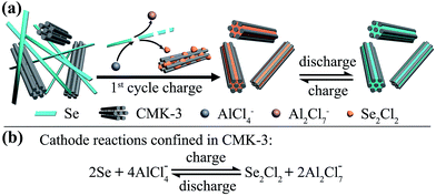 | ||
| Fig. 1 (a) Schematic illustration of the proposed mechanism for Al–Se batteries using Se nanowires and CMK-3 composite cathodes. (b) The proposed reversible reaction of the Se cathode. | ||
Results and discussion
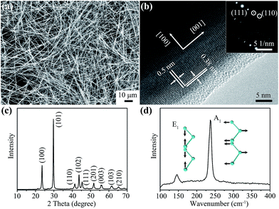
The Se nanowires were prepared by a low temperature hydrothermal synthesis (see experimental procedures in the ESI†). The morphology of the prepared material was examined by scanning electron microscopy (SEM) and transmission electron microscopy (TEM). The low-magnification SEM image (Fig. 2a) shows that this material consists of one dimensional nanowires with an ultra-high aspect ratio. The length of Se nanowires can be tens of microns and their width about 200 nm as shown in the magnified SEM image and TEM images (Fig. S2†). The crystallinity of the nanowires was demonstrated by high-resolution TEM (HR-TEM) and selected area electron diffraction (SAED) analyses. Lattice fringes with spacings of 0.5 and 0.38 nm can be clearly observed in the HR-TEM image (Fig. 2b), agreeing well with the interplanar distances of the (001) and (100) planes of trigonal Se.14 The SAED pattern obtained from the nanowires can be indexed to the trigonal Se lattices of (111) and (110), respectively (Fig. 2b inset), suggesting a well crystallized structure. The crystalline phase of Se nanowires was identified by wide-angle X-ray diffraction (XRD) and Raman spectroscopy characterizations. Fig. 2c shows the XRD pattern of the prepared nanowires. All diffraction peaks can be indexed to trigonal phase Se (JCPDS no. 73-0465).15 The Raman spectrum of Se nanowires (Fig. 2d) exhibits two resonance peaks located at 143 and 237 cm−1, which are related to the E1 and A1 vibration modes of trigonal Se (Fig. 2d inset), respectively.16The demonstration of rechargeable Al–Se batteries was performed in the corrosion resistant coin-cell configuration recently developed by our group (Fig. S3†).17 Se nanowires were blended with CMK-3 nanorods (weight ratio of 2![[thin space (1/6-em)]](https://www.rsc.org/images/entities/char_2009.gif) :
:![[thin space (1/6-em)]](https://www.rsc.org/images/entities/char_2009.gif) 1), and cast on carbon cloth substrates with carbon black and Nafion binder (see experimental procedures in the ESI†). The CMK-3 carbon nanorods13 used here possess an ordered two-dimensional hexagonal mesoporous structure with a high surface area of 1632 m2 g−1, a large pore volume of 1.78 cm3 g−1 and a uniform pore size of 3.4 nm (Fig. S4†). The electrochemical properties of Al–Se batteries were first analyzed by cyclic voltammetry (CV) measurements at different scan rates (0.1 to 2.0 mV s−1). As shown in Fig. S5a,† the CV curves of Al–Se cells show two broad anodic peaks at ∼1.8 V and ∼2.25 V, which are associated with the oxidation of Se. The following reduction of Se species gives two cathodic peaks in the voltage range from 1.7 to 1.3 V. Analyzing the CV scanning results (peak current i and scan rate v) using the power law equation
1), and cast on carbon cloth substrates with carbon black and Nafion binder (see experimental procedures in the ESI†). The CMK-3 carbon nanorods13 used here possess an ordered two-dimensional hexagonal mesoporous structure with a high surface area of 1632 m2 g−1, a large pore volume of 1.78 cm3 g−1 and a uniform pore size of 3.4 nm (Fig. S4†). The electrochemical properties of Al–Se batteries were first analyzed by cyclic voltammetry (CV) measurements at different scan rates (0.1 to 2.0 mV s−1). As shown in Fig. S5a,† the CV curves of Al–Se cells show two broad anodic peaks at ∼1.8 V and ∼2.25 V, which are associated with the oxidation of Se. The following reduction of Se species gives two cathodic peaks in the voltage range from 1.7 to 1.3 V. Analyzing the CV scanning results (peak current i and scan rate v) using the power law equation
| i = a × vb |
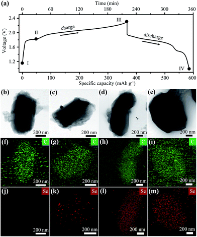
The first cycle galvanostatic charge–discharge profile of the Se nanowires/CMK-3 composite in Al–Se cells is shown in Fig. 3a. The charge branch exhibits a long voltage plateau between ∼1.8 and 2.3 V with a capacity of 352 mA h g−1. According to Faraday's law, the theoretical capacity of the Se cathode can be calculated using the equation
| Co = nF/3.6M. |
![[thin space (1/6-em)]](https://www.rsc.org/images/entities/char_2009.gif) 485.3329 s A mol−1), and M is the molecular weight of Se (78.97 g mol−1). When Se(0) is oxidized to Se(I) (i.e. n = 1), it can deliver a theoretical capacity of about 339 mA h g−1. Comparing this to the practical first charge capacity, it is hypothesized that the major valence state of Se in the charge product is Se(I). In the first discharge branch, the main voltage plateau lies between ∼1.95 V and ∼1.5 V, followed by a small low-voltage discharge region, which could be related to the reduction of Se(I) to Se(0).
485.3329 s A mol−1), and M is the molecular weight of Se (78.97 g mol−1). When Se(0) is oxidized to Se(I) (i.e. n = 1), it can deliver a theoretical capacity of about 339 mA h g−1. Comparing this to the practical first charge capacity, it is hypothesized that the major valence state of Se in the charge product is Se(I). In the first discharge branch, the main voltage plateau lies between ∼1.95 V and ∼1.5 V, followed by a small low-voltage discharge region, which could be related to the reduction of Se(I) to Se(0).
The chemical state changes during the charge–discharge process were investigated by Raman spectroscopy and X-ray photoelectron spectroscopy (XPS) characterizations of Al–Se battery cathodes (Fig. 4). At the initial stage, the Raman spectrum of the cathode in the range between 100 and 400 cm−1 shows two distinct peaks at 143 and 237 cm−1, the same as the spectrum of pristine Se nanowires (Fig. 4a). When fully charged at 2.3 V, the 143 cm−1 band almost completely disappears, and the 237 cm−1 band becomes negligible, suggesting the consumption of most Se nanowires. Meanwhile, a new Raman band emerges at about 360 cm−1, which can be ascribed to the asymmetric stretching mode of Se2Cl2.18 The Raman spectrum of the Se cathode at the fully discharged stage (1.0 V) shows a broad peak centred at 253 cm−1, the characteristic peak of amorphous Se, indicating the recovery of Se(0).15b The XPS analysis results further support the variation of the Se valence during Al–Se battery operation. During cell charging (Fig. 4b(i)–(ii)), the Se3d peak shifting from 54.9 eV to higher binding energy validates an oxidizing process of trigonal Se nanowires.19 The binding energy of Se3d in this oxidized Se species is around 57.0 eV, much lower than ∼59.1 V for typical Se(IV),19b,c suggesting a moderate oxidation of Se(0) to Se(I). Meanwhile, the subsequent back-shifting of the Se3d peak to 55.6 eV (Fig. 4b(ii)–(iii)) marks the reduction of oxidized Se species to amorphous Se during discharging.15b Based on the spectroscopic characterizations and the capacity calculation, the cathode reaction is suggested in Fig. 1b with Se2Cl2 as the major charge product.
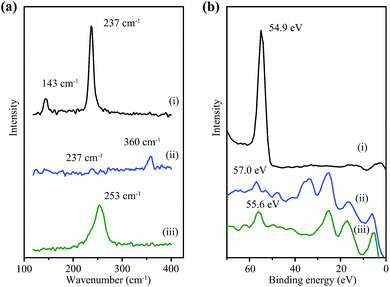 | ||
| Fig. 4 (a) Raman spectra and (b) XPS analyses of Se cathodes at different charge–discharge steps: (i) before charging, (ii) fully charged at 2.3 V, and (iii) fully discharged at 1.0 V. | ||
The morphology of the cathode during the first charge–discharge cycle was monitored by ex situ SEM and TEM characterizations. Before cell charging (stage I in Fig. 3a), the SEM image of the cathode shows a uniform mixture of long Se nanowires and rod-like CMK-3 particles (Fig. S6a†). When charged to 1.8 V (stage II), Se nanowires become short and a bit aggregated (Fig. S6b†), owing to their reaction with the electrolyte. These Se wires are nearly all disappeared at the fully charged step (III, at 2.3 V), leaving only short CMK-3 rods (Fig. S6c†), suggesting a complete reaction between Se and chloroaluminate electrolyte. A similar observation can be found in the SEM image of a fully discharged electrode (Fig. S6d,† stage IV), which implies that the electrochemical reaction of the Se2Cl2/Se pair is confined within CMK-3 mesopores.
The corresponding TEM analysis further elucidates the critical role of CMK-3 in the battery operation. At the beginning (stage I), the elemental mapping results of a typical CMK-3 particle show a carbon (C) only composition feature without Se (Fig. 3b, f and j). With the cell charging going deep (stage I and II), the concentration of Se within CMK-3 particles becomes higher (Fig. 3k and l), suggesting the capture of oily liquid Se2Cl2 by abundant mesopores during the initial charge step. After discharging to 1.0 V (stage IV, Fig. 3e, i and m), the Se concentration in the CMK-3 matrix remains at a similar level to that in the fully charged state (Fig. 3l), indicating that the Se species are confined in the mesopores. The Se cathode after 50 cycles at 100 mA g−1 was also examined, which shows a CMK-3 dominant morphology with Se encapsulated within the mesopores (Fig. S7†). It is concluded that CMK-3 mesoporous carbon with a hydrophobic nature serves as the “reservoir” to adsorb oily Se2Cl2 generated in the first charge step, and the following reversible cathode reaction occurs in the confined mesopores with good stabilities (Fig. 1).
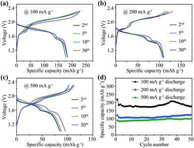
Galvanostatic charge–discharge measurement results of Se/CMK-3 composite cathodes in Al–Se batteries are shown in Fig. 5. Typical charge–discharge curves at different cycles at 100, 200 and 500 mA g−1 are presented in Fig. 5a, b and c, respectively. The profiles of these curves maintain good consistency over 30 cycles, presenting main charge voltage plateaus between ∼1.8 and 2.3 V and major discharge plateaus between ∼1.95 and 1.5 V, showing improvement over reported Al–S batteries (Table S1†).9 In comparison with the first cycle charge–discharge profile (Fig. 3a), a slight charge voltage increase (∼0.05 V at half-capacity, Fig. S8†) was observed in the second cycle. In the first cycle, the charge process corresponds to the reaction between trigonal Se nanowires and chloroaluminate electrolyte. In the second cycle, the charge reaction occurs between the amorphous Se confined in CMK-3 and electrolyte, leading to a slight charge voltage increase. The half-capacity voltages of the discharge branches are nearly the same, because the discharge reactions are all based on the reduction of Se2Cl2 confined in CMK-3. The relatively shortened main charge and discharge plateaus at 200 and 500 mA g−1 can be attributed to the slight polarization caused by the increased charge–discharge rate. The Se nanowires deliver a high initial discharge capacity of 218 mA h g−1 at 100 mA g−1 (Fig. 5d), and show good capacity retention after 50 cycles (178 mA h g−1, 82% retention), which is higher than the capacities of graphitic carbon cathodes (Table S1†).8
When increasing the current density to 200 and 500 mA g−1, the discharge capacity decreases gradually, giving reversible capacities of 124 and 101 mA h g−1 after 50 cycles. The capacity contribution from CMK-3 was assessed by testing pure CMK-3 electrodes in the same battery configuration (Fig. S9†). Pure CMK-3 can only exhibit low capacities of 15.9, 14.1 and 7.9 mA h g−1 at 100, 200 and 500 mA g−1, respectively, which confirms that the high capacity mainly comes from Se nanowires. Besides, the Se nanowire to CMK-3 ratio of 2![[thin space (1/6-em)]](https://www.rsc.org/images/entities/char_2009.gif) :
:![[thin space (1/6-em)]](https://www.rsc.org/images/entities/char_2009.gif) 1 is also an optimized formula. A low Se content weight ratio such as 1
1 is also an optimized formula. A low Se content weight ratio such as 1![[thin space (1/6-em)]](https://www.rsc.org/images/entities/char_2009.gif) :
:![[thin space (1/6-em)]](https://www.rsc.org/images/entities/char_2009.gif) 1 will significantly bring down the active component content in the whole cathode to only ∼40%. But when a higher Se content weight ratio of 3
1 will significantly bring down the active component content in the whole cathode to only ∼40%. But when a higher Se content weight ratio of 3![[thin space (1/6-em)]](https://www.rsc.org/images/entities/char_2009.gif) :
:![[thin space (1/6-em)]](https://www.rsc.org/images/entities/char_2009.gif) 1 was used, the Al–Se cell experienced a fast capacity decay within 30 cycles (Fig. S10†), indicating the importance of using sufficient CMK-3 to capture Se2Cl2 and avoid leaching/capacity decay.
1 was used, the Al–Se cell experienced a fast capacity decay within 30 cycles (Fig. S10†), indicating the importance of using sufficient CMK-3 to capture Se2Cl2 and avoid leaching/capacity decay.
Control cathodes using pure Se nanowires are also measured to further demonstrate the importance of CMK-3 addition. A typical charge–discharge profile for the pure Se nanowire cathode at 100 mA g−1 (Fig. S11a†) shows a similar pattern to the Se/CMK-3 composite cathode, but with shortened voltage plateaus, indicating far incomplete battery reactions. At high current rates of 200 and 500 mA g−1, the charge–discharge curves display very short plateaus and large voltage gaps (Fig. S11a†), suggesting severe electrochemical polarizations. The pure Se nanowire cathodes show initial discharge capacities of 136, 47.7 and 19.4 mA h g−1 at 100, 200 and 500 mA g−1, and retain only 62.7, 47.2 and 20.8 mA h g−1 after 50 cycles (Fig. S11b†). The severe polarization, low capacity and poor stability can be ascribed to the loss of the active cathode component and the degradation of the electrolyte, both caused by Se2Cl2 leaching (Fig. S1a†), which underlines the critical role of CMK-3 mesoporous carbon in Al–Se batteries.
Conclusions
In summary, we have demonstrated the first design of a rechargeable Al–Se battery. A new strategy to stabilize the liquid charge product in Al–Se cells is introduced. By creatively using CMK-3 mesoporous carbon and Se nanowires as the composite cathode, this new rechargeable battery is powered by the reversible redox reaction of the Se2Cl2/Se pair that occurs in the confined carbon mesopores. With the assistance of CMK-3, Se nanowires can deliver a high reversible capacity of 178 mA h g−1 at 100 mA g−1 with high discharge voltage (mainly above 1.5 V) and good cycling/rate stability. The new rechargeable battery and the scientific insights obtained in this research open a new avenue for the development of high performance post lithium-ion battery technology.Conflicts of interest
The authors declare no competing financial interests.Acknowledgements
We acknowledge the financial support from the Australian Research Council and the University of Queensland. We thank the Australian National Fabrication Facility and the Australian Microscopy and Microanalysis Research Facility at the Centre for Microscopy and Microanalysis, University of Queensland.Notes and references
- (a) J. W. Choi and D. Aurbach, Nat. Rev. Mater., 2016, 1, 16013, DOI:10.1038/natrevmats; (b) G. A. Elia, K. Marquardt, K. Hoeppner, S. Fantini, R. Y. Lin, E. Knipping, W. Peters, J. F. Drillet, S. Passerini and R. Hahn, Adv. Mater., 2016, 28, 7564–7579 CrossRef PubMed; (c) S. Lee and J. Cho, Angew. Chem., Int. Ed., 2015, 54, 9452–9455 CrossRef PubMed.
- (a) N. Jayaprakash, S. K. Das and L. A. Archer, Chem. Commun., 2011, 47, 12610–12612 RSC; (b) W. Wang, B. Jiang, W. Y. Xiong, H. Sun, Z. S. Lin, L. W. Hu, J. G. Tu, J. G. Hou, H. M. Zhu and S. Q. Jiao, Sci. Rep., 2013, 3, 3383 CrossRef PubMed; (c) J. G. Tu, H. P. Lei, Z. J. Yu and S. Q. Jiao, Chem. Commun., 2018, 54, 1343–1346 RSC.
- (a) S. Wang, Z. J. Yu, J. G. Tu, J. X. Wang, D. H. Tian, Y. J. Liu and S. Q. Jiao, Adv. Energy Mater., 2016, 6, 1600137 CrossRef; (b) S. Wang, S. Q. Jiao, J. X. Wang, H. S. Chen, D. H. Tian, H. P. Lei and D. N. Fang, ACS Nano, 2017, 11, 469–477 CrossRef PubMed; (c) Y. X. Hu, B. Luo, D. L. Ye, X. B. Zhu, M. Q. Lyu and L. Z. Wang, Adv. Mater., 2017, 29, 1606132 CrossRef PubMed.
- A. VahidMohammadi, A. Hadjikhani, S. Shahbazmohamadi and M. Beidaghi, ACS Nano, 2017, 11, 11135–11144 CrossRef PubMed.
- N. S. Hudak, J. Phys. Chem. C, 2014, 118, 5203–5215 Search PubMed.
- N. P. Stadie, S. T. Wang, K. V. Kraychyk and M. V. Kovalenko, ACS Nano, 2017, 11, 1911–1919 CrossRef PubMed.
- Z. J. Yu, Z. P. Kang, Z. Q. Hu, J. H. Lu, Z. Zhou and S. Q. Jiao, Chem. Commun., 2016, 52, 10427–10430 RSC.
- (a) M. C. Lin, M. Gong, B. G. Lu, Y. P. Wu, D. Y. Wang, M. Y. Guan, M. Angell, C. X. Chen, J. Yang, B. J. Hwang and H. J. Dai, Nature, 2015, 520, 325–330 CrossRef PubMed; (b) H. B. Sun, W. Wang, Z. J. Yu, Y. Yuan, S. Wang and S. Q. Jiao, Chem. Commun., 2015, 51, 11892–11895 RSC; (c) D. Y. Wang, C. Y. Wei, M. C. Lin, C. J. Pan, H. L. Chou, H. A. Chen, M. Gong, Y. P. Wu, C. Z. Yuan, M. Angell, Y. J. Hsieh, Y. H. Chen, C. Y. Wen, C. W. Chen, B. J. Hwang, C. C. Chen and H. J. Dai, Nat. Commun., 2017, 8, 14283 CrossRef PubMed; (d) X. Z. Yu, B. Wang, D. C. Gong, Z. Xu and B. G. Lu, Adv. Mater., 2017, 29, 1604118 CrossRef PubMed; (e) H. Chen, H. Y. Xu, S. Y. Wang, T. Q. Huang, J. B. Xi, S. Y. Cai, F. Guo, Z. Xu, W. W. Gao and C. Gao, Sci. Adv., 2017, 3, eaao7233 CrossRef PubMed.
- (a) T. Gao, X. G. Li, X. W. Wang, J. K. Hu, F. D. Han, X. L. Fan, L. M. Suo, A. J. Pearse, S. B. Lee, G. W. Rubloff, K. J. Gaskell, M. Noked and C. S. Wang, Angew. Chem., Int. Ed., 2016, 55, 9898–9901 CrossRef PubMed; (b) X. W. Yu and A. Manthiram, Adv. Energy Mater., 2017, 7, 1700561 CrossRef; (c) H. C. Yang, L. C. Yin, J. Liang, Z. H. Sun, Y. Z. Wang, H. C. Li, K. He, L. P. Ma, Z. Q. Peng, S. Y. Qiu, C. H. Sun, H.-M. Cheng and F. Li, Angew. Chem., Int. Ed., 2018, 57, 1898–1902 CrossRef PubMed.
- (a) S. Xin, L. Yu, Y. You, H. P. Cong, Y. X. Yin, X. L. Du, Y. G. Guo, S. H. Yu, Y. Cui and J. B. Goodenough, Nano Lett., 2016, 16, 4560–4568 CrossRef PubMed; (b) J. Ding, H. Zhou, H. L. Zhang, T. Stephenson, Z. Li, D. Karpuzov and D. Mitlin, Energy Environ. Sci., 2017, 10, 153–165 RSC; (c) C. P. Yang, S. Xin, Y. X. Yin, H. Ye, J. Zhang and Y. G. Guo, Angew. Chem., Int. Ed., 2013, 52, 8363–8367 CrossRef PubMed.
- (a) R. Marassi, G. Mamantov and J. Q. Chambers, Inorg. Nucl. Chem. Lett., 1975, 11, 245–252 CrossRef; (b) J. Robinson and R. A. Osteryoung, J. Electrochem. Soc., 1978, 125, 1454–1460 CrossRef; (c) R. Fehrmann, N. J. Bjerrum and H. A. Andreasen, Inorg. Chem., 1975, 14, 2259–2264 CrossRef; (d) M. Matsunaga, M. Morimitsu and K. Hosokawa, J. Electrochem. Soc., 1995, 142, 2910–2913 CrossRef.
- (a) V. Lenher and C. H. Kao, J. Am. Chem. Soc., 1925, 47, 772–774 CrossRef; (b) V. Lenher and C. H. Kao, J. Am. Chem. Soc., 1926, 48, 1550–1556 CrossRef; (c) C. P. Smyth, G. L. Lewis, A. J. Grossman and F. B. Jennings, J. Am. Chem. Soc., 1940, 62, 1219–1223 CrossRef.
- (a) S. Jun, S. H. Joo, R. Ryoo, M. Kruk, M. Jaroniec, Z. Liu, T. Ohsuna and O. Terasaki, J. Am. Chem. Soc., 2000, 122, 10712–10713 CrossRef; (b) C. Z. Yu, J. Fan, B. Z. Tian, D. Y. Zhao and G. D. Stucky, Adv. Mater., 2002, 14, 1742–1745 CrossRef.
- B. Gates, B. Mayers, A. Grossman and Y. N. Xia, Adv. Mater., 2002, 14, 1749–1752 CrossRef.
- (a) B. T. Mayers, K. Liu, D. Sunderland and Y. N. Xia, Chem. Mater., 2003, 15, 3852–3858 CrossRef; (b) X. M. Zhou, P. Gao, S. C. Sun, D. Bao, Y. Wang, X. B. Li, T. T. Wu, Y. J. Chen and P. P. Yang, Chem. Mater., 2015, 27, 6730–6736 CrossRef.
- J. K. Qin, G. Qiu, J. Jian, H. Zhou, L. M. Yang, A. Charnas, D. Y. Zemlyanov, C. Y. Xu, X. F. Xu, W. Z. Wu, H. Y. Wang and P. D. D. Ye, ACS Nano, 2017, 11, 10222–10229 CrossRef PubMed.
- X. D. Huang, Y. Liu, H. W. Zhang, J. Zhang, O. Noonan and C. Z. Yu, J. Mater. Chem. A, 2017, 5, 19416–19421 Search PubMed.
- (a) W. Kiefer, Spectrochimica Acta, Part A: Molecular and Biomolecular Spectroscopy, 1971, 27, 1285–1292 CrossRef; (b) P. J. Hendra and P. J. D. Park, J. Chem. Soc. A, 1968, 908–911 RSC.
- (a) L. Cueva, K. Lauwaet, R. Otero, J. M. Gallego, C. Alonso and B. H. Juarez, J. Phys. Chem. C, 2014, 118, 4998–5004 CrossRef; (b) M. Shenasa, S. Sainkar and D. Lichtman, J. Electron Spectrosc. Relat. Phenom., 1986, 40, 329–337 CrossRef; (c) H. Rupp and U. Weser, Bioinorg. Chem., 1975, 5, 21–32 CrossRef PubMed.
Footnote |
| † Electronic supplementary information (ESI) available. See DOI: 10.1039/c8sc01054d |
| This journal is © The Royal Society of Chemistry 2018 |

