DOI:
10.1039/C7RA13125A
(Paper)
RSC Adv., 2018,
8, 6069-6074
Stable multi-jet electrospinning with high throughput using the bead structure nozzle†
Received
7th December 2017
, Accepted 19th January 2018
First published on 6th February 2018
Abstract
A modified bead structure nozzle for the electrospinning process was developed to improve the production efficiency of nanofibers and facilitate the cleaning of equipment. The effects of the flow rate, voltage and receiving distance on the number of jets were studied. The results indicate that the number of stable jets can be effectively controlled by spinning conditions. The rotating spinning phenomenon, which occurred during spinning, was subjected to force analysis. The COMSOL Multiphysics model was applied to simulate the electric field to show that the bead structured nozzle does not change the overall spinning electric field compared with traditional spinning. The results indicate that the bead structure nozzle can produce a stable multi-jet using a curved surface structure and improve the production efficiency of nanofibers. Compared with the high-voltage conditions of needleless spinning, the bead-type nozzle helps to save energy and facilitate cleaning, so as to avoid the production of waste in experimental research and industrial production.
Introduction
Electrospinning has been widely used as a convenient and general equipment technology for the production of nanometer fiber products.1–4 The spinning solution forms droplets in the end of a nozzle. By applying a high voltage electric field, the solution is sprayed in the form of a jet under the action of electric field force, sticky stress and so on.5–7 The required morphology of the nanofiber material is obtained by changing the production conditions.8–10 The needles commonly used as electrospinning nozzles in conventional laboratories have lower production efficiencies typically with a spinning capacity of 0.01–0.1 g h−1.11 Their structures are relatively small and inconvenient to clean, resulting in a greater consumption of materials. When the concentration of the spinning solution is low, the viscosity for the solution decreases. Oversized needles may cause the solution to drop. During the spinning process, the solution may spit out or drip and affect the fiber morphology. So small size needles are needed. But needle cleaning is very difficult because of the small size. As a result, the commercial applications and development of electrospinning are hindered. The multi-needle electrostatic spinning equipment for industrial production is usually arranged in combination with a traditional single needle.12,13 The multi-jet high throughput electrospinning equipment is manufactured by increasing the number of nozzles and using a variety of permutations.14–18 The efficiency for producing fibers is improved because increasing the number of single needles increases the number of jets.19–22 Although this technique can improve the efficiency of the work, a number of significant problems arise, such as complex equipment structure, severe interference of the electric field, ease of plugging the needle, and challenges with cleaning the equipment. The above problems have greatly restricted the rapid development of electrospinning technology. In order to improve the production of electrospinning and to solve the problem of equipment cleaning, the traditional spinning needle was improved. The birth of needleless electrospinning equipment solves most of the difficulties in cleaning equipment, while the use of a multi-jet improves production.23–25 David et al.26 increased the level of production by using two metal plates to form a gap that replaces the traditional capillary needle by simultaneously provoking numerous polymeric jets from an adequate liquid surface area. Park et al.27 achieved the spinning of 5 jets using a coaxial grooved nozzle and two fluids, resulting in superior fiber morphology. In 2007 Liu and He proposed a large-scale bubble spinning preparation that is suitable for commercial production. This approach creates air bubbles by blowing gas into the solution and electrospinning with multiple temporary jets that are generated as the surface explodes. The research on needle-less electrospinning based on bubble spinning has been developed.28–32 In addition, the method of applying an auxiliary electrode has improved multi-jet spinning and the resultant production efficiency.17,33 Further studies on the industrialization of multi-jet needleless electrospinning show that they have several drawbacks, such as relatively high voltage and unstable solution concentration during spinning.13
We prepared a bead-shaped nozzle device with a curved structure for electrospinning based on traditional needle spinning and current needleless spinning research. The bead structure of the electrospinning nozzle, which is in accordance with the design of traditional ballpoint pen, enabled the bead to be used as a part in the electrospinning nozzle in comparison with the conventional spinning needle structure. Under certain thrust, the solution flows out of the crack between the outer wall of the nozzle and the sphere. Under the action of a high voltage electric field between the nozzle and the receiving plate, the accumulation solution formed on the surface of the multi-jet sphere.
Experimental section
Material and methods
The polyacrylonitrile (PAN, Mw = 90![[thin space (1/6-em)]](https://www.rsc.org/images/entities/char_2009.gif) 000) and polyvinylpyrrolidone (PVP, Mw = 1300000) used in this study were purchased from Aladdin. N,N-Dimethylformamide (DMF) was purchased from the Sigma-Aldrich Chemical Co. (St. Louis, MO) and used without further purification. All chemicals were of analytical grade and were used as received.
000) and polyvinylpyrrolidone (PVP, Mw = 1300000) used in this study were purchased from Aladdin. N,N-Dimethylformamide (DMF) was purchased from the Sigma-Aldrich Chemical Co. (St. Louis, MO) and used without further purification. All chemicals were of analytical grade and were used as received.
The bead structure nozzle is made of iron and the photograph is shown in Fig. 1(a and b). The bead structure is a solid sphere with a diameter of 6.35 mm. The integral nozzle assembly is removable for easy cleaning after spinning in different solubility or different types of solution. The experimental device is primarily composed of a high-voltage DC power supply, a solution propulsion system, a roller-shaped receiving device and a bead-type structure of the nozzle; the schematic diagram is shown in Fig. 1(c). The cylindrical receiving device was placed 45° obliquely below the beading nozzle in order to avoid solution dripping under different conditions as shown in Fig. S1.†
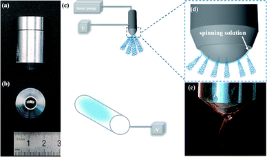 |
| | Fig. 1 (a and b) Pictures of the bead structure needle. (c) Scheme of the spinning device. (d) An enlarged simulation picture of the bead structure and (e) photograph of the nozzle generating a multi-jet. | |
The PAN powder was dissolved in DMF to prepare PAN solutions of 3 wt% and 8 wt%. The solutions were stirred by magnetic force for 3 h at room temperature to make them homogeneous. A 3 wt% aqueous PVP solution was prepared. After connecting the bead nozzle to the propulsion device, the spinning solutions were filled into the bead nozzle structure and loaded into the high voltage power supply between the nozzle and the receiving plate. Moreover, the receiving device was connected to a negative high voltage. In addition, the temperature (27 °C) and the relative humidity in the air (38 ± 2%) were well-maintained during bead spinning. As with traditional needle spinning, bead spinning has many influencing factors, such as voltage, distance, temperature, and humidity. We selected and analyzed the effects of flow, voltage and reception distance on the number of jets through a single factor experiment using a 3 wt% PAN solution. With the voltage set to 20 kV and the receiving distance set at 7 cm, the number of jets was observed by setting the solution flow rate to 0.4 mL min−1, 0.6 mL min−1, 0.8 mL min−1 and 1.0 mL min−1. With a flow rate of 0.6 mL min−1 and the receiving distance set at 7 cm, the number of jets was observed by setting the voltage to 8 kV, 12 kV, 16 kV and 20 kV. With a flow rate of 0.6 mL min−1 and the voltage set at 20 kV, the number of jets was observed by setting the receiving distance to 3 cm, 5 cm, 7 cm and 10 cm. Moreover, we also prepared fibers under suitable conditions with 8% PAN solution and 3% PVP solution. The specific values of the influencing factors of fibers are shown in Fig. S2.†
Characterization and measurements
The exterior patterns of multi-jet formation and the bead structured nozzle were studied using a conventional digital camera (Canon, Japan). The diameter of the sphere at the top of the bead device was measured with a micro-screw meter (0–25, Shanghai). The characteristics and morphology of the fabricated PAN fibrous mat were investigated by scanning electron microscopy (SEM, SHIMADZUX-550) after applying a gold coating. The 2D electric field distribution of the device was simulated with the COMSOL Multiphysics modeling software.
Results and discussion
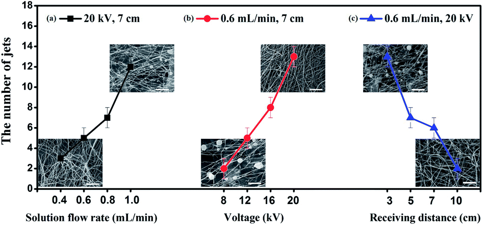
In the case of no high-voltage electric field, the solution flowed out from the gap under the action of thrust and wrapped uniformly around the outer surface of the sphere (Fig. 4(c)). The relevant variables of the number of electrospun jets were investigated by a single factor test. The relevant data is presented in Fig. 2. There is a certain amount of jet error due to photography and human factors. We conducted a number of experiments to obtain the average number of jets and experimental error range (≤±1). The number of jets was observed to be substantially constant based on a large number of tests carried out under the same conditions. In addition, the relationship between the number of jets and different conditions shows an overall specific trend. Under a high-voltage electric field, the solution was stretched and dispersed into a number of jets under the action of the electric field force. With varying voltages and receiving distances, the number of jets increased as the solution flow rate accelerated. As the volume of the solution increased, there was too much solvent in the jet and incomplete volatilization, resulting in the amount of solution deposited being greater than the amount required for spinning. The morphology of the fiber changed from fibrous to beaded (Fig. 2(a)), eventually aggregating into large droplets and falling down. This can be determined for a stable flow rate to ensure that the spinning process proceeds smoothly for a specific concentration of solution in the corresponding electric field. The suitable solution flow rates were obtained by preparing the nanofibers with PVP (3 wt%) and PAN (8 wt%) and comparing them to the appropriate flow rate for PAN (3 wt%). The relatively appropriate flow rates were 0.3 mL min−1, 0.6 mL min−1 and 0.7 mL min−1 for PVP (3 wt%), PAN (3 wt%) and PAN (3 wt%), respectively. The related SEM image is shown in Fig. S2.† We found that liquid flow rates are unequal for different material solutions of the same concentration and solutions of the same material in different concentrations. Furthermore, the appropriate flow rate depends on factors such as the material and its concentration. As we all know, in the traditional electrospinning process, the applied voltage is one of the most important parameters that affect the formation of ultrafine fibers and nanofibers.34 The effect of voltage conditions on the number of jets was also explored. The number of jets increased with an increase in electric field strength. Simultaneously, the fibers become more uniform under a larger electric field force (Fig. 2(b)). Compared to the high voltage required for industrial production, the number of jets for the bead structured electrospinning nozzle could reach 13 at 20 kV. In the case of high productivity, over-consumption of energy was effectively avoided. The distance of the receiving plate also affects the volatilization of the solvent. When the voltage is constant, the greater the distance received, the better the fiber formation. However, as shown in Fig. 2(c), the smaller the electric field force, the lower the number of jets. Appropriate spinning conditions were determined through the exploration of different conditions. It can be observed that the number of jets and the fiber morphology is not directly related with the specific conditions of the experiment.
 |
| | Fig. 2 The relationship between the number of jets and (a) the outflow rate, (b) the voltage and (c) the receiving distance, respectively, and the SEM images of fibers under different conditions (The scale is 10 μm). | |
Fig. 3 is an instant photograph of different numbers of jets ejecting under the corresponding voltage conditions. Simultaneously, the COMSOL Multiphysics model was applied to calculate the electric field distribution around the spinneret at the corresponding voltages.
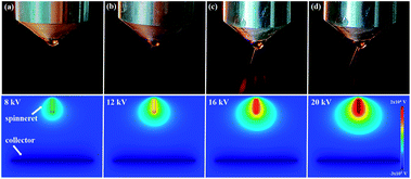 |
| | Fig. 3 The comparison of the multi-jet with different numbers of jets. | |
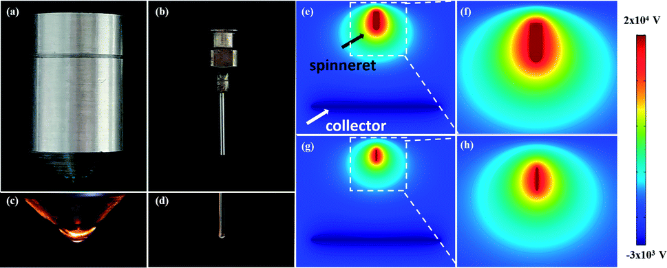
By comparing the physical map to that of the traditional needle, more spinning surface is provided by the bead structure of the nozzle as shown in Fig. 4(c and d). Therefore, it is possible to provide a location for the generation of multiple jets. The electric field strength of the new nozzle shows an increase when providing the same voltage (Fig. 4(e–h)). However, the overall electric field distribution did not change. Hence, the bead structure of the needle will not have much impact on the overall fiber trend.
 |
| | Fig. 4 Physical contrast for (a and b) the same enlargement ratio of the bead nozzle and the laboratory spinning needle and (c and d) the solution flow out of the nozzle without an electric field; simulation of an electric field for bead spinning nozzles (e and f) and traditional needles (g and h). | |
Multi-jet electrospinning of the bead-type structure was carried out in more detail with the voltage set to 20 kV. The jet injection within nine seconds was performed as shown in Fig. 5. By observing the pictures of the jets per second and the video of the spinning process, it is found that the Taylor cone has a dynamic rotating jet in the steady multi-jet process. During electrospinning, there is solution consumption at the point where the Taylor cone begins to occur. When a solution at a particular site was spun into fibers, the solution in its neighborhood would continue to be used and affect the Taylor cone, thus causing it to change position. Because the solution evenly covered the surface, it presents the phenomenon of multiple Taylor cones rotating along the curved surface.
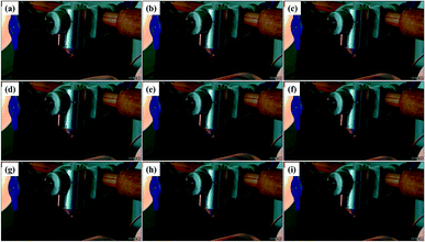 |
| | Fig. 5 The instantaneous images (within 9 seconds) of jet injection with the bead structure nozzle. | |
During the experiment, the solution flow rate was changed. The solution wrapped in a spherical surface with uniform coverage when the flow rate had a certain value. As the flow rate was accelerated, the amount of solution that deposited in a spherical surface increased. In the preparation process, when the solution was deposited as a large liquid, the droplet surface generated a multi-jet phenomenon as shown in Fig. 6(a). In this regard, predecessors27,33 have been studied for surface multi-jet devices. One such study35 shows that the jet formation pattern is primarily manifested in a way that sprays from the Taylor cone surface. There is a strong relationship between jet formation and the polymer concentration and electric field strength. In addition, the shape of the tapered droplets is subject to liquid pressure, surface tension, gravity, surface charge stress, viscosity and so on.36 The formation of the jet at the tip of the nozzle is primarily because of the flow of solution on the surface of the suspended droplet. The charge on the drape droplets is primarily concentrated on the surface, so there is a large surface charge gradient.37 The surface and the overall mechanical analysis of the drape droplets are shown in Fig. 6(a and b). The surface of the drape droplet was primarily subjected to electrostatic force (Pe), viscous stress (Pη), hydrostatic pressure (Ph) and the pressure difference caused by the surface tension (Ps).38 Hence, its tangential stress (Pt) and normal stress (Pn) can be expressed as:
| | |
Pn = Pe,n − Pη,n − Ph − Ps
| (1) |
where
Pe,n is the normal electric field force on the surface of the drape droplet,
Pη,n is the normal viscous stress on the surface of the drape droplet,
Pη,t is the tangential to the surface of the drape droplet and
Pe,t is the tangential direction of the surface of the drape droplet. The volume force (
Fv) of the drape droplet during movement can be expressed as
| | |
Fv = Fg + Fe + Fρ − Fη − Fa − Fc
| (3) |
where
Fg is gravity,
Fe is the electric field force,
Fρ is the inertial force,
Fη is a viscous force,
Fa is air resistance and
Fc is capillary force. The polymer solution undergoes normal movement along the surface of the drape droplets when the sum of the tangential stresses and the sum (
Pt) and the normal stress (
Pn) of the droplet surface are all greater than 0. Simultaneously when the overall downward volume force (
Fv) of the droplets is less than 0, the multi-jet is formed.
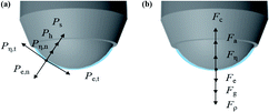 |
| | Fig. 6 The mechanical analysis of surface (a) and of overall (b) drape drops. | |
Two cases were observed in the experiment for the generation of multiple jets (Fig. 7(a and b)). The solution volume was so large that it formed the multi-jet on the droplet surface as shown in Fig. 7(a) and Movie S1.† In the case of solution stacking, the fibers were not uniform and the frequency of beading appeared to be greatly improved. The fiber-forming rate of the product was greatly affected. As shown in Fig. 7(c), a bead appearance was observed in the fiber. Diameter analysis was performed on the non-beaded fibers with an average diameter of about 0.27 μm. The outflow volume of solution was controlled by changing the thrust speed. The solution formed a liquid film on the surface of the beads. The amount of solution consumed by spinning under the action of an electric field force was approximately equal to the amount of liquid flowing out. The multi-jet phenomenon on the sphere surface is demonstrated in Fig. 7(b) and Movie S2.† The SEM image of a multi-jet nanofibers-membrane with no solution accumulation is shown in Fig. 7(d), displaying a typical nonwoven structure composed of smooth and uniform nanofibers prepared with the bead structure nozzle.
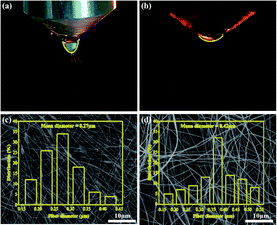 |
| | Fig. 7 Two cases of multiple jets with different solution accumulation: (a) excess solution volume and (b) proper solution volume; scanning electron microscopy micrographs and corresponding diameter analysis of (c) excessive solution buildup and (d) proper solution volume. | |
The average fiber diameter of the nanofibers was about 0.42 μm (Fig. 7(d)). We analyzed the yield of PAN (3 wt%) nanofibers at a flow rate of 0.6 mL min−1, a voltage of 20 kV and a distance of 7 cm. For the analysis of fiber yield, we set the production time to 15 min and obtained the same three nanofiber membranes under the same conditions. The fiber membrane samples were weighed three times and the average value was recorded. Related experimental data are listed in Table 1. The output speed of the solution is 36 mL h−1, which is significantly larger than those employed in the traditional experimental spinning speed (1–5 mL h−1).32 The fiber theoretical yield was calculated to be 1.056 g h−1. Simultaneously, the actual production yield of fiber was calculated and the average production efficiency was 0.918 g h−1. Further, it can be observed that the average productivity of PAN nanofibers is 86%. Compared to the previous fiber production reports (0.01–0.1 g h−1),11 the production of bead-type nozzle spinning has greatly improved.
Table 1 The related yields for PAN (3 wt%) nanofibers
| Sample code |
1 |
2 |
3 |
Average value |
Theoretical value |
| Quality (g) |
0.2235 ± 0.0009 |
0.2370 ± 0.0010 |
0.2280 ± 0.0007 |
0.2295 ± 0.0008 |
0.2640 |
| Yield (g h−1) |
0.894 ± 0.0036 |
0.948 ± 0.0040 |
0.912 ± 0.0028 |
0.918 ± 0.0032 |
1.056 |
Conclusions
A novel and efficient electrospinning bead structure nozzle was developed to increase the yield of nanofibers. It is a good solution to the shortcomings of difficult cleaning and low silk yield from traditional equipment. Our results show that the number of injections can be effectively controlled by adjusting the voltage, the receiving distance and the flow rate of the spinning solution. Only a small amount of material, in this study, was analyzed experimentally and more materials and influencing factors require further study and discovery. The spinning rate is 10–12 times faster than those realized in traditional processes by the bead structure nozzle. The needle can be better utilized in electrospinning by regulating the size of the sphere diameter. Larger sized balls provide a larger surface area that can help increase the number of Taylor cones. In addition, the needle can be further applied in near-field spinning by the finer bead structure nozzle device. The gap between the bead and the outer wall could show different sizes and shapes with further processing of the outer wall, which can expand its scope of application. This method provides a new convenient channel for the mass production of nanofibers.
Conflicts of interest
There are no conflicts to declare.
Acknowledgements
This work was funded by Jilin Province provincial industrial innovation special funds project (2018C041-2), Jilin Provincial Department of Science and Technology Natural Science Foundation (20180101212JC) and Changchun Science and Technology Project (17DY012).
References
- K. Chen, S. Zhang, B. Liu, X. Mao, G. Sun, J. Yu, S. S. Al-Deyab and B. Ding, RSC Adv., 2014, 4, 45760–45767 RSC.
- Z. Cheng, Y. Zhang, Z. Han, L. Cui, L. Kang and F. Zhang, RSC Adv., 2016, 6, 85545–85550 RSC.
- H. Wang, D. Wang, Z. Peng, W. Tang, N. Li and F. Liu, Chem. Commun., 2013, 49, 5568–5570 RSC.
- J. Lin, Y. Cai, X. Wang, B. Ding, J. Yu and M. Wang, Nanoscale, 2011, 3, 1258–1262 RSC.
- D. Li and Y. Xia, Adv. Mater., 2004, 16, 1151–1170 CrossRef CAS.
- L.-H. Zhang, X.-P. Duan, X. Yan, M. Yu, X. Ning, Y. Zhao and Y.-Z. Long, RSC Adv., 2016, 6, 53400–53414 RSC.
- T. Subbiah, G. Bhat, R. Tock, S. Parameswaran and S. Ramkumar, J. Appl. Polym. Sci., 2005, 96, 557–569 CrossRef CAS.
- B. Liu, S. Zhang, X. Wang, J. Yu and B. Ding, J. Colloid Interface Sci., 2015, 457, 203–211 CrossRef CAS PubMed.
- J. T. McCann, D. Li and Y. Xia, J. Mater. Chem., 2005, 15, 735–738 RSC.
- R. Ostermann, D. Li, Y. Yin, J. T. McCann and Y. Xia, Nano Lett., 2006, 6, 1297–1302 CrossRef CAS PubMed.
- J. Varabhas, G. G. Chase and D. Reneker, Polymer, 2008, 49, 4226–4229 CrossRef CAS.
- A. Raza, B. Ding, G. Zainab, M. El-Newehy, S. S. Al-Deyab and J. Yu, J. Mater. Chem. A, 2014, 2, 10137–10145 CAS.
- M. Yu, R. H. Dong, X. Yan, G. F. Yu, M. H. You, X. Ning and Y. Z. Long, Macromol. Mater. Eng., 2017, 302, 1700002 CrossRef.
- S. Theron, A. Yarin, E. Zussman and E. Kroll, Polymer, 2005, 46, 2889–2899 CrossRef CAS.
- W. Tomaszewski and M. Szadkowski, Fibres Text. East. Eur., 2005, 13, 22 Search PubMed.
- B. Ding, E. Kimura, T. Sato, S. Fujita and S. Shiratori, Polymer, 2004, 45, 1895–1902 CrossRef CAS.
- G. Kim, Y.-S. Cho and W. D. Kim, Eur. Polym. J., 2006, 42, 2031–2038 CrossRef CAS.
- A. Varesano, R. A. Carletto and G. Mazzuchetti, J. Mater. Process. Technol., 2009, 209, 5178–5185 CrossRef CAS.
- M. Parhizkar, P. Reardon, J. Knowles, R. Browning, E. Stride, R. Pedley, T. Grego and M. Edirisinghe, Mater. Des., 2017, 126, 73–84 CrossRef CAS.
- S. Xie and Y. Zeng, Ind. Eng. Chem. Res., 2012, 51, 5336–5345 CrossRef CAS.
- Y. Yang, Z. Jia, Q. Li, L. Hou, J. Liu, L. Wang, Z. Guan and M. Zahn, IEEE Trans. Dielectr. Electr. Insul., 2010, 17, 1592–1601 CrossRef.
- S. Padron, A. Fuentes, D. Caruntu and K. Lozano, J. Appl. Phys., 2013, 113, 024318 CrossRef.
- K. Molnár, L. Mészáros and E. Košťáková, eXPRESS Polym. Lett., 2013, 8, 62–72 CrossRef.
- A. Tokarev, D. Asheghali, I. M. Griffiths, O. Trotsenko, A. Gruzd, X. Lin, H. A. Stone and S. Minko, Adv. Mater., 2015, 27, 6526–6532 CrossRef CAS PubMed.
- L. Yang and W. W. F. Leung, Adv. Mater., 2011, 23, 4559–4562 CrossRef CAS PubMed.
- D. Lukas, A. Sarkar and P. Pokorny, J. Appl. Phys., 2008, 103, 084309 CrossRef.
- I. Park, S. S. Kim and W. Kim, Polym. Eng. Sci., 2017 DOI:10.1002/pen.24588.
- Y. Liu and J.-H. He, Int. J. Nonlinear Sci. Numer. Simul., 2007, 8, 393–396 CAS.
- J.-H. He, H.-Y. Kong, R.-R. Yang, H. Dou, N. Faraz, L. Wang and C. Feng, Therm. Sci., 2012, 16, 1263–1279 CrossRef.
- R.-R. Yang, J.-H. He, J.-Y. Yu and L. Xu, Int. J. Nonlinear Sci. Numer. Simul., 2010, 11, 163–164 Search PubMed.
- A. K. Higham, C. Tang, A. M. Landry, M. C. Pridgeon, E. M. Lee, A. L. Andrady and S. A. Khan, AIChE J., 2014, 60, 1355–1364 CrossRef CAS.
- N. Hernández-Navarro, V. González-González, I. E. Moreno-Cortez and M. A. Garza-Navarro, Mater. Lett., 2016, 167, 34–37 CrossRef.
- Y. Liu, L. Zhang, X.-F. Sun, J. Liu, J. Fan and D.-W. Huang, Mater. Lett., 2015, 141, 153–156 CrossRef CAS.
- Y. Liu, L. Dong, J. Fan, R. Wang and J. Y. Yu, J. Appl. Polym. Sci., 2011, 120, 592–598 CrossRef CAS.
- D. H. Reneker and A. L. Yarin, Polymer, 2008, 49, 2387–2425 CrossRef CAS.
- R. Hartman, D. Brunner, D. Camelot, J. Marijnissen and B. Scarlett, J. Aerosol Sci., 2000, 31, 65–95 CrossRef CAS.
- I. Hayati, A. Bailey and T. F. Tadros, Nature, 1986, 319, 41–43 CrossRef.
- B. Ding and J. Y. Yu, Electrospinning and Nanofibers, China Textile and Apparel Press, Beijing, 2011 Search PubMed.
Footnotes |
| † Electronic supplementary information (ESI) available. See DOI: 10.1039/c7ra13125a |
| ‡ Yingying Zhang and Zhiqiang Cheng contribute to the work equally. |
|
| This journal is © The Royal Society of Chemistry 2018 |
Click here to see how this site uses Cookies. View our privacy policy here. 
 Open Access Article
 This Open Access Article is licensed under a Creative Commons Attribution-Non Commercial 3.0 Unported Licence
 *,
Zhaolian Han
*,
Zhaolian Han