DOI:
10.1039/C7RA09822G
(Paper)
RSC Adv., 2018,
8, 102-110
Study on poly(tetrafluoroethylene-co-hexafluoropropylene) hollow fiber membranes with surface modification by a chemical vapor deposition method
Received
4th September 2017
, Accepted 7th December 2017
First published on 20th December 2017
Abstract
In this paper, poly(tetrafluoroethylene-co-hexafluoropropylene) (FEP) hollow fiber membranes, for applications in water purification, were prepared by a melt-spinning method with FEP as the polymer matrix, water-soluble composite powder as the pore-forming agent and dioctyl phthalate (DOP) as the diluent. Then, a layer of polypyrrole (PPy) was deposited on the surface of the FEP hollow fiber membranes by a chemical vapor deposition method. The microstructures and acid/alkali resistance properties of the FEP/PPy composite hollow fiber membranes were investigated. The results showed that the as-prepared FEP hollow fiber membranes had a multi-microporous structure of stretched pores, interfacial pores and dissolved pores. The sponge-like pore structure was distributed homogeneously over the cross-section of the membrane, which brought about a larger pure-water flux. The polymerization of the pyrrole deposit on the surface of the FEP hollow fiber membranes brought about the improvement of hydrophilicity while the reduction of membrane pore size further resulted in the increase of rejection. The acid/alkali resistance results indicated that the un-deposited FEP hollow fiber membranes had excellent acid and alkali resistance, whereas the alkali resistance was weak after PPy deposition.
1. Introduction
In recent years, attention has shifted toward water recovery, reuse, and recycling.1 Emission standards for waste water have become increasingly stringent, requiring an extension of conventional wastewater treatment technologies. Membrane technology has received significant attention and has been widely used in a variety of contexts, including industrial wastewater, municipal sewage and domestic sewage treatment.2,3 As is well known, membrane materials, as the core of membrane technology, play a crucial role in the process of wastewater treatment. To further expand their application in separation applications, the performance requirements of membrane materials are continually increasing.4 Meanwhile, corrosion-resistant membrane materials are frequently used to deal with wastewater of complicated composition.
Perfluorinated polymers have been studied extensively and occupy a niche due to their combination of various properties (superior thermal and chemical stability, corrosion resistance, exceptional abilities to separate fine particles under harsh conditions, etc.).5–7 The most common perfluorinated polymers, which together account for 85% of the production and consumption of perfluorinated polymers, include polytetrafluoroethylene (PTFE), poly(tetrafluoroethylene-co-hexafluoropropylene) (FEP) and perfluoroalkoxy copolymer (PFA).8 However, PTFE fibers or membranes are difficult to manufacture using conventional solution-spinning and melt-spinning methods because of the unusually high melt viscosity and insolubility.9 Compared with PTFE, the meltable property of FEP endows it with good processability for the fabrication of hollow fiber membranes by the melt-spinning method via the introduction of –CF3 bonds into the tetrafluoroethylene, which reduce the crystallinity.10,11 However, there are few studies on the preparation and performance of FEP hollow fiber membranes.12–14
Chemical vapor deposition (CVD) is a technique for the physical modification of membrane surfaces. It can endow the membrane with desirable properties by taking advantage of a gas-phase reaction without changing the composition and weakening the strength of the matrix material. Compared with some traditional membrane surface modification methods, the layer formed by CVD technology is dense and uniform, and firmly bonded with the substrate membrane, the composition is easy to control, and the deposition speed is fast.15,16 Since the electrochemical synthesis of polypyrrole (PPy) in 1979 by Diaz et al., this material has increasingly attracted attention in many applications such as secondary batteries, fuel cells, supercapacitors, sensors, anhydrous rheological fluids and corrosion protection, due to its superior conductivity, biocompatibility, and hydrophilicity.17–21 Gabriel prepared hydrophilic and adherent PPy coatings by a two-step electrochemical method in 2006.22 Jin investigated the effect of PPy coatings on the adhesion and structural properties of ultra-high-molecular-weight polyethylene (UHMWPE) fiber in 2011.23
Recent studies have also reported the preparation of PPy films or PPy-modified layers by the CVD method. Alizadeh prepared a nanostructured conducting PPy film by chemical vapor deposition on interdigital electrodes at room temperature under atmospheric conditions and used it as a gas sensor.24 Xue prepared a PPy-coated fabric strain sensor by the CVD method under low temperature and then studied the mechanisms of its strain-sensing behavior.25 Jun prepared a PPy/UHMWPE fiber by the CVD method and measured the interfacial shear strength of the PPy/UHMWPE fiber under different conditions including oxidant concentration, deposition time and temperature.26 Previous research has mainly focused on the conductive properties and applications of PPy.27–29 However, its chemical stability and hydrophilicity after surface modification have not been extensively studied.
In this study, FEP hollow fiber membranes were prepared by the melt-spinning method with FEP as polymer matrix, water-soluble composite powder as pore-forming agent and dioctyl phthalate (DOP) as the diluent. The prepared FEP hollow fiber membranes showed a multi-microporous structure of stretched pores, interfacial pores and dissolved pores, with the sponge-like structure evenly distributed over the cross-section. Then, a homogeneous PPy layer was polymerized on the outer surface of the FEP hollow fiber membranes by a chemical vapor deposition method instead of the traditional solution polymerization method to prepare FEP/PPy composite hollow fiber membranes. The effect of deposition time on the morphology and performance of the FEP/PPy composite hollow fiber membranes was investigated. In addition, the permeation properties and acid/alkali resistance of the membranes were also tested.
2. Experimental
2.1. Materials
FEP resin (FR460) was purchased from 3F New Material Co., Ltd. (Shanghai, China). The diluent dioctyl phthalate (DOP, analytical reagent grade) was purchased from Tianjin Guangfu Fine Chemical Research Institute. The pore-forming agent, a composite powder (a mixture of nanoscale SiO2 particles, interface treating agent and KCl), was provided by Tianjin Motimo Membrane Technology Co., Ltd. (Tianjin, China). Sodium hydroxide (NaOH, analytical reagent grade), sulfuric acid (H2SO4, 98%) and ferric chloride (FeCl3, analytical reagent grade) were purchased from Tianjin Kermel Chemical Reagent Co., Ltd. (Tianjin, China). PVDF hollow fiber membranes (prepared by the melt-spinning method) were provided by Tianjin Motimo Membrane Technology Co., Ltd. (Tianjin, China). Pyrrole (Py) was purchased from Shanghai Kefeng Industry & Commerce Co., Ltd. (Shanghai, China). All the reagents were used as received without further purification.
2.2. Preparation of FEP hollow fiber membranes
The FEP resin and composite powder were dried in a vacuum oven (1 bar, 90 ± 1 °C) for 12 h to remove moisture. Then, the FEP resin, composite powder and DOP were homogeneously mixed in a certain weight ratio under vigorous mechanical stirring by a high-speed mixer. After that, the mixture was melted in a screw extruder, followed by transportation in the molten state to be spun into hollow fibers via the melt-spinning method by a twin-screw. Subsequently, the FEP hollow fiber membranes were obtained after immersion in alcohol and pure water. The process of melt spinning is shown in Fig. 1, while the parameters and compositions are tabulated in Table 1.
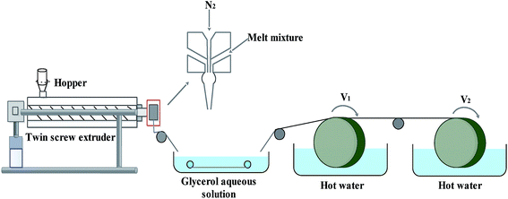 |
| | Fig. 1 Schematic diagram of the melt-spinning process. | |
Table 1 Fabrication parameters and compositions of FEP hollow fiber membranes
| Dope composition |
FEP/composite powder/DOP = 3![[thin space (1/6-em)]](https://www.rsc.org/images/entities/char_2009.gif) :2:1 :2:1 |
| Bore fluid |
N2 |
| External coagulation bath |
Glycerol aqueous solution |
Water |
Water |
| Coagulation bath temperature (°C) |
120 |
90 |
90 |
| Air gap (cm) |
3 |
| Take-up speed |
Free flow |
| Spinneret dimension (mm) |
OD/ID = 2.6:2.0 |
2.3. Preparation of FEP/PPy composite hollow fiber membranes
A 30 wt% ethanol solution of FeCl3 was prepared by dissolving FeCl3 powder in ethanol under constant agitation. Then the FEP hollow fiber membranes were soaked in the 30 wt% alcohol solution of FeCl3 (catalyst) for 30 min. After that, as shown in Fig. 2, the membranes were placed into a self-made CVD reactor containing a reaction tank filled with liquid-phase Py monomer under a dry vacuum environment to form the thin PPy coatings. The vapour phase polymerization of PPy proceeded on the surface of the membranes under vacuum for 10 min, 20 min and 30 min, respectively. Finally, these FEP/PPy composite hollow fiber membranes were thoroughly washed with deionized water by ultrasonic treatment in order to remove any excess monomer or loose PPy that remained, and then dried in an oven at 50 °C for 24 h under vacuum. The deposition parameters of the FEP/PPy composite hollow fiber membranes are tabulated in Table 2.
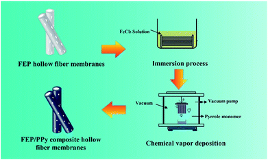 |
| | Fig. 2 Diagram of CVD process and apparatus. | |
Table 2 Deposition parameters of FEP/PPy composite hollow fiber membranes
| Code |
FeCl3 mass fraction (wt%) |
Deposition time (min) |
| M0 |
— |
— |
| M10 |
30 |
10 |
| M20 |
30 |
20 |
| M30 |
30 |
30 |
2.4. Characterization
The morphology of the membranes was evaluated by scanning electron microscopy (SEM; FESEM S4800 and SEM TM3030, Hitachi, Japan), and the roughness of the membranes was measured by confocal laser scanning microscopy (CLSM, Zeiss CSM700, Zeiss, Germany). Water contact angle (WCA) measurements were performed using an optical contact angle meter (model DSA100, KRUSS, Germany) by the sessile drop method using water drops. Fourier-transform infrared spectroscopy (FTIR, Nicolet iS50, Thermo Fisher Scientific, USA) was used to identify the surface functional groups of the FEP and FEP/PPy membranes. The thermogravimetric analysis (TGA) of the membrane samples was performed using a TGA instrument (TA-SDT Q600, TA Instruments, USA) under nitrogen atmosphere at a heating rate of 10 °C min−1 from room temperature to 800 °C (membrane sample weights ranged from 6 to 10 mg). The mean pore size and porosity of the samples were tested by an automatic mercury porosimeter (Auto pore IV9500, Micromeritics, USA). The tensile strength of the membranes was determined by using an electronic tensile tester (JBDL-200N, China) at room temperature at a tensile rate of 10 mm min−1.
2.5. Membrane permeability
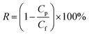
The pure water flux (PWF) and rejection of the prepared membranes were determined using a self-made filtration experimental setup, as shown in Fig. 3, under a pressure of 0.15 MPa at a temperature of 25 °C. All the membrane samples were pre-compacted under a pressure of 0.2 MPa for 30 min in order to ensure steady filtration. After that, carbon ink solutions (1 g L−1, average particle size: 192 nm) were used to test the separation performance of the membranes. The PWF and carbon ink rejection were calculated by eqn (1) and (2), respectively:| |
 | (1) |
where J is the PWF (L m−2 h−1), V is the total volume of the solution in the permeate side (L), T is the operation time (h), and A is the effective membrane area (m2).| |
 | (2) |
where R is the rejection to carbon ink (%), and Cf and Cp are the carbon ink concentration of the feed solution and permeate water, respectively (g L−1).
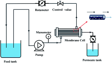 |
| | Fig. 3 Schematic diagram of filtration system. | |
2.6. Acid/alkali resistance
The FEP hollow fiber membranes and FEP/PPy composite hollow fiber membranes were each separately immersed in H2SO4 (mass concentration, 30%) and NaOH (mass concentration, 30%) aqueous solutions for 60 days at room temperature to evaluate the tolerance to acid and alkaline conditions. After 60 days, the treated membranes were washed with distilled water for testing.
3. Results and discussion
3.1. Membrane morphologies
The SEM images in Fig. 4 show the cross-section and surface morphology of the FEP hollow fiber membranes. It can be clearly seen from Fig. 4a that the FEP hollow fiber membranes were homogeneous membranes. Moreover, sponge-like structures could be clearly observed when the magnification was increased, as shown in Fig. 4b. The outer and inner surface images exhibited a relatively high porosity and both stretched pores and dissolved pores can be observed from the surface images in Fig. 4c and d. The results showed that the prepared FEP hollow fiber membranes had a multi-microporous structure of stretched pores, interfacial pores and dissolved pores, with the sponge-like structure evenly distributed over the cross-section. A plausible mechanism for the formation of this structure is that the diluent DOP was extracted to yield a microvoid structure and the composite powder acted as a physical barrier to eliminate contact between the polymers and pores created after the KCl was dissolved. Meanwhile, the solubility parameter of DOP is relatively close to that of the extruded species, FEP, compared to other solvents sometimes used in the process of melt spinning.11 Therefore, the introduction of DOP not only improved the processability of the polymer mixture but also promoted membrane porosity. The 3D images of the FEP hollow fiber membranes are shown in Fig. 4d and the roughness parameters of the surfaces (shown in Table 3) showed that the average surface roughness was about 3.104 μm. This rough surface may contribute to the surface modification considerably.
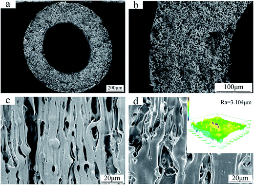 |
| | Fig. 4 Morphologies of the FEP hollow fiber membranes (M0); (a): whole cross-section; (b): enlarged cross-section; (c): inner surface; (d): outer surface and CLSM 3D images. | |
Table 3 Properties of FEP/PPy composite hollow fiber membranes
| Samples |
Mean pore size (nm) |
Porosity (%) |
Roughness average (μm) |
WCA (°) |
Mechanical strength (MPa) |
| M0 |
561.4 ± 40.3 |
62.0 ± 4.5 |
3.104 ± 0.441 |
122.6 ± 3.48 |
5.01 ± 0.19 |
| M10 |
250.4 ± 18.2 |
36.9 ± 2.7 |
2.714 ± 0.328 |
113.3 ± 2.75 |
4.97 ± 0.12 |
| M20 |
113.7 ± 20.1 |
32.9 ± 2.9 |
1.706 ± 0.156 |
70.2 ± 3.36 |
5.03 ± 0.07 |
| M30 |
100.3 ± 8.9 |
31.5 ± 1.0 |
2.524 ± 0.417 |
45.2 ± 2.53 |
5.00 ± 0.21 |
As shown in Fig. 5, after Py polymerization on the surface of the FEP hollow fiber membranes, these FEP/PPy composite hollow fiber membranes turned black, indicating that PPy was well dispersed and polymerized on the surface. The effects of deposition time on the morphologies of the FEP/PPy composite hollow fiber membranes are shown in Fig. 6. It was observed that some particles were attached to the FEP/PPy composite hollow fiber membrane surfaces. As the deposition time increased, a comparatively smooth surface was formed, showing that more PPy was deposited and polymerized to fill the holes and cracks on the outer surface. However, a long deposition time also tends to make the surface become rough, which was consistent with the surface roughness of the composite hollow fiber membranes as depicted in Fig. 6(a1–a3). With increased PPy loading, the apparent membrane surface became rougher, as shown in Table 3. The cross-section images of the FEP/PPy composite hollow fiber membranes displayed a very thin layer.
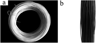 |
| | Fig. 5 Digital photos of (a): FEP hollow fiber membranes and (b): FEP/PPy composite hollow fiber membranes. | |
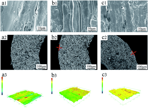 |
| | Fig. 6 Morphologies of FEP/PPy composite hollow fiber membranes: (a): M10; (b): M20; (c): M30; (1): outer surface; (2): cross-section; (3): CLSM 3D images. | |
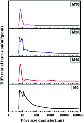
3.2. Pore size and distribution
Fig. 7 shows the pore size and its distribution for the FEP hollow fiber membranes and FEP/PPy composite hollow fiber membranes. M0 had a wide pore size distribution because of the multipore structure, leading to a larger porosity. For M10–M30, the formation of PPy led to the pores becoming smaller, which resulted in a significant reduction in pore size and porosity.
 |
| | Fig. 7 Pore size and pore size distribution. | |
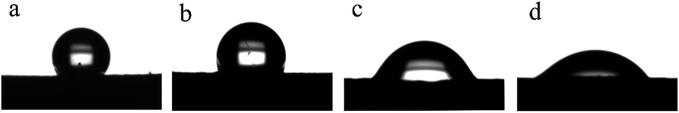
3.3. Hydrophilicity
Fig. 8 shows the static water contact angle of the membranes produced at different deposition times. As is well known, the pore size, surface roughness and composition of a membrane are the main factors impacting its WCA value. The M0 membrane exhibited strong hydrophobicity not only because of the hydrophobicity of the FEP material itself but also because of the high surface roughness. As expected, the contact angles of the M10, M20 and M30 membranes became lower than that of the M0 membrane after greater amounts of the hydrophilic PPy were polymerized on the surface. It has been shown that when the roughness of membranes is increased, hydrophilic membranes become more hydrophilic, and hydrophobic membranes become more hydrophobic.30–33 When the deposition time increased from 10 min to 30 min, the water contact angles of the membranes were considerably reduced from 113.3 ± 2.75° for M10 to 45.2 ± 2.53° for M30. The increased roughness of the membranes may be responsible for this.
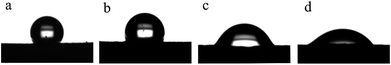 |
| | Fig. 8 WCA images of the membranes: (a): M0; (b): M10; (c): M20; (d): M30. | |
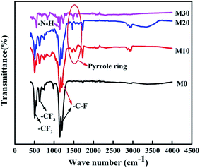
3.4. FTIR analysis
The FTIR spectra of the FEP hollow fiber membranes and FEP/PPy composite hollow fiber membranes are shown in Fig. 9. For the original membrane M0, as indicated by the arrows in the figure, the characteristic two bands at 1250 and 1149 cm−1 were ascribed to –C–F stretching vibrations, and the 638 cm−1 band was ascribed to the –CF2 rocking or wagging–bending vibrations of FEP. Compared with M0, –N–H stretching vibrations (at 1294 cm−1) appeared in M10–M30, and the new bands at 1570 and 1490 cm−1 could be assigned to the characteristic peaks of pyrrole rings at the surface, confirming the polymerization of PPy on the membrane surfaces of M10–M30.
 |
| | Fig. 9 FTIR spectra of the FEP hollow fiber membranes and FEP/PPy composite hollow fiber membranes. | |
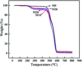
3.5. Thermal stability
The prepared membranes were evaluated by TGA to better understand their thermal stability and decomposition temperature. Fig. 10 displays the TGA curves of the samples. It clearly illustrates that the original membrane M0 showed initial signs of degradation at about 470 °C, while the composite hollow fiber membranes M10–M30 showed two quality-fading processes. Specifically, they began to decompose at about 220 °C, with a weight loss corresponding to the thermal dehydration of PPy, and as the temperature rose the second attenuation appeared at about 475 °C, with a weight loss corresponding to the thermal dehydration of FEP, which was similar to M0. The prepared membranes retained excellent chemical resistance and thermal stability.
 |
| | Fig. 10 TGA curves of the FEP hollow fiber membranes and FEP/PPy composite hollow fiber membranes. | |
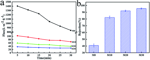
3.6. Permeation performance
The results of PWF and carbon ink rejection of the membranes are shown in Fig. 11. The PWF of M0 was up to 842 L m−2 h−1 after testing for 30 min, while the PWF of the M10, M20 and M30 membranes were all lower at under 100 L m−2 h−1, but the flux decline rates were also smaller than for M0, as shown in Fig. 11a. The lower porosity and smaller average pore size due to the PPy layer might be responsible for this behavior. It can be concluded that the increased hydrophilicity gave the FEP/PPy composite hollow fiber membranes better permeability and lower flux decline rates compared with the FEP hollow fiber membranes. Moreover, the carbon ink rejection performances of the membranes after 30 min of running are also given in Fig. 11b, in which the carbon-black in the carbon ink solution served as the filter medium. For M0, the existence of large pores in the structure resulted in low carbon ink rejection. The accumulation of PPy particles on the membrane surface and inside the membrane pores, forming a cake layer, therefore played an important role to block the transport of carbon-black particles through the membranes. We found that the deposition and polymerization of PPy on the membrane surface produced FEP hollow fiber membranes with markedly improved rejection over the pure FEP hollow fiber membranes. This further demonstrates the benefits of CVD as an effective membrane modification method.
 |
| | Fig. 11 PWF (a) and carbon ink rejection (b) of the FEP hollow fiber membranes and FEP/PPy composite hollow fiber membranes. | |
3.7. Acid/alkali resistance
Fig. 12 and 13 show the digital photos, SEM images and FTIR spectra of the FEP hollow fiber membranes and FEP/PPy composite hollow fiber membranes before and after acid and alkali treatment. As shown in Fig. 12(a1–c1), for M0, there were no obvious changes of membrane surface morphology after acid and alkali treatment for 60 days, while the surface color became slightly darker after alkali treatment. It was found from the FTIR spectra that the functional groups of the M0 membrane did not change, which indicated that the membrane had good acid and alkali stability. After the same treatment, the surface morphology of the FEP/PPy composite hollow fiber membranes showed no obvious change after acid treatment (shown in Fig. 13(c2)). However, the external appearance and surface morphology of the FEP/PPy composite hollow fiber membranes (shown in Fig. 13(a2) and (b2)) clearly indicated that the PPy was detached from the membrane surface after alkali treatment, and the surface showed a stretched pore structure. The FTIR spectra also showed the characteristic peaks of FEP. We drew the conclusion that the FEP/PPy composite hollow fiber membranes exhibited a good acid resistance, but their alkali resistance was weakened. A possible reason is that prolonged alkali treatment led to ring oxidation, giving rise to the formation of C–O and C![[double bond, length as m-dash]](https://www.rsc.org/images/entities/char_e001.gif) O, which destroyed the PPy structure.34,35
O, which destroyed the PPy structure.34,35
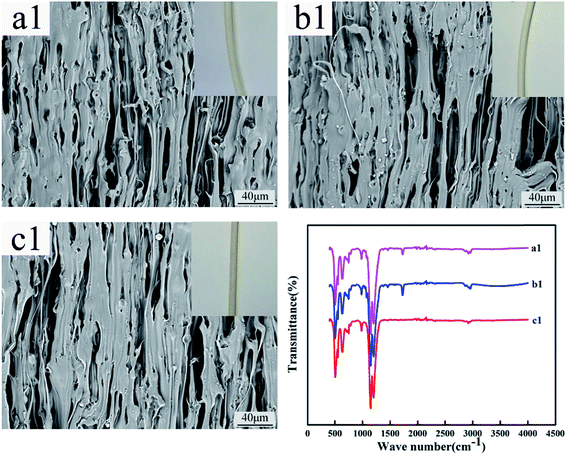 |
| | Fig. 12 Morphology and FTIR of M0 before and after acid and alkali treatment (a1–c1: untreated membrane, acid-treated membrane and alkali-treated membrane). | |
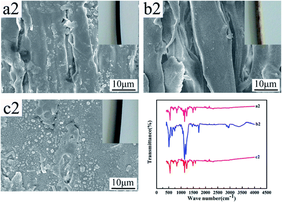 |
| | Fig. 13 Morphology and FTIR of M30 before and after acid and alkali treatment (a2–c2: untreated membrane, alkali-treated membrane and acid-treated membrane). | |
4. Conclusion
FEP hollow fiber membranes and FEP/PPy composite hollow fiber membranes were successfully prepared by the melt-spinning method and chemical vapor deposition method. The FEP hollow fiber membranes had a multi-microporous structure of stretched pores, interfacial pores and dissolved pores, with the sponge-like pore structure distributed homogeneously over the cross-section of the membrane. This structure endowed the membrane with a large membrane pore size and porosity, giving the as-prepared membrane a high pure water flux (842 L m−2 h−1) and a low rejection. The polymerization of pyrrole deposits on the surface of the FEP hollow fiber membranes brought about the improvement of hydrophilicity while reducing the membrane pore size, which further resulted in the increase in rejection. The results of acid/alkali resistance experiments indicated that the un-deposited FEP hollow fiber membranes had excellent acid and alkali resistance, whereas the alkali resistance was weakened after PPy deposition. The results of this study suggest that CVD might be an effective membrane modification method.
Conflicts of interest
There are no conflicts to declare.
Acknowledgements
This work was supported by the National Natural Science Foundation of China (No. 51673149).
References
- T. Melin, B. Jefferson, D. Bixio, C. Thoeye, W. De Wilde, J. De Koning, J. van der Graaf and T. Wintgens, Desalination, 2006, 187, 271–282 CrossRef CAS.
- C. Visvanathan, R. B. Aim and K. Parameshwaran, Crit. Rev. Environ. Sci. Technol., 2000, 30, 1–48 CrossRef CAS.
- T. Wintgens, T. Melin, A. Schäfer, S. Khan, M. Muston, D. Bixio and C. Thoeye, Desalination, 2005, 178, 1–11 CrossRef CAS.
- K. P. Lee, T. C. Arnot and D. Mattia, J. Membr. Sci., 2011, 370, 1–22 CrossRef CAS.
- W. T. Tsai, H. P. Chen and W. Y. Hsien, J. Loss Prev. Process Ind., 2002, 15, 65–75 CrossRef.
- M. Yamabe, K. Akiyama, Y. Akatsuka and M. Kato, Eur. Polym. J., 2000, 36, 1035–1041 CrossRef CAS.
- T. Matsumoto, A. Ohashi, N. Ito, H. Fujiwara and T. Matsumoto, Biosens. Bioelectron., 2001, 16, 271–276 CrossRef CAS PubMed.
- Z. Jiang, Z. Guo, Z. Jia, C. Xiao and S. An, e-Polym., 2016, 16, 171–176 CAS.
- C. F. Bosse and R. R. Kowligi, Uniformly expanded PTFE film, US Pat., 5321109, 1994.
- Q.-l. Huang, C.-f. Xiao, X.-y. Hu and X.-f. Li, Desalination, 2011, 277, 187–192 CrossRef CAS.
- Q.-L. Huang, C. Xiao, Z.-Q. Miao, X. Feng and X.-Y. Hu, Desalin. Water Treat., 2013, 51, 3948–3953 CrossRef CAS.
- Q. Huang, C. Xiao, X. Hu and S. An, J. Mater. Chem., 2011, 21, 16510 RSC.
- K. Chen, C. Xiao, Q. Huang, H. Liu, H. Liu, Y. Wu and Z. Liu, Desalination, 2015, 375, 24–32 CrossRef CAS.
- Z. Cui, E. Drioli and Y. M. Lee, Prog. Polym. Sci., 2014, 39, 164–198 CrossRef CAS.
- M. Ma, Y. Mao, M. Gupta, K. K. Gleason and G. C. Rutledge, Macromolecules, 2005, 38, 9742–9748 CrossRef CAS.
- K. L. Choy, Prog. Mater. Sci., 2003, 48, 57–170 CrossRef CAS.
- K. H. An, K. K. Jeon, J. K. Heo, S. C. Lim, D. J. Bae and Y. H. Lee, J. Electrochem. Soc., 2002, 149, A1058 CrossRef CAS.
- P. Mishra and R. Jain, Int. J. Hydrogen Energy, 2016, 41, 22394–22405 CrossRef CAS.
- Q. Zhou, C. M. Li, J. Li, X. Cui and D. Gervasio, J. Phys. Chem. C, 2015, 111, 11216–11222 Search PubMed.
- C. Serge, R. E. Ionescu, H. Sebastien, B. Laurent, D. Martine and R. S. Marks, Anal. Chem., 2006, 78, 7054–7057 CrossRef PubMed.
- M. A. Smit, A. L. Ocampo, M. A. Espinosa-Medina and P. J. Sebastián, J. Power Sources, 2003, 124, 59–64 CrossRef CAS.
- S. Gabriel, M. Cécius, K. Fleuryfrenette, D. Cossement, M. Hecq, N. Ruth, A. R. Jérôme and C. Jérôme, Chem. Mater., 2007, 19, 2364–2371 CrossRef CAS.
- X. Jin, W. Wang, L. Bian, C. Xiao, G. Zheng and C. Zhou, Synth. Met., 2011, 161, 984–989 CrossRef CAS.
- N. Alizadeh, A. A. Ataei and S. Pirsa, J. Iran. Chem. Soc., 2015, 12, 1585–1594 CrossRef CAS.
- P. Xue, X. M. Tao and H. Y. Tsang, Appl. Surf. Sci., 2007, 253, 3387–3392 CrossRef CAS.
- J. Song, China Synth. Fiber Ind., 2007, 30, 14–17 CAS.
- C. M. Li, C. Q. Sun, W. Chen and L. Pan, Surf. Coat. Technol., 2005, 198, 474–477 CrossRef CAS.
- S. Popescu, C. Ungureanu, A. M. Albu and C. Pirvu, Prog. Org. Coat., 2014, 77, 1890–1900 CrossRef CAS.
- M. A. Chougule, S. G. Pawar, P. R. Godse, R. N. Mulik, S. Sen and V. B. Patil, Soft Nanosci. Lett., 2011, 01, 6–10 CrossRef CAS.
- M. S. Bell, A. Shahraz, K. A. Fichthorn and A. Borhan, Langmuir, 2015, 31, 6752–6762 CrossRef CAS PubMed.
- J. R. Mccutcheon and M. Elimelech, J. Membr. Sci., 2008, 318, 458–466 CrossRef CAS.
- P. Bijma, J. A. Van Arendonk and J. A. Woolliams, Appl. Surf. Sci., 2011, 257, 5213–5218 CrossRef.
- M. Karlsson, P. Forsberg and F. Nikolajeff, Langmuir, 2010, 26, 889–893 CrossRef CAS PubMed.
- K. G. Neoh, T. T. Young, E. T. Kang and K. L. Tan, J. Appl. Polym. Sci., 2015, 64, 519–526 CrossRef.
- K. Cheah, M. Forsyth and V. T. Truong, Synth. Met., 1998, 94, 215–219 CrossRef CAS.
|
| This journal is © The Royal Society of Chemistry 2018 |

 Open Access Article
 This Open Access Article is licensed under a Creative Commons Attribution-Non Commercial 3.0 Unported Licence
 *,
Qing-lin Huang,
Yan Huang,
Chun Wang and
Hai-liang Liu
*,
Qing-lin Huang,
Yan Huang,
Chun Wang and
Hai-liang Liu