DOI:
10.1039/C7QM00563F
(Research Article)
Mater. Chem. Front., 2018,
2, 530-536
Synthesis and properties of a twin donor molecule composed of cofacially stacked dihydrodiazapentacenes†
Received
7th December 2017
, Accepted 10th January 2018
First published on 12th January 2018
Abstract
A clip-shaped donor–acceptor–donor (D–A–D) molecule (1) has been prepared with 6,13-dihydro-6,13-diazapentacene (DHDAP) as a building unit. X-Ray single crystal analysis revealed the structure of 1 whose DHDAP moieties confront each other in close proximity. The electrochemical measurements showed that this molecule could be oxidized up to the tetracation reflecting its twin donor structure with two DHDAP units. Spectroscopic measurements (UV/vis-NIR, ESR) of 1˙+ suggested the full delocalization of the radical spin over the two DHDAP units. The stable radical cation salt 1˙+·[SbF6]− was obtained by chemical oxidation of 1. The packing structure of 1˙+·[SbF6]− was a kind of segregated stacking, which is desirable for charge conduction. Actually, photoconductivity measurement by the microwave technique revealed that 1˙+·[SbF6]− has more than 10 times higher photoconductivity than its neutral state with an extraordinary long lifetime of charge separated states, suggesting its feasibility as light-energy harvesting cores even in the near-IR region.
Introduction
π-conjugated molecules with a rigid and planar structure have been utilized as key building blocks of functional organic materials. For example, various kinds of planar π-conjugated molecules such as anthracenes,1 porphyrins,2,3 hexabenzocoronenes4etc. have been widely used to provide molecular materials with desired functions such as photophysical and electrical conductive properties. In this context, azaacenes, which are the nitrogen-substituted analogues of acenes, are also an intriguing class of compounds due to their facile syntheses and higher stability compared with the larger acenes such as pentacene.5,6 Among the family of azaacenes, 6,13-diazapentacene (DAP) is a useful building block of organic electronic materials as a nitrogen-substituted analogue of pentacene (Fig. 1). One of the important features of DAP is that DAP can be interconverted with 6,13-dihydro-6,13-diazapentacene (DHDAP) by a redox reaction. DHDAP is a good electron donor derived from its amino nitrogen moieties, while DAP is an inherently electron deficient species as compared with pentacene. In 2015, we reported a synthesis of double heterohelicenes from DHDAP derivatives as an example of construction of novel π-systems using azaacenes.7 The key reaction of the work was a highly site-selective C–N bond formation by oxidative coupling between DHDAP units. Herein, we demonstrate another example of a three-dimensional π-system bricolage using a DHDAP skeleton. We selected a nucleophilic substitution reaction of monoalkylated DHDAP (2) having a NH group as a key reaction in this work, aiming to synthesize a clip-shaped azaacene-dimer consisting of two DHDAP moieties fixed in a face-to-face manner tethered by an ortho-phenylene unit (1). This compound is regarded as a twin donor molecule.8,9 Twin donor molecules are an interesting class of materials because one-electron oxidation of these compounds can give quasi-“D2X” type salts (D: donor, X: anion), which often show a variety of electronic properties, such as superconductivity, metal–insulator transition, as well as other phenomena relevant to strongly correlated electron systems.10 In this paper, the synthesis, structures, and electronic properties are discussed for the twin donor molecule 1 and its cationic states.
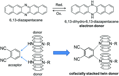 |
| | Fig. 1 Molecular design of this work. | |
Results and discussion
Synthesis
A monoalkylated DHDAP 2 was synthesized according to our previous report.7 Then 2 was introduced by double nucleophilic addition into 4,5-difluorophthalonitrile after proton abstraction by sodium hydride. After work up and purification by silica gel chromatography, the target product 1 was successfully prepared in 49% yield (Scheme 1). A dimer of 2 connected by one covalent bond was also generated as a by-product in 9% yield, and this by-product was determined to be a cruciform dimer of 2, which was firstly synthesized by oxidative dimerization of 2 in our previous work.7 Interestingly, when 1,2-difluorobenzene was used in place of 4,5-difluorophthalonitrile as an electrophile, this cruciform dimer was obtained in 80% yield without the products of the nucleophilic addition.
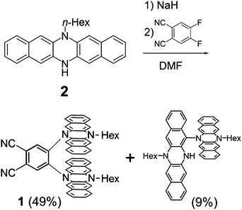 |
| | Scheme 1 Synthesis of 1. | |
Crystal structure of 1
The structure of 1 was successfully clarified by X-ray crystal structure analyses. There exist two crystallographically independent structures of 1 (1-A and 1-B) in the crystal (Fig. 2a). Focussing on each molecular structure, the two DHDAP units in 1-A were cofacially and closely stacked, and the distances between inner–inner and outer–outer nitrogen atoms were 2.86 and 4.21 Å (Fig. 2b). The structure of 1-B was almost similar to that of 1-A, although the two DHDAP units were slightly bent in a butterfly fashion (Fig. 2c). In a unit cell, there are four pairs of 1-A and 1-B confronted with each other in a head-to-tail manner. The pairs aligned in a columnar fashion with a twist angle of ca. 65°, and then π–π contacts between DHDAP units of 1 belonging to different pairs were thought to be small.
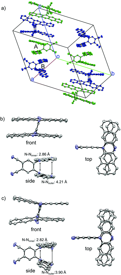 |
| | Fig. 2 X-ray crystal structures of 1. (a) Packing structure, (b) structure of 1-A, and (c) structure of 1-B. The hydrogen atoms, n-hexyl groups and solvent molecules are omitted for clarity. Thermal ellipsoids are set at 50% probability. | |
DFT calculations of 1
We carried out DFT calculations for the model compound of 1 in which two n-hexyl groups are replaced by methyl groups (1′). The calculation with the B3LYP functional could not reproduce the crystal structure of 1 but gave a butterfly-shaped structure of which two DHDAP units were largely bent to the opposite side (Fig. S4a, ESI†). This is due to the poor applicability of the B3LYP functional for describing the intramolecular π–π interaction as frequently pointed out.11 On the other hand, the calculation in the M06-2X functional, which has improved accuracy for describing non-bonding interactions, well reproduced the crystal structure of 1 (Fig. S4b, ESI†). As shown in Fig. 3, the HOMO and the (HO−1)MO of 1′ are distributed on the two DHDAP moieties and the dicyanobenzene unit has almost no MO coefficients, whereas the LUMO is localized on the dicyanobenzene unit, reflecting the structure of 1 having the segmented donor and acceptor moieties. The (HO−1)MO and the HOMO are constructed by the overlapping of the original HOMOs of two DHDAP units in a bonding and anti-bonding fashion, respectively, and due to this orbital interaction, the orbital energies of the HOMO and the (HO−1)MO were calculated to be split by 0.28 eV on this level of theory.
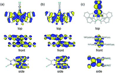 |
| | Fig. 3 (a) (HO−1)MO, (b) HOMO and (c) LUMO of 1′ calculated at the M06-2X/6-31G(d) level. | |
Photophysical properties
The UV/vis absorption spectra of 1 and dihexyl-substituted DHDAP (3) as a reference compound in dichloromethane are shown in Fig. 4. The spectral shape of 1 was basically similar to that of 3 but slightly blue-shifted. This blue-shift could be explained by the H-type stacking of two DHDAP units.12 However, looking closely at the visible region, 1 has a weak absorption band with a peak top at around 540 nm. Due to this absorption band, 1 has a red-brown colour in solid and solution states, in contrast to the pale-yellow colour of 2 and 3. This UV/vis absorption spectrum of 1 was qualitatively reproduced by the TD-DFT calculation at the M06-2X/6-31G(d) level and the lowest energy band was assigned to the transition from the HOMO and the (HO−1)MO on the DHDAP moieties to the LUMO on the dicyanobenzene moiety (Fig. S5, ESI†). However, the calculation with the M06-2X functional largely overestimated the transition energies. On the other hand, the TD-DFT calculation with the B3LYP functional at the optimized geometry with the M06-2X functional gave improved results (Fig. S6 and Table S4, ESI†). The fluorescence measurements clearly reflected the cofacially stacked twin donor structure of 1. Whereas 3 shows bright blue emission (3: λem = 435 nm, Φf = 0.48), 1 showed no emission. This is in stark contrast to the fluorescent nature of the analogue of 1 which has two carbazole units instead of DHDAP units (Φf = 0.47),13 suggesting the fluorescence quenching by the strong through-space interaction between two DHDAP units in 1.
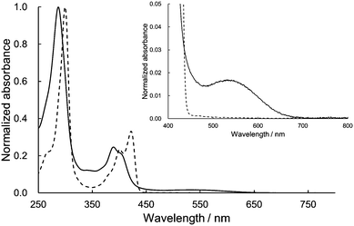 |
| | Fig. 4 Absorption spectra of 1 (solid) and 3 (dashed) in CH2Cl2. The insets show the magnified view of the visible region. | |
Electrochemistry
The redox properties of 1 were investigated by measuring cyclic voltammetry (CV) and differential pulse voltammetry (DPV). The results of CV showed three reversible redox couples, and judging from the digital simulation of DPV,14 the first and second correspond to one-electron oxidation and the third to a simultaneous two-electron oxidation process, respectively (Fig. 5a). By comparing with the CV of 3 (Fig. S3, ESI†), the first and the second oxidation of 1 could be attributed to the consecutive one-electron removals from two DHDAP units. The first oxidation potential of 1 was shifted positively by 90 mV compared with 3, suggesting the effect of the direct substitution of the electron-accepting dicyanobenzene to the DHDAP units. The splitting between the first and second oxidation potentials (ΔE = E2ox − E1ox) of 1 was 184 mV. This value is smaller than those of N,N,N′,N′-tetraanisyl-o-phenylenediamine (405 mV)15 and 1,2-bis(N-phenothiazinyl)-4,5-dimethyl-benzene (340 mV).16 It should be noted that the smaller ΔE value of 1 does not necessarily mean the weaker electronic coupling between the two donor units in 1 compared with these two twin donor analogues because the donor units are in close proximity to each other in these molecules.17 The decreased ΔE value of 1 could be largely attributed to the decreased electrostatic repulsion between the two DHDAP units in 1˙+ due to the extension of the donor units. No reduction waves leading to the anionic species of 1 were observed under the measurement conditions (Table 1).
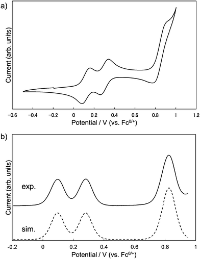 |
| | Fig. 5 (a) Cyclic voltammograms and (b) differential pulse voltammograms of 1, measured in CH2Cl2 containing 0.1 M n-Bu4NBF4 at 298 K (scan rate 100 m V s−1). | |
Table 1 Oxidation potentials (V versus Fc0/+) of 1 and 3 determined by the digital simulations of DPV in CH2Cl2 (0.1 M n-Bu4NBF4)
|
|
E
1
|
E
2
|
E
3
|
E
4
|
|
1
|
0.096 |
0.280 |
0.815 |
0.835 |
|
3
|
0.006 |
0.622 |
— |
— |
Charge delocalization in cationic states of 1
Due to the twin donor structure linked via an ortho-phenylene unit, the radical cation of 1 is an intriguing system as a purely organic mixed-valence (MV) system.18 To investigate the electronic properties of 1˙+, the UV/vis-NIR absorption spectra of 1˙+ generated by chemical oxidation with AgSbF6 were measured in acetonitrile. As shown in Fig. 6, 1˙+ showed an intense band at 17![[thin space (1/6-em)]](https://www.rsc.org/images/entities/char_2009.gif) 500 cm−1 (570 nm) and a broad band around 13
500 cm−1 (570 nm) and a broad band around 13![[thin space (1/6-em)]](https://www.rsc.org/images/entities/char_2009.gif) 200 cm−1 (760 nm) corresponding to the absorption of the radical cation of the DHDAP unit. Furthermore, 1˙+ also showed broad absorption in the NIR region extending from 10
200 cm−1 (760 nm) corresponding to the absorption of the radical cation of the DHDAP unit. Furthermore, 1˙+ also showed broad absorption in the NIR region extending from 10![[thin space (1/6-em)]](https://www.rsc.org/images/entities/char_2009.gif) 500 cm−1 (950 nm) to lower than 4000 cm−1 (2500 nm), which could be attributed to the intervalence transfer (IV) or charge resonance (CR) band between the two DHDAP units via through-bond and through-space pathways.19,20 Unfortunately, it was impossible to evaluate the electronic coupling experimentally from the position and the shape of the lowest energy band because most of the lowest energy band is out of the range of our measurement system. However, the NIR spectral shape was well fitted by superposition of two Gaussian functions with peaks at 6127 and 3742 cm−1. TD-DFT calculations of 1′˙+ at the UB3LYP/6-31G(d) level using the optimized geometry with the UM06-2X/6-31G(d) level qualitatively reproduced the observed double peak feature (Fig. S7, ESI†). Again the TD-DFT calculation was also performed with the condition recommended by Kaupp and co-workers for application to IVCT systems using the BLYP-based hybrid functional with 35% exact exchange and the SVP basis.21 The latter calculation protocol with Kaupp's condition gave better reproduction of the observed NIR absorption spectral shape (Fig. S8, ESI†), and the lowest energy transition was attributed to the CR transition in the stacked DHDAP moieties in both cases (Table S5 and S6, ESI†). To obtain further information about charge/spin dynamics, we also measured the variable-temperature ESR spectra of 1˙+. The solution of 1˙+ showed a broad structureless spectrum at 293 K due to the hyperfine interactions from a number of hydrogen and nitrogen nuclei. The spectral shape remained unchanged upon decreasing the temperature to 193 K (Fig. 7), suggesting that 1˙+ could be classified as a valence-delocalized class III or at the borderline of class II/III in the Robin-Day classification. Assuming that 1˙+ is a class III system, the electronic coupling element (V) of 1˙+ is simply obtained by eqn (1).
500 cm−1 (950 nm) to lower than 4000 cm−1 (2500 nm), which could be attributed to the intervalence transfer (IV) or charge resonance (CR) band between the two DHDAP units via through-bond and through-space pathways.19,20 Unfortunately, it was impossible to evaluate the electronic coupling experimentally from the position and the shape of the lowest energy band because most of the lowest energy band is out of the range of our measurement system. However, the NIR spectral shape was well fitted by superposition of two Gaussian functions with peaks at 6127 and 3742 cm−1. TD-DFT calculations of 1′˙+ at the UB3LYP/6-31G(d) level using the optimized geometry with the UM06-2X/6-31G(d) level qualitatively reproduced the observed double peak feature (Fig. S7, ESI†). Again the TD-DFT calculation was also performed with the condition recommended by Kaupp and co-workers for application to IVCT systems using the BLYP-based hybrid functional with 35% exact exchange and the SVP basis.21 The latter calculation protocol with Kaupp's condition gave better reproduction of the observed NIR absorption spectral shape (Fig. S8, ESI†), and the lowest energy transition was attributed to the CR transition in the stacked DHDAP moieties in both cases (Table S5 and S6, ESI†). To obtain further information about charge/spin dynamics, we also measured the variable-temperature ESR spectra of 1˙+. The solution of 1˙+ showed a broad structureless spectrum at 293 K due to the hyperfine interactions from a number of hydrogen and nitrogen nuclei. The spectral shape remained unchanged upon decreasing the temperature to 193 K (Fig. 7), suggesting that 1˙+ could be classified as a valence-delocalized class III or at the borderline of class II/III in the Robin-Day classification. Assuming that 1˙+ is a class III system, the electronic coupling element (V) of 1˙+ is simply obtained by eqn (1).| | V = ![[small nu, Greek, tilde]](https://www.rsc.org/images/entities/i_char_e0e1.gif) max/2 max/2 | (1) |
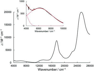 |
| | Fig. 6 UV/vis-NIR absorption spectrum of 1˙+·[SbF6]− in acetonitrile. The inset shows the magnified view of the NIR region. The red solid line shows a fitting curve with two Gaussian functions (dotted and dashed line). | |
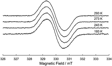 |
| | Fig. 7 Variable-temperature ESR spectrum of 1˙+ in CH2Cl2. | |
According to eqn (1), the V value of 1˙+ in acetonitrile was calculated to be 1871 cm−1. This value is close to that of N,N,N′,N′-tetraanisyl-o-phenylenediamine (1940 cm−1),15 whose radical cation was reported to be an almost delocalized system. Furthermore, the V value of 1˙+ is larger than that of 1,2-bis(N-phenothiazinyl)-4,5-dimethyl-benzene (1280 cm−1),16 probably due to the higher planarity of the DHDAP units than phenothiazines, associated with decreasing the reorganization energy upon the IVCT process in 1˙+.
Isolation of monocationic radical 1˙+
The single crystals of the monocation salt of 1 was obtained by slow diffusion of hexane into a solution of 1˙+·[SbF6]− in acetone, which was prepared by chemical oxidation of 1 using 1 equivalent of AgSbF6. The structure of 1˙+·[SbF6]− was determined by X-ray crystal analysis as shown in Fig. 8. There exists only one crystallographically independent molecule of 1˙+. The 1˙+ cations stack in a face-to-face manner and form one-dimensional columns. The packing structure of 1˙+·[SbF6]− could be characterized as a kind of segregated stack, although [SbF6]− anions were sandwiched by n-hexyl chains of 1˙+ cations, preserving no contacts between SbF6− anions. The four C–N bonds in a DHDAP moiety are expected to become shorter upon one electron removal, judging from the MO pattern of the HOMO. Actually, the average lengths of the four C–N bonds in each DHDAP moiety of 1˙+ are 1.396(2) and 1.403(2) Å, which are shorter than those of neutral 1 (1-A: 1.408(3) and 1.410(2) Å, 1-B: 1.408(3) and 1.410(3) Å) in the crystal. This is suggestive of the positive charge of 1˙+ shared and delocalized by two DHDAP moieties.
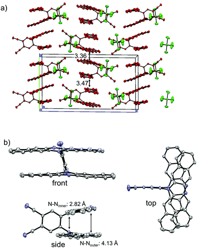 |
| | Fig. 8 X-ray crystal structures of 1˙+·[SbF6]−. (a) Packing structure, (b) structure of 1˙+. The hydrogen atoms, n-hexyl groups, and solvent molecules are omitted for clarity. Thermal ellipsoids are set at 50% probability. | |
Photoconductivity of 1 and 1˙+·[SbF6]−
Encouraged by the charge segregated structure of 1˙+·[SbF6]−, the photoconductive properties of 1 and 1˙+·[SbF6]− were investigated by the flash-photolysis time-resolved microwave conductivity (FP-TRMC) technique.22 In both cases, randomly oriented crystalline samples were used to study the isotropic photoconductive properties of the molecular systems. Fig. 9 shows the FP-TRMC transients for 1 and 1˙+·[SbF6]−. The maximum value of the transient signal of 1 was low (2.4 × 10⁻⁵ cm2 V−1 s−1). This is probably because of the segmented intermolecular π-stacking in the columns of 1 as shown by X-ray crystal analysis. On the other hand, the transient conductivity of the cation salt 1˙+·[SbF6]− was about ten times higher (2.6 × 10⁻⁴ cm2 V−1 s−1) than that of 1 with a very long lifetime of up to milliseconds (τ1/2 ≃ 9 ms). The drastic increase of the photoconductivity of 1˙+·[SbF6]− compared with 1 could be ascribed to the segregated packing structure, which is desirable for charge conduction in charge transfer salts. The remarkably long charge-separation lifetime suggests the long-distance charge delocalization in the one-dimensional column of 1˙+. Actually, 1˙+·[SbF6]− showed a higher transient signal and a longer charge carrier lifetime than those of the ion-based semiconducting material with the charge-segregated structure,23 probably due to the quasi-3/4-filled-band of 1D DHDAP columns of 1˙+·[SbF6]−. The conductivity kinetic trace observed in 1˙+·[SbF6]− does not obey simple second-order or pseudo-first order decay (Fig. 9(a) and Fig. S10, ESI†). Therefore, we tried to analyse the decay profile by considering both first- and second-order decay as follows.24| |  | (2) |
The analytical solution of eqn (2) is given by eqn (3)| |  | (3) |
where ϕ and  are the charge generation efficiency and the sum of the positive and negative charge carrier mobilities,
  is the initial value of
  , k is a first order rate constant, and γ is a second order rate constant (in units of V cm−2, but it can be converted to a normal second-order rate constant k2 in units of cm3 s−1 through
  , where nP is the photon density in units of cm−3), respectively. As shown in Fig. 9b, the observed kinetic trace was well fitted by eqn (3) with fitting parameters of k = 36 s−1 and γ = 4.2 × 10⁴ V cm−2. The obtained second-order rate constant k2 is compared with the Langevin rate, kLg.25 The ratio k2/kLg = γε0εr/(enP) is in the order of 10−7–10−3 by assuming the value of relative permittivity of 1˙+·[SbF6]− of 1 to 104. This remarkably lower k2 value than kLg strongly suggests that the mobile carriers move through the 1D-columns of 1˙+ whereas their charge counterparts exist beside the columns. The first decay components slightly depend on the excitation photon density (Fig. 9d). It should be noted that the decay decelerated upon an increase in the excitation density, making a striking contrast to the second-order bulk recombination of photo-generated charge carriers, which is also supported by the observed constant photo-conductivity maximum (Fig. 9c) against the excitation density. It is probably due to extremely short Onsager distances realised in the present ion-pair system, leading to the free charge carrier in the regime over ∼10−7 s.
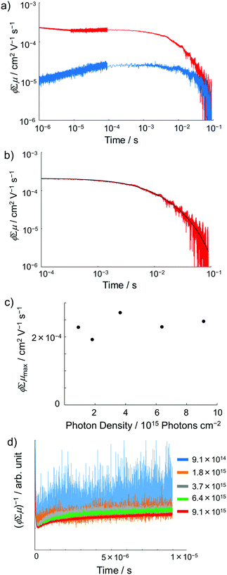 |
| | Fig. 9 (a) FP-TRMC transients of crystalline samples of 1 (blue) and 1˙+·[SbF6]− (red) induced by 355 nm excitation with 9.1 × 10¹⁵ photons cm−2. Each transient curve is represented by a combination of three transient curves measured in different time scales (<10−5 s, 10−5–10−4 s, and 10−4–10−1 s). (b) FP-TRMC transient measured in 10−4–10−1 s time scale (red) and the fitting curve based on eqn (3) (black). (c) Maximum ϕΣμ values of 1˙+·[SbF6]− irradiated with different laser intensities. (d) Laser power dependence of TRMC transients. | |
Conclusions
In conclusion, we have prepared a clip-shaped novel D–A–D triad molecule 1 by nucleophilic addition of 6,13-dihydro-6,13-diazapentacene (DHDAP) derivatives. The absorption, emission, electrochemical measurements revealed the existence of electronic communication between two DHDAP units in 1. The radical cation salt 1˙+·[SbF6]− was isolated as air-stable crystals by chemical oxidation of 1. The cations 1˙+ formed one-dimensional π-stack columns desirable for effective charge conduction. The microwave conductivity measurements showed the much higher photoconductivity of the crystalline 1˙+·[SbF6]− than that of neutral 1. Further attempts of π-conjugated molecular bricolages using azaacenes are in progress.
Instrumentation and materials
All the purchased reagents were of standard quality, and used without further purification. Dry dichloromethane was purchased from Wako Pure Chemical Industry Ltd and dry dimethylformamide was from Kanto Chemical Co., Inc. Column chromatography was performed with silica gel (Kanto Chemical Co., Inc., silica gel 60N, spherical neutral). 1H and 13C NMR spectra were recorded on a JEOL JNM-AL400 FT-NMR spectrometer. Chemical shifts of NMR spectra are determined relative to internal tetramethylsilane (TMS) standard (δ), and are given in parts per million (ppm). Low and high resolution Matrix (MALDI) mass spectra (MS) were obtained on a Bruker ultraflex mass spectrometer with dithranol as a matrix. UV/vis absorption spectra were obtained with a JASCO V-570 spectrometer. UV/vis-NIR absorption spectra were obtained with a Perkin-Elmer Lambda 950 spectrometer. The redox properties were evaluated by cyclic voltammetry (CV) and differential pulse voltammetry (DPV) in CH2Cl2 solution at 298 K with 0.1 M tetra-n-butylammonium tetrafluoroborate (TBABF4) as the supporting electrolyte (scan rate 100 mV s−1) using an ALS/chi Electrochemical Analyzer model 612A. A three-electrode assembly was used, which was equipped with a platinum disk (2 mm2), a platinum wire, and Ag/0.01 M AgNO3 (acetonitrile) as the working electrode, the counter electrode, and the reference electrode, respectively. The redox potentials were referenced against a ferrocene/ferrocenium (Fc0/+) redox potential measured in the same electrolytic solution.
Synthesis of 1
A mixture of 2 (0.190 g, 0.52 mmol) and sodium hydride (60% in oil, 0.02 g, 0.52 mmol) in DMF (5 ml) was stirred under an argon atmosphere at rt for 1.5 h. To the reaction solution, a DMF solution (5 ml) of 4,5-difluorophthalonitrile (0.044 g, 0.27 mmol) was added and stirred for 16 h. The reaction solution was washed with water, and dried over Na2SO4. After evaporation of the solvent, the crude product was chromatographed on silica gel (dichloromethane/hexane = 1![[thin space (1/6-em)]](https://www.rsc.org/images/entities/char_2009.gif) :
:![[thin space (1/6-em)]](https://www.rsc.org/images/entities/char_2009.gif) 2 as eluent) to afford 1 (0.112 g, 49%) as a brown powder. 1H NMR (400 MHz, CDCl3); δ = 1.00 (t, J = 6.83 Hz, 6H), 1.26 (brs, 4H), 1.44 (brs, 8H), 1.60 (brs, 4H), 3.24 (t, J = 7.81 Hz, 4H), 6.12 (s, 4H), 6.16 (s, 4H), 6.67 (d, J = 3.90 Hz, 8H), 6.94–6.98 (m, 4H), 7.11 (d, J = 8.29 Hz, 4H), 8.30 (s, 2H); 13C NMR (100 MHz, CDCl3) δ = 13.95, 22.63, 23.88, 26.50, 31.49, 45.87, 106.13, 106.17, 109.08, 109.16, 114.67, 115.51, 123.39, 123.45, 125.58, 128.45, 131.17, 131.57, 133.28, 142.86; MALDI HRMS (dithranol): m/z calcd for C60H52N6: 856.4248 [M]+; found 856.4239.
2 as eluent) to afford 1 (0.112 g, 49%) as a brown powder. 1H NMR (400 MHz, CDCl3); δ = 1.00 (t, J = 6.83 Hz, 6H), 1.26 (brs, 4H), 1.44 (brs, 8H), 1.60 (brs, 4H), 3.24 (t, J = 7.81 Hz, 4H), 6.12 (s, 4H), 6.16 (s, 4H), 6.67 (d, J = 3.90 Hz, 8H), 6.94–6.98 (m, 4H), 7.11 (d, J = 8.29 Hz, 4H), 8.30 (s, 2H); 13C NMR (100 MHz, CDCl3) δ = 13.95, 22.63, 23.88, 26.50, 31.49, 45.87, 106.13, 106.17, 109.08, 109.16, 114.67, 115.51, 123.39, 123.45, 125.58, 128.45, 131.17, 131.57, 133.28, 142.86; MALDI HRMS (dithranol): m/z calcd for C60H52N6: 856.4248 [M]+; found 856.4239.
TRMC measurement
The photoconductivity of 1 and 1˙+·[SbF6]− upon UV excitation was measured by the flash-photolysis time-resolved microwave conductivity (FP-TRMC) technique at 290 K. A third harmonic generation (λ = 355 nm) of Spectra Physics model INDI-HG Nd:YAG laser pulses was employed as excitation light pulses, operated at 10 Hz with a pulse duration of ca. 5 ns. The photon density of a 355 nm pulse was modulated from 9.1 × 10¹⁴ to 1 × 10¹⁶ photons cm−2 pulse−1. The microwave frequency and power were set at ∼9.1 GHz and 3 mW, respectively, and guided into a microwave cavity. The normalised reflected microwave power (ΔPr/Pr: the ratio of reflected microwave power change) was converted directly into the product of the photocarrier generation yield (ϕ) and the sum of photo-generated electron/hole mobilities  as follows:
where e, A, I0, and Flight are the elementary charge, sensitivity factor (S−1 cm), incident photon density of the excitation laser (photon cm−2), and filling factor (cm−1), respectively. Polycrystalline 1 or 1˙+·[SbF6]− was fixed onto a quartz substrate via polyvinyl alcohol binder, dried under vacuum (∼102 Pa), and loaded into the microwave cavity. The photoconductivity traces were accumulated and averaged over 100 shots.
Conflicts of interest
The authors declare no competing financial interest.
Acknowledgements
This work was supported by a Grant-in-Aid for KAKENHI (17H04874) from the Japan Society for the Promotion of Science (JSPS) and a Grant-in-Aid for Scientific Research on Innovative Areas “π-System Figuration” (26102011). The theoretical calculations were performed using the Supercomputer System of the Research Center for Computational Science in Okazaki (Japan).
Notes and references
-
(a) S. Toyota, Chem. Lett., 2011, 40, 12–18 CrossRef CAS;
(b) S. Toyota, Pure Appl. Chem., 2012, 84, 917–929 CrossRef CAS.
- A. K. Burrell, D. L. Officer, P. G. Plieger and D. C. W. Reid, Chem. Rev., 2001, 101, 2751–2796 CrossRef CAS PubMed.
-
(a) Y. Nakamura, N. Aratani and A. Osuka, Chem. Soc. Rev., 2007, 36, 831–845 RSC;
(b) N. Aratani, D. Kim and A. Osuka, Acc. Chem. Res., 2009, 42, 1922–1934 CrossRef CAS PubMed.
- F. E. Golling, M. Quernheim, M. Wagner, T. Nishiuchi and K. Müllen, Angew. Chem., Int. Ed., 2014, 53, 1525–1528 CrossRef CAS PubMed.
-
(a) U. H. F. Bunz, Pure Appl. Chem., 2010, 82, 953–968 CrossRef CAS;
(b) U. H. F. Bunz, J. U. Engelhart, B. D. Lindner and M. Schaffroth, Angew. Chem., Int. Ed., 2013, 52, 3810–3821 CrossRef CAS PubMed.
- Q. Miao, Synlett, 2012, 326–336 CrossRef CAS.
- D. Sakamaki, D. Kumano, E. Yashima and S. Seki, Angew. Chem., Int. Ed., 2015, 54, 5404–5407 CrossRef CAS PubMed.
-
(a) A. Izuoka, R. Kumai and T. Sugawara, Chem. Lett., 1992, 285–288 CrossRef CAS;
(b) T. Tachikawa, A. Izuoka and T. Sugawara, J. Chem. Soc., Chem. Commun., 1993, 1227–1229 RSC;
(c) T. Tachikawa, A. Izuoka and T. Sugawara, Solid State Commun., 1993, 88, 207–209 CrossRef CAS.
- J. Tanabe, G. Ono, A. Izuoka, T. Sugawara, T. Kudo, T. Saito, M. Okamoto and Y. Kawada, Mol. Cryst. Liq. Cryst., 1997, 296, 61–76 CrossRef CAS.
- M. Chollet, L. Guerin, N. Uchida, S. Fukaya, H. Shimoda, T. Ishikawa, K. Matsuda, T. Hasegawa, A. Ota, H. Yamochi, G. Saito, R. Tazaki, S. Adachi and S. Koshihara, Science, 2005, 307, 86–89 CrossRef CAS PubMed.
- G. I. Csonka, A. Ruzsinszky, J. P. Perdew and S. Grimme, J. Chem. Theory Comput., 2008, 4, 888–891 CrossRef CAS PubMed.
- M. Kasha, H. R. Rawls and M. A. El-Bayoumi, Pure Appl. Chem., 1965, 11, 371–392 CrossRef CAS.
- H. Uoyama, K. Goushi, K. Shizu, H. Nomura and C. Adachi, Nature, 2012, 492, 234–238 CrossRef CAS PubMed.
- W. Huang, T. L. E. Henderson, A. M. Bond and K. B. Oldham, Anal. Chim. Acta, 1995, 304, 1–15 CrossRef CAS.
- G. Nöll and M. Avola, J. Phys. Org. Chem., 2006, 19, 238–241 CrossRef.
- D. Sun, S. V. Rosokha and J. K. Kochi, J. Am. Chem. Soc., 2004, 126, 1388–1401 CrossRef CAS PubMed.
- R. F. Winter, Organometallics, 2014, 33, 4517–4536 CrossRef CAS.
- A. Heckmann and C. Lambert, Angew. Chem., Int. Ed., 2012, 51, 326–392 CrossRef CAS PubMed.
- D. Sakamaki, A. Ito, T. Matsumoto and K. Tanaka, RSC Adv., 2014, 4, 39476–39483 RSC.
- M. Uebe, T. Kazama, R. Kurata, D. Sakamaki and A. Ito, Angew. Chem., Int. Ed., 2017, 56, 15712–15717 CrossRef CAS PubMed.
- M. Renz, K. Theilacker, C. Lambert and M. Kaupp, J. Am. Chem. Soc., 2009, 131, 16292–16302 CrossRef CAS PubMed.
- S. Seki, A. Saeki, T. Sakurai and D. Sakamaki, Phys. Chem. Chem. Phys., 2014, 16, 11093–11113 RSC.
- B. Dong, T. Sakurai, Y. Honsho, S. Seki and H. Maede, J. Am. Chem. Soc., 2013, 135, 1284–1287 CrossRef CAS PubMed.
- H. Oga, A. Saeki, Y. Ogomi, S. Hayase and S. Seki, J. Am. Chem. Soc., 2014, 136, 13818–13825 CrossRef CAS PubMed.
- The Langevin rate was given by kLg = e(ϕΣμ)0/(ϕε0εr), where ε0 and εr are the dielectric permittivity in a vacuum and the relative permittivity, respectively.
Footnote |
| † Electronic supplementary information (ESI) available: X-ray crystallography, spectroscopic and computational data. CCDC 1585082 and 1585083. For ESI and crystallographic data in CIF or other electronic format see DOI: 10.1039/c7qm00563f |
|
| This journal is © the Partner Organisations 2018 |
Click here to see how this site uses Cookies. View our privacy policy here.  *,
Hidenori
Saeki
and
Shu
Seki
 *
*


![[thin space (1/6-em)]](https://www.rsc.org/images/entities/char_2009.gif) 500 cm−1 (570 nm) and a broad band around 13
500 cm−1 (570 nm) and a broad band around 13![[thin space (1/6-em)]](https://www.rsc.org/images/entities/char_2009.gif) 200 cm−1 (760 nm) corresponding to the absorption of the radical cation of the DHDAP unit. Furthermore, 1˙+ also showed broad absorption in the NIR region extending from 10
200 cm−1 (760 nm) corresponding to the absorption of the radical cation of the DHDAP unit. Furthermore, 1˙+ also showed broad absorption in the NIR region extending from 10![[thin space (1/6-em)]](https://www.rsc.org/images/entities/char_2009.gif) 500 cm−1 (950 nm) to lower than 4000 cm−1 (2500 nm), which could be attributed to the intervalence transfer (IV) or charge resonance (CR) band between the two DHDAP units via through-bond and through-space pathways.19,20 Unfortunately, it was impossible to evaluate the electronic coupling experimentally from the position and the shape of the lowest energy band because most of the lowest energy band is out of the range of our measurement system. However, the NIR spectral shape was well fitted by superposition of two Gaussian functions with peaks at 6127 and 3742 cm−1. TD-DFT calculations of 1′˙+ at the UB3LYP/6-31G(d) level using the optimized geometry with the UM06-2X/6-31G(d) level qualitatively reproduced the observed double peak feature (Fig. S7, ESI†). Again the TD-DFT calculation was also performed with the condition recommended by Kaupp and co-workers for application to IVCT systems using the BLYP-based hybrid functional with 35% exact exchange and the SVP basis.21 The latter calculation protocol with Kaupp's condition gave better reproduction of the observed NIR absorption spectral shape (Fig. S8, ESI†), and the lowest energy transition was attributed to the CR transition in the stacked DHDAP moieties in both cases (Table S5 and S6, ESI†). To obtain further information about charge/spin dynamics, we also measured the variable-temperature ESR spectra of 1˙+. The solution of 1˙+ showed a broad structureless spectrum at 293 K due to the hyperfine interactions from a number of hydrogen and nitrogen nuclei. The spectral shape remained unchanged upon decreasing the temperature to 193 K (Fig. 7), suggesting that 1˙+ could be classified as a valence-delocalized class III or at the borderline of class II/III in the Robin-Day classification. Assuming that 1˙+ is a class III system, the electronic coupling element (V) of 1˙+ is simply obtained by eqn (1).
500 cm−1 (950 nm) to lower than 4000 cm−1 (2500 nm), which could be attributed to the intervalence transfer (IV) or charge resonance (CR) band between the two DHDAP units via through-bond and through-space pathways.19,20 Unfortunately, it was impossible to evaluate the electronic coupling experimentally from the position and the shape of the lowest energy band because most of the lowest energy band is out of the range of our measurement system. However, the NIR spectral shape was well fitted by superposition of two Gaussian functions with peaks at 6127 and 3742 cm−1. TD-DFT calculations of 1′˙+ at the UB3LYP/6-31G(d) level using the optimized geometry with the UM06-2X/6-31G(d) level qualitatively reproduced the observed double peak feature (Fig. S7, ESI†). Again the TD-DFT calculation was also performed with the condition recommended by Kaupp and co-workers for application to IVCT systems using the BLYP-based hybrid functional with 35% exact exchange and the SVP basis.21 The latter calculation protocol with Kaupp's condition gave better reproduction of the observed NIR absorption spectral shape (Fig. S8, ESI†), and the lowest energy transition was attributed to the CR transition in the stacked DHDAP moieties in both cases (Table S5 and S6, ESI†). To obtain further information about charge/spin dynamics, we also measured the variable-temperature ESR spectra of 1˙+. The solution of 1˙+ showed a broad structureless spectrum at 293 K due to the hyperfine interactions from a number of hydrogen and nitrogen nuclei. The spectral shape remained unchanged upon decreasing the temperature to 193 K (Fig. 7), suggesting that 1˙+ could be classified as a valence-delocalized class III or at the borderline of class II/III in the Robin-Day classification. Assuming that 1˙+ is a class III system, the electronic coupling element (V) of 1˙+ is simply obtained by eqn (1).![[small nu, Greek, tilde]](https://www.rsc.org/images/entities/i_char_e0e1.gif) max/2
max/2

 are the charge generation efficiency and the sum of the positive and negative charge carrier mobilities,
  is the initial value of
  , k is a first order rate constant, and γ is a second order rate constant (in units of V cm−2, but it can be converted to a normal second-order rate constant k2 in units of cm3 s−1 through
  , where nP is the photon density in units of cm−3), respectively. As shown in Fig. 9b, the observed kinetic trace was well fitted by eqn (3) with fitting parameters of k = 36 s−1 and γ = 4.2 × 10⁴ V cm−2. The obtained second-order rate constant k2 is compared with the Langevin rate, kLg.25 The ratio k2/kLg = γε0εr/(enP) is in the order of 10−7–10−3 by assuming the value of relative permittivity of 1˙+·[SbF6]− of 1 to 104. This remarkably lower k2 value than kLg strongly suggests that the mobile carriers move through the 1D-columns of 1˙+ whereas their charge counterparts exist beside the columns. The first decay components slightly depend on the excitation photon density (Fig. 9d). It should be noted that the decay decelerated upon an increase in the excitation density, making a striking contrast to the second-order bulk recombination of photo-generated charge carriers, which is also supported by the observed constant photo-conductivity maximum (Fig. 9c) against the excitation density. It is probably due to extremely short Onsager distances realised in the present ion-pair system, leading to the free charge carrier in the regime over ∼10−7 s.

![[thin space (1/6-em)]](https://www.rsc.org/images/entities/char_2009.gif) :
:![[thin space (1/6-em)]](https://www.rsc.org/images/entities/char_2009.gif) 2 as eluent) to afford 1 (0.112 g, 49%) as a brown powder. 1H NMR (400 MHz, CDCl3); δ = 1.00 (t, J = 6.83 Hz, 6H), 1.26 (brs, 4H), 1.44 (brs, 8H), 1.60 (brs, 4H), 3.24 (t, J = 7.81 Hz, 4H), 6.12 (s, 4H), 6.16 (s, 4H), 6.67 (d, J = 3.90 Hz, 8H), 6.94–6.98 (m, 4H), 7.11 (d, J = 8.29 Hz, 4H), 8.30 (s, 2H); 13C NMR (100 MHz, CDCl3) δ = 13.95, 22.63, 23.88, 26.50, 31.49, 45.87, 106.13, 106.17, 109.08, 109.16, 114.67, 115.51, 123.39, 123.45, 125.58, 128.45, 131.17, 131.57, 133.28, 142.86; MALDI HRMS (dithranol): m/z calcd for C60H52N6: 856.4248 [M]+; found 856.4239.
2 as eluent) to afford 1 (0.112 g, 49%) as a brown powder. 1H NMR (400 MHz, CDCl3); δ = 1.00 (t, J = 6.83 Hz, 6H), 1.26 (brs, 4H), 1.44 (brs, 8H), 1.60 (brs, 4H), 3.24 (t, J = 7.81 Hz, 4H), 6.12 (s, 4H), 6.16 (s, 4H), 6.67 (d, J = 3.90 Hz, 8H), 6.94–6.98 (m, 4H), 7.11 (d, J = 8.29 Hz, 4H), 8.30 (s, 2H); 13C NMR (100 MHz, CDCl3) δ = 13.95, 22.63, 23.88, 26.50, 31.49, 45.87, 106.13, 106.17, 109.08, 109.16, 114.67, 115.51, 123.39, 123.45, 125.58, 128.45, 131.17, 131.57, 133.28, 142.86; MALDI HRMS (dithranol): m/z calcd for C60H52N6: 856.4248 [M]+; found 856.4239.
 as follows:


