DOI:
10.1039/C7QI00590C
(Research Article)
Inorg. Chem. Front., 2018,
5, 127-138
Photocatalytic activity of Hemin (Fe(III) porphyrin) anchored BaTiO3 under the illumination of visible light: synergetic effects of photosensitization, photo-Fenton & photocatalysis processes†
Received
22nd September 2017
, Accepted 20th October 2017
First published on 23rd October 2017
Abstract
The photocatalytic activity of Hemin (Fe(III) porphyrin) anchored BaTiO3 (HBTO) under the illumination of visible light was studied. The average crystallite sizes obtained from PXRD were 42.88 nm and 40.32 nm for BaTiO3 (BTO) and HBTO, respectively. The higher lattice strain values for the HBTO photocatalyst confirms the anchoring of hemin on BTO. The interaction of carboxylate groups of the hemin molecule with –OH groups, which are invariantly present on the surface of BTO through O–C–O–Ti bond, was confirmed by FTIR study. The observed XPS shift in the binding energy values of HBTO can be attributed to the anchoring of the hemin molecule to metal ions as well as due to the interaction with delocalized π-electrons of the porphyrin moiety. HBTO showed 33% decrease in the photoluminescence emission, implying less recombination of photogenerated charge carriers. This could be due to the efficiency of non-radiative electron-transfer through ISC from the excited singlet to the triplet state in the case of HBTO. The synergetic effects of various processes like photosensitization, formation of reactive singlet oxygen and the redox reactions involving iron in the +2 and +3 oxidation states were responsible for the extensive photonic efficiency of HBTO particularly in the presence of H2O2.
1. Introduction
The exploration of new catalysts with suitable band gaps for absorbing visible light has aroused significant interest around the world. In this context, wide bandgap materials are a class of compounds, which are quite promising since they are most stable in aqueous media and have the potential to drive the desired photochemical reactions.1–3 However, these materials are poor absorbers of visible light. In the present study, we selected BaTiO3, a well-known perovskite type bi-metallic oxide with a bandgap energy >3 eV, which has been explored to a lesser extent for photocatalytic activity [4]. However, BaTiO3 is active only under ultraviolet (UV) light irradiation, due to its wide bandgap energy. The intrinsic performance of the photocatalyst was reduced to a certain extent due to the high rate of charge carrier recombination and the literature shows several attempts that have been made by researchers to modify the surface to reduce the recombination.4,5 In the present study an attempt has been made to anchor an inorganic porphyrin metal complex molecule on the surface of the BaTiO3 photocatalyst in order to reduce the recombination of photogenerated charge carriers and also to extend its response to the visible region.
Porphyrins are highly conjugated complex molecules that are of various types such as metal-free porphyrins, metalloporphyrins and supramolecular porphyrins.6 These porphyrins have been well recognized as the most promising sensitizers in order to harvest visible light, since they are structural analogues of the chlorophyll in plants.7 They are highly effective moieties for enhancing photocatalytic activity due to their strong absorption at around 400–450 nm (Soret band) and around 500–700 nm (Q bands). In addition, the presence of π-electrons in these highly conjugated complexes facilitates smooth electron transfer during the photoreaction. Some porphyrins are extensively used in the thermal catalytic oxidation reactions, since they can efficiently activate molecular O2.8 Among the known porphyrins, hemin is a natural metalloporphyrin complex (protoporphyrin IX Fe(III)) that exhibits excellent electrocatalytic properties for the detection of many analytes.9 In addition, it is used as an electron mediator due to its ability to exist in reversible redox states of Fe(III)/Fe(II). Reports have also shown that metal complexes of porphyrins are highly photostable when adsorbed on the metal oxide photocatalyst surfaces and can be efficiently used in environmental remediation processes.10 To the best of our knowledge, the photocatalytic performance of hemin anchored BaTiO3 has never been explored. This research demonstrates the role of the hemin molecule in extending the light absorption response of BaTiO3 to the visible region for the degradation of 4-chlorophenol (4-CP) as the model compound.
2. Experimental section
2.1. Materials
Analytical grade titanium(IV) chloride (TiCl4 ≥ 99.9%), hemin and acetonitrile were obtained from Merck Chemicals Limited. Barium chloride and oxalic acid dihydrate were obtained from British Drug House (India) Pvt. Limited. 4-CP and dimethyl sulfoxide were obtained from SD Fine Chemicals. Hydrogen peroxide (H2O2) (30% w/v) was obtained from Sisco-Chemical Industries. ter-Butanol (TBA) was obtained from Qualigens Fine Chemicals, and ethylene diamine tetra-acetic acid (EDTA) was obtained from Sigma Aldrich. Double distilled water was used for all the experiments.
2.2. Preparation of BaTiO3 (BTO) catalyst
BaTiO3 was prepared by the sol–gel method using diluted TiCl4 and BaCl2.11 The concentrated TiCl4 solution was diluted and its titanium content was determined. To an aliquot solution containing 6.5 g of titanium, a solution containing 32 g of BaCl2·2H2O dissolved in 320 mL of water was added. This abovementioned mixture was added dropwise to a hot (80 °C), well-stirred solution of oxalic acid (37 g of dihydrate salt dissolved in 320 mL of water). A crystalline precipitate of barium titanyl oxalate was obtained. This precipitate was washed several times to remove all the chloride ions and was further air-dried. The obtained barium titanyl oxalate was calcined at 700 °C for 4 h to obtain BaTiO3 (BTO).
2.3. Preparation of hemin anchored BaTiO3 (HBTO)
1 g sample of BTO was suspended in 5 μM hemin solution (at pH 4). The hemin solution was made in 1![[thin space (1/6-em)]](https://www.rsc.org/images/entities/char_2009.gif) :1 mixture of dimethyl sulfoxide and acetonitrile (DMSO/CH3CN). The HBTO sample was dried at room temperature until the solvent was completely evaporated.12
:1 mixture of dimethyl sulfoxide and acetonitrile (DMSO/CH3CN). The HBTO sample was dried at room temperature until the solvent was completely evaporated.12
2.4. Instruments used for the characterisation of the catalyst
The powder X-ray diffraction (PXRD) patterns were obtained using a Panalytical X'pert Pro MPD diffractometer, which was operated at 30 kV and 20 mA using a Cu Kα source with nickel filter. The scan rate was varied from 2° to 0.5° min−1 to obtain X-ray diffraction line broadening. The Fourier transform infrared (FTIR) spectra were obtained using a Thermo Avtar 370 spectrometer with KBr as the standard. The Diffuse Reflectance Spectra (DRS) of the photocatalyst were obtained using a UV-Visible spectrophotometer (Shimadzu-UV 3101 PC UV-VIS-NIR) with BaSO4 as the reference standard. The surface morphology was analysed by scanning electron microscopy (SEM), using an ULTRA 55 microscope operating at 25 kV. The nitrogen adsorption–desorption isotherms were recorded on a Nova Quanta Chrome Corporation 2006 Digisorb analyser at liquid Nitrogen temperature of 77 K. The X-ray photoelectron spectroscopy (XPS) measurements were carried out using AXIS ULTRA from AXIS 165, integrated with Kratos patented magnetic immersion lens, a charge neutralization system and spherical mirror analyser. The photoelectrochemical studies were performed using CH Instruments Inc. 620B electrochemical workstation. The photoluminescence (PL) spectra were measured on a Hitachi F-7000 fluorescence spectrophotometer. The reaction intermediates during the course of the degradation reaction were analysed by a gas chromatography-mass spectrometry (GC-MS) technique using a Thermo Trace GC Ultra, MS model Thermo DSQ II accompanied by electron impact ionisation and the chemical ionisation techniques/modes with mass range of 1–1071 m/z. GC-MS spectra were recorded for the degradation experiments; the test samples were collected at different time intervals and were extracted into non-aqueous chloroform solvent (10 mL of reaction mixture was extracted in 5 mL of chloroform. Further, the test solution was concentrated by evaporating the chloroform in a rotavaporizer. 1 μL of this sample was injected into the GC-MS system). Pure helium was used as the carrier gas at the flow rate of 1.2 mL min−1. The injector, transfer line, and trap temperatures were maintained at 220 °C, 250 °C, and 200 °C, respectively. Electron impact ionization was carried out at 70 eV.
2.5. Photochemical reactor and photonic efficiency (ϕλ)
Experiments were carried out under solar light illumination from 11 a.m. to 2 p.m. The average sunlight intensity was found to be around 0.753 kW m−2 (using a solar radiometer). The intensity of the solar light was focused and concentrated by using a convex lens and the reaction mixture was exposed to this light. The experimental solution (250 mL) was taken in a circular glass reactor whose surface area was 176.6 cm2 and the solution was continuously stirred (100 rpm) for entire time span of the reaction. To compare the photocatalytic activity of different catalysts, the experiments were conducted simultaneously. The residual concentrations of the substrate 4-CP pollutant molecule was monitored by collecting samples at different time intervals and they were analysed by UV-visible and GC-MS spectroscopic techniques.
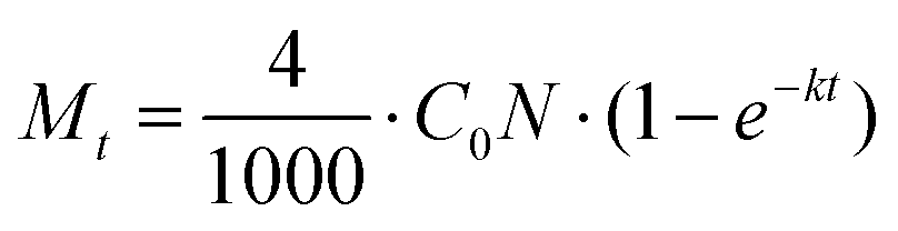
The photonic efficiencies (ϕλ) were calculated by the method proposed by Tsoukleris et al.13 by using the ratio of the rate of degradation of the 4-CP molecule (Mt) with respect to the total rate of incident photons (L):
The rate of degradation is given by the number of pollutant molecules decomposing in a given time (t), which can be calculated using the following equation:
where
C0 is the initial concentration of the pollutant,
N is Avogadro's number and
k is the first-order reaction rate constant.
The total rate of incident photons in the given time (t) is given by
where
p is the power of the light,
λ is the wavelength,
h is Planck's constant and
c is the velocity of light in the vacuum. Photocurrent measurements were made under both UV and solar light irradiation. Medium pressure mercury vapor lamp (125 W) was used as the UV light source for the photocurrent measurements. Photon flux of the UV light source (the wavelength of which is around 370 nm) was found to be 7.8 mW cm
−2 by ferrioxalate actinometry.
2.6. Photoelectrochemical set up
The photoelectrochemical reaction experiments were performed in an aqueous electrolytic solution of sodium nitrate (Na2NO3, 0.1 M, 250 mL) containing a three electrode system. Glassy carbon electrode, Pt electrode and a saturated calomel electrode were employed as the working electrode, counter-electrode and reference electrode, respectively. The photocatalyst (300 mg) was dispersed in the electrolytic solution. The response of the photocurrent for each photocatalyst was measured under UV/solar light irradiation. The time interval between the light-on and light-off cycles was 10 s.
3. Results and discussion
3.1. PXRD studies
Fig. 1 shows the PXRD patterns of BTO and HBTO. Both samples show peaks corresponding to the tetragonal phase of BTO and the peaks at different 2θ values along with the corresponding hkl values are as follows: 22.17° (100), 31.59° (101), 39.07° (111), 45.30° (200), 50.92° (210), 56.32° (211), 65.86° (220), 70.52° (212), 75.06° (310), and 79.22° (311); these values are comparable to the standard values (JCPDS file no. 75-2120). The average crystallite size was estimated based on the broadening of the (101) peak at 2θ = 31.625° using Scherrer's equation:
| D = kλ/βcosθ |
where λ is the wavelength of the Cu Kα source used (λ = 1.541 Å), β is the full width at half maximum (FWHM) of the (101) diffraction plane, k is the shape factor (0.94) and θ is the angle of diffraction. The average crystallite size values were found to be 42.88 nm and 40.32 nm for BTO and HBTO, respectively. This slight decrease in crystallite size for HBTO could lead to a marginal increase in the surface area of the photocatalyst. The lattice strain (ε) was calculated from the following equation:
| ε = β/4tanθ |
where β is the FWHM of the (101) diffraction plane and θ is the angle of diffraction as mentioned earlier. The calculated lattice strain values were found to be 2.97 × 10⁻³ and 3.26 × 10⁻³ for BTO and HBTO samples, respectively (Table 1). The surface deposition of hemin on BTO slightly shifted the 100% peak towards higher 2θ value as shown in the PXRD patterns. Further, an increase in the lattice strain value was observed upon surface deposition of hemin. It was also observed that the crystallite size, lattice parameters and cell volume slightly decreased in the case of the HBTO sample compared to BTO.
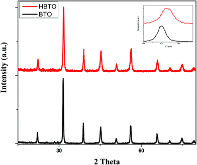 |
| | Fig. 1 PXRD pattern of BTO and HBTO. | |
Table 1 Specification of phase, crystallite size, lattice parameters, cell volume and lattice strain values for BTO and HBTO samples
| Sample |
Phase |
D (nm) |
A (Å) |
V (Å)3 |
ε × 10−3 |
|
D = crystallite size; A = lattice parameters in Å; V = unit cell volume in (Å)3, ε = lattice strain. |
| BTO |
Tetragonal |
42.88 |
a = b = 3.954 |
62.63 |
2.97 |
|
c = 4.006 |
| HBTO |
Tetragonal |
40.32 |
a = b = 3.892 |
60.62 |
3.26 |
|
c = 4.002 |
3.2. UV-Visible absorbance spectral studies
The UV-Visible absorption spectra of BTO and HBTO are shown in Fig. 2. The surface deposition of hemin, a highly conjugated molecule on the BTO sample, extended the photoresponse of the sample to the visible light region. It was observed that pure BTO exhibits a strong absorption only in the UV region due to the charge-transfer process from oxygen 2p orbitals of the valence band to the titanium 3d orbitals of the conduction band at a wavelength of 395 nm.14 In the case of HBTO, the absorption curve was characterized by a Soret band at ∼430 nm, which is observed more clearly under slow scanning condition. The band gap energies were calculated using the formula Eg = 1240/λ, where λ is the absorption wavelength of the catalyst. The absorption wavelength of HBTO was at 500 nm. The calculated bandgap values of BTO and HBTO were found to be 3.14 eV and 2.48 eV, respectively. The shift in absorption for HBTO occurred due to the delocalization of π-electrons in the highly conjugated porphyrin ring of hemin as well as due to the interaction of carboxylate groups of the hemin molecule with the –OH groups that are invariantly present on the surface of BTO.12 The observed absorption bands between 550–650 nm in the case of HBTO are attributed to the Q-band, which is the characteristic feature of the hemin molecule.15,16 The absorption spectral results confirm the presence of anchored hemin molecules on the surface of BTO.
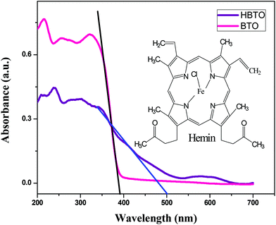 |
| | Fig. 2 UV-Vis absorbance spectra of BTO and HBTO; the inset shows the structure of the hemin molecule. | |
3.3. FTIR analysis
FTIR analysis was used to investigate the nature of interaction between hemin molecules with BTO nanoparticles. Fig. 3 shows the FTIR spectra of BTO and HBTO in the range of 500–4000 cm−1. A broad band corresponding to the Ti–O stretching was observed at approximately 570 cm−1 for both the samples.17 Another broad band observed at 735 cm−1 was due to the stretching vibrations of bridged Ti–O bonds. The spectrum of HBTO shows a split peak around 1580–1400 cm−1 corresponding to the C![[double bond, length as m-dash]](https://www.rsc.org/images/entities/char_e001.gif) O vibrations of the surface bound carboxylic acid group and hydrogen bonded carboxylic acid, respectively.18 Another small peak observed at 1068 cm−1 was due to the stretching modes of the C–N group present in the hemin moiety. The peaks observed at 3480 cm−1 and 1640 cm−1 confirm the presence of the uncoordinated –COOH group and the hydrogen bonded –COOH group of the hemin molecule (Fig. S1†).18 An FTIR study confirmed the binding of the hemin molecule on the BTO surface through the O–C–O–Ti bond.
O vibrations of the surface bound carboxylic acid group and hydrogen bonded carboxylic acid, respectively.18 Another small peak observed at 1068 cm−1 was due to the stretching modes of the C–N group present in the hemin moiety. The peaks observed at 3480 cm−1 and 1640 cm−1 confirm the presence of the uncoordinated –COOH group and the hydrogen bonded –COOH group of the hemin molecule (Fig. S1†).18 An FTIR study confirmed the binding of the hemin molecule on the BTO surface through the O–C–O–Ti bond.
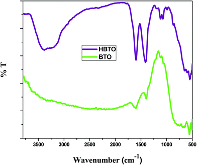 |
| | Fig. 3 FTIR spectrum of BTO and HBTO samples. | |
3.4. Surface morphology of BTO and HBTO
The surface morphology of BTO and HBTO samples were identified from the SEM images as shown in Fig. 4. The morphology of the catalysts is found to be spherical agglomerates. The morphology of hemin is also highly distinguishable spheres (as found from the ref. 19). It could be observed that the anchoring of the hemin molecule did not alter the morphology of the catalyst. The size of the nanoparticles are in the range 10–70 nm with an average particle size between 30–40 nm; the particle size distribution of BTO and HBTO are shown in the Fig. 5a and b.
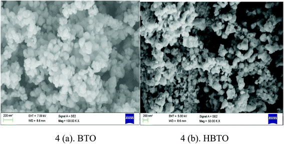 |
| | Fig. 4 SEM images of BTO and HBTO. | |
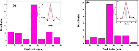 |
| | Fig. 5 (a & b) Particle size distribution of BTO and HBTO. | |
3.5. BET surface area studies
The N2 adsorption–desorption isotherm of the BTO and HBTO with their corresponding pore size distribution profiles are shown in Fig. 6. The pore size distribution was calculated from desorption branch of a nitrogen isotherm by the Barrett–Joyner–Halenda (BJH) method.20 The mesoporous structure of the catalysts was confirmed by N2 gas sorption, which shows the type-IV adsorption isotherm with an elongated hysteresis.21 The hysteresis loop occurs in the p/p0 range of 0.6417–0.9729 for BTO and 0.5611–0.9817 for HBTO. The specific surface area, pore diameter and pore volume of the samples were calculated from the N2 isotherms and the values are listed in Table 2. The measured pore size distribution indicates a pronounced mesoporosity and higher specific surface area for HBTO, compared to BTO. The pore size distribution curve was obtained from the desorption branch of the isotherm by the BJH method. It was observed that there was a decrease in the average pore diameter and an increase in the specific surface area for the HBTO photocatalyst.
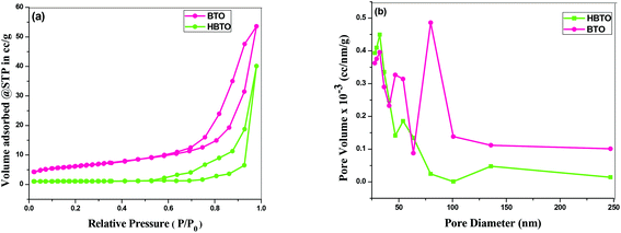 |
| | Fig. 6 (a) The N2 adsorption–desorption isotherms; (b) BJH pore size distribution curves of BTO and HBTO. | |
Table 2 The BET surface area, pore volume and pore diameter of BTO and HBTO photocatalysts
| Photocatalyst |
BET surface area (m2 g−1) |
Pore volume (cm3 g−1) |
Pore diameter (nm) |
| BTO |
16.28 |
0.489 |
18.36 |
| HBTO |
32.42 |
0.183 |
12.52 |
3.6. XPS studies
The XPS technique was used to analyze the different oxidation states and chemical environments of the ions in the compounds. The XPS survey scan of the HBTO photocatalyst showed trace amounts of the presence of Fe 2p (710 eV), C 1s (284 eV) and N 1s (400 eV) peaks, which confirm the presence of the hemin molecule and the surface modification of BTO. The 3d binding energy (BE) of the Ba doublet peak values (Fig. 7a) are located at 795.7 eV and 780.29 eV, which could be ascribed to the splitting of Ba 3d3/2 and Ba 3d5/2 spin states in the BTO sample, respectively.22 These peaks appear at slightly lower BE values of 794.4 eV and 779 eV for HBTO. The BE values of Ti 2p3/2 and Ti 2p1/2 were observed at 459.31 eV and 464.52 eV for BTO (Fig. 7b) and were located at 458.9 eV and 464.16 eV for HBTO, respectively.23 The observed shifts for the HBTO sample can be attributed to the anchoring of the hemin molecule on the metal ions as well as due to the interaction with the delocalized π-electrons of the porphyrin moiety. Further, this interaction between the carboxyl groups of hemin and the surface Ti ions leads to the formation of C–O–Ti bonds. Therefore, the carboxylate group serves as an interlocking entity, enhancing the electronic coupling between the π* orbitals of the porphyrin with the Ti (3d) orbitals. The energy of the π* molecular orbital of the porphyrin is decreased by this delocalization, which is evident in the shift of the binding energy peaks.24 The O 1s XPS spectra of BTO consists of a single peak observed at 530.37 eV, which is due to the oxygen (O–Ti–O) in the crystal lattice. The HBTO shows three peaks: the first BE peak at 530.71 eV is related to oxygen bonded to the Ti metal ion as O–Ti–O; the second peak at 529.73 eV can be assigned to oxygen linked with Ba and Ti (Ba–O–Ti) (Fig. 7c); the third low intensity peak at 533 eV can be assigned to the oxygen of Ti–O–C bond.25 In addition to these peaks, the presence of C 1s, N 1s and Fe 2p in the HBTO sample further confirms the successful anchoring of hemin on the BTO surface. Fig. 7d shows the C 1s region. The BE values of carbon bonded to different ions show very small peak intensities at 284 eV (C–C), 285 e V (C–N), 286.4 eV (C–O), 287.9 eV (CO) and 288.9 eV (O–CO). The N 1s spectrum (Fig. 7e) with a BE peak at 398.8 eV is ascribed to the four chemically equivalent N atoms that are bonded to the central iron atom in the porphyrin ring.26 The XPS spectra of Fe 2p (Fig. 7f) shows three BE peaks at 705.9 eV (Fe 2p3/2), 716.9 eV (Fe 2p1/2), and a satellite peak at 712.17 eV (Fe 2p3/2). The BE peak positions of Fe 2p3/2 are usually expected to be found between 710.6 and 711.2 eV, but in the present case, the observed shift (∼5 eV) in its position for the HBTO sample suggests a strong interaction of hemin molecule with BTO.27
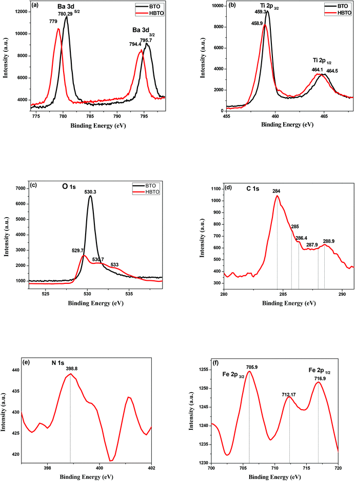 |
| | Fig. 7 XPS spectra of (a) Ba 3d; (b) Ti 2p; (c) O 1s of BTO and HBTO samples. XPS spectra of (d) C 1s; (e) N 1s & (f) Fe 2p of the HBTO sample. | |
3.7. Photoluminescence (PL) studies
The PL is a multiphonon process and emission occurs from different states within the band gap of the semiconductor due to the recombination process. Therefore, PL spectra can be used to study the efficiency of charge carrier trapping, their migration and also the fate of photogenerated electron–hole pairs in the semiconductors.28,29 This technique is also used to assess the presence of surface states, efficiency of charge carrier trapping and their recombination kinetics in the semiconductors.30 The charge carriers recombine rapidly to provide photoluminescence emission and the intensity of this emission is proportional to the extent of electron–hole pair recombination under the light illumination. The wavelength of the excitation was at 320 nm. The PL emission spectra (Fig. 8) show a strong band below 400 nm, which could be attributed to the charge transfer process from the VB (oxygen 2p orbitals) to the CB (titanium 3d orbitals). The observed emission is due to the recombination, corresponding to the charge transfer from the central titanium ion to a neighboring oxygen ion within the TiO68− octahedron.31 This peak is observed for both BTO and HBTO samples. This peak at 400 nm is of lower intensity for the HBTO sample, implying a lower rate of recombination of photogenerated charge carriers, compared to BTO. HBTO shows 33% decrease in this emission, indicating the possibility of a non-radiative electron transfer process taking place by the fast intersystem crossing from the excited singlet to the triplet state.32 The obtained PL data confirm the interaction between metal oxide and porphyrin. The delocalized π-electrons in the porphyrin ring could interact with the carboxylate groups of hemin, which could give rise to a peak at 454 nm in the bare hemin sample. In the case of HBTO, due to the complex formation between hemin and BTO, this peak is shifted to 470 nm. However, the BTO sample also shows a peak at 470 nm, which could be due to the recombination involving the defects of the neutral oxygen vacancies (νo), singly/doubly ionized oxygen vacancies  , non-centrosymmetric Ti3+ state associated with oxygen vacancy (Ti3+-νo) and intrinsic structural defects, which are responsible for the PL emission at 470 nm. Therefore, the peak at 470 nm can account for both recombination reactions occurring due to the presence of the abovementioned defects in BTO and also due to the presence of hemin in HBTO. This peak intensity is considerably decreased for HBTO, since the hemin moiety provides free channels of the type OC–O–Ti bonds through which the electron can migrate and the recombination is hindered to a certain extent.
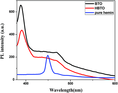 |
| | Fig. 8 PL spectra of BTO, HBTO and hemin. | |
3.8. Photoelectrochemical studies
Photoelectrochemical studies were carried out using BTO and HBTO samples under UV/solar light illumination (Fig. 9). Photocurrent generation can be correlated to the photocatalytic activity of the catalyst samples. The higher the current, the higher will be the photocatalytic activity. This measurement was employed to elucidate the process of charge separation and the charge transfer dynamics of photogenerated charge carriers under the influence of the electric field. The magnitude of the observed photocurrent is higher for HBTO under both UV and solar light irradiation, compared to BTO. BTO could not be excited under visible light irradiation due to its large band gap. The observed photocurrent for HBTO under visible light is due to the charge transfer process from the excited hemin moiety to the CB of BTO. The higher magnitude of photocurrent for HBTO as compared to BTO indicates the efficient charge transfer process. Separation efficiency was improved due to the electronic interaction between the hemin molecule and BTO. The photogenerated electrons can migrate from BTO to the highly conjugated hemin molecule under UV irradiation, thereby prolonging the life time of the electron. These electrons are expected to move in the external circuit to generate photocurrent. This movement of electrons is more efficient for the HBTO sample, generating higher photocurrent. The magnitude of photocurrent was tested for several light on and off repetitions and it was observed to be constant, indicating the stability of the catalyst in the reaction medium.
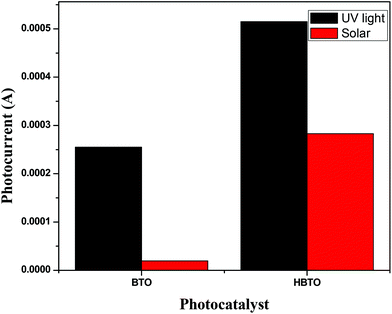 |
| | Fig. 9 The magnitude of photocurrent measurements for BTO and HBTO photocatalysts. | |
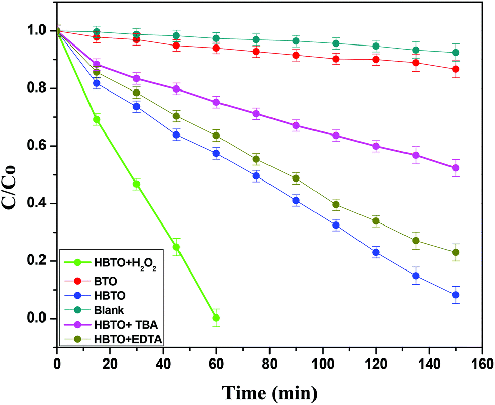
4. Photocatalytic activity
The photocatalytic activities of BTO and HBTO were evaluated for the degradation of 4-CP under solar light irradiation (Fig. 10). The activity of BTO under visible light irradiation was limited due to its higher band gap. The values of the rate constant (k), photonic efficiency (ϕλ) and the percentage degradation under different reaction conditions for these catalysts were evaluated (Table 3). The main active oxidative species (hydroxyl free radicals and holes) responsible for the degradation process were indirectly identified through the trapping experiments conducted using TBA (hydroxyl free radical scavenger) and EDTA (hole scavenger). The crucial reaction pathways that occur in this system can be specified in the following manner:
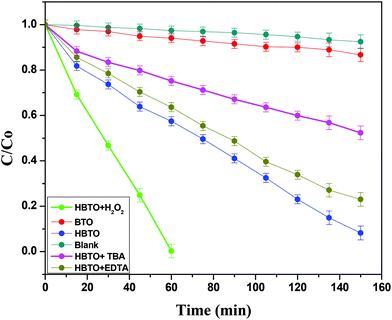 |
| | Fig. 10 Plot of C/C0versus time for the degradation of 4-CP with solar light illumination under different experimental conditions. | |
Table 3 Rate constant, photonic efficiency and % degradation of 4-CP under solar light illumination
| Photocatalyst |
k × 10−2 min−1 |
Time (min) |
% Degradation |
ϕ
λ
× 10−8 mol L−1 m2 |
|
k = rate constant, ϕλ = photonic efficiency. |
| BTO |
0.010 |
150 |
13.35 |
0.021 |
| HBTO |
0.096 |
150 |
91.79 |
0.123 |
| HBTO + TBA |
0.039 |
150 |
47.69 |
0.050 |
| HBTO + EDTA |
0.090 |
150 |
87.21 |
0.115 |
| HBTO + H2O2 |
8.423 |
60 |
100 |
10.842 |
| Blank |
0.005 |
150 |
7.51 |
0.006 |
4.1. Role of hemin as a sensitizer
Under solar light irradiation, the ground state hemin molecule of HBTO gets excited to form the singlet state (HBTO*) through one photon transition.33 The photogenerated electrons readily get injected into the CB (of BTO), leading to the photosensitization process, and subsequently get transferred to either surface oxygen molecules (electron is trapped by the triplet oxygen to form reactive singlet oxygen) or can react with water to yield superoxide and hydroxyl free radicals, which would oxidize 4-CP. Simultaneously, the holes in the valence band (VB) of hemin can react with either the hydroxyl anion or with water molecules, leading to the formation of hydroxyl free radicals. Further, the oxidized HBTO+ molecule in turn gets reduced possibly by water molecules or by the 4-CP molecule to its ground state.34 The equations are summarised as follows:| | 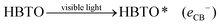 | (1) |
| | | HBTO* (eCB−) + O2 → HBTO+ + O2˙− | (2) |
| | | HBTO+ + OH− → HBTO + OH˙ | (3) |
| | | O2˙− + 4-CP → oxidation products | (4) |
| | | OH˙ + 4-CP → oxidation products | (5) |
In general, porphyrins show strong absorption in the visible region due to the presence of the extensive conjugation system along with its delocalized π-electrons; also, they are excellent photosensitizers due to inter system crossing (ISC) ability with small singlet–triplet splitting energy and long triplet state life time.35
The initial act of absorption could promote the hemin molecule to higher energy states, such as S1, S2, and S3. The extent of internal conversion (IC) from S1 to S0 (radiative/non-radiative) transition is a minor pathway because of the larger energy gap between the two. However, non-radiative ISC can be a major pathway because of the smaller energy difference between the singlet and triplet states. The triplet state is created due to the chelation of iron metal to the porphyrin moiety. The rate constants (kISC) for such ISC transfer is usually about 1011 to 106 s−1. The limiting parameter in all reactivity studies is the life time of the particular state. A short lived singlet state of high reactivity could be less efficient in product formation compared to the long lived triplet state of lower reactivity. The actual life time of the singlet state is ∼10−9 s and that of the triplet state is ∼10−5 s. The short lifetime of the singlet state is insufficient for the transfer of electrons to the reactive species although it is of higher energy.36 Therefore, the triplet state is more favourable than the excited singlet state for the transfer of electrons from the hemin molecule to the CB of BTO and in turn to the adsorbed oxygen molecule.37 This transfer is possible since the lowest unoccupied molecular orbital (LUMO) of the hemin molecule is situated above the CB of BTO (Scheme 1).
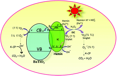 |
| | Scheme 1 The robust photocatalytic efficiency of the hemin anchored BaTiO3 photocatalyst is due to the synergetic effect that occurs among photosensitization, formation of reactive singlet oxygen and the redox reactions involving iron in the +2 and +3 oxidation states. | |
4.2. Formation of highly reactive singlet oxygen
The electronic configuration of molecular oxygen is (1sσg)2 (1sσu)2 (2sσg)2 (2sσu)2 (2pσg)2 (2pxπu)2 (2pyπu)2 (2pxπg)1 (2pyπg)1, in which the (1sσg)2 (1sσu)2 (2sσg)2 orbitals are non-bonding, the (2sσu)2 (2pσg)2 (2pxπu)2 (2pyπu)2 orbitals are bonding and the (2pxπg)1 (2pyπg)1 orbitals are antibonding. The antibonding orbitals, (2pxπg)1 (2pyπg)1, have two unpaired electrons of spin  each. The total spin S is equal to one and the spin multiplicity (2S + 1) is equal to triplet.36 Electron transfer to this triplet state can be represented in the following two ways: (i) the electron can get transferred from the LUMO of the hemin molecule directly to the triplet state of oxygen; (II) alternatively, the two step electron transfer process can be depicted as the first from the LUMO of the hemin molecule to the CB of BTO and in turn to the triplet oxygen state.38 These two electron transfer processes convert the multiplicity of oxygen from the triplet to the singlet state. The yield of this singlet oxygen is generally higher in the case of porphyrins.39 Thus, the formed singlet oxygen with a higher oxidant properties readily oxidises 4-CP and enhances the degradation rate (Scheme 1).
4.3. Effect of crystallite size
It is generally observed that the smaller the crystallite size, the higher will be the photocatalytic activity.1 Enhanced photocatalytic activity was observed in the case of HBTO with smaller crystallite size compared to BTO. The decrease in crystallite size leads to the reduction in the diffusion path length for the movement of the charge carriers from the site where they were photogenerated to the surface site where they possibly react. Reduction in this diffusion path length results in a reduced recombination rate of photogenerated carriers and hence results in higher photocatalytic efficiency. Further, reduction in crystallite size is beneficial in two ways: (i) surface area increases, thereby increasing the number of available surface active sites for efficient adsorption of the substrate molecules; (ii) the increase in the surface area also increases the photonic absorption cross-section, which results in higher photonic efficiency.
4.4. Influence of H2O2 on the photocatalytic activity
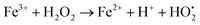
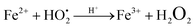
The photodegradation efficiency drastically increased with the addition of H2O2 to the reaction mixture containing HBTO (Fig. 10 & Table 3). H2O2 reacted with photogenerated electrons in the presence of HBTO under visible light irradiation. The enhancement in the degradation rate was due to the formation of hydroxyl radicals. The extent of the photogeneration of hydroxyl radicals in the system further increased due to the presence of superoxide radicals as shown in eqn (6) and (7).40 In addition, the Fe3+ ion in the hemin molecule can react with the H2O2 molecule in the photo-Fenton process.19 There is a remarkable enhancement in the rate of photocatalytic degradation due to the continuous cyclic process, in which the Fe3+ ion of hemin reacts with H2O2 to generate the Fe2+ ion and peroxo radical  as shown in eqn (8). The
  free radicals, in turn, can react with Fe2+ ions in the presence of H+ ions to regenerate Fe3+ ions and H2O2 as shown in eqn (9).19 An enriched concentration of hydroxyl radicals and various other reactive free radicals continuously take active part in the degradation reaction. The rate constant for the reaction with H2O2 increased drastically (almost 80 times). Further, the photonic efficiency also increased by almost a hundred times. A synergetic effect exists between the photosensitization process and the photo-Fenton process, which is responsible for the dramatic increase in the efficiency of the catalyst under visible light.
| | 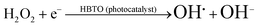 | (6) |
| |  | (7) |
| |  | (8) |
| |  | (9) |
The Fe3+ ion has a half-filled electronic configuration (EC) with singly occupied electrons in five 3d orbitals. The total orbital angular momentum L = 0, the total spin  and the spin multiplicity (2S + 1) is 6. Hence, the energy states/term symbols for the Fe3+ ion are 3 6S5/2 and 3 6S3/2. Similarly, for the Fe2+ ion L = 2,
  and (2S + 1) = 5 and the term symbols are 3 5D4, 3 5D3 and 3 5D0. Since the EC of Fe3+ ion is half-filled and that of Fe2+ ion is more than half-filled, the most stable energy state in both cases is the one with the higher J value.36 Hence, 3 6S5/2 for Fe3+ ion and 3 5D4 for Fe2+ ion are the most stable states; thus, during the cyclic photo-Fenton process the maximum probability of finding iron can be in these two energy states. Further, the crystal field stabilization energy (CFSE) is zero for d5 EC and has a very small value for d6. Therefore, Fe3+ state is more stable than Fe2+ state. The term symbols and the CFSE values confirm the stable state of iron as Fe3+. The iron ion tries to achieve this stable state by either trapping or detrapping the electrons.36 When the electron is trapped by the Fe3+ ion, the stability of the ion is lost and such a state is referred to as the shallow trapping center. Detrapping of this shallow trapped electron takes place more spontaneously to attain a stable half-filled electronic configuration, which occurs in a continuous cyclic process.
5. Trapping of free radicals (by TBA) and holes (EDTA)
Photocatalytic activity is influenced by both active free radicals and oxidative holes. In the present study, a set of experiments were performed in order to evaluate the exact role of free radicals and holes by using well-known scavengers like TBA and EDTA, respectively.41 The results showed that the extent of photodegradation of 4-CP was hardly inhibited by the addition of EDTA, while it was extensively suppressed by the addition of TBA (Fig. 10 & Table 3). This indicates that free radicals like OH˙ and O2˙− were the main active species that could oxidize the adsorbed 4-CP molecule rather than oxidative holes.
6. Study of reaction intermediates by the GC-MS technique
The formation of intermediates during the degradation process using the HBTO photocatalyst were identified by the GC-MS technique.42 The sample was withdrawn from the reaction mixture at time intervals of 30 min, and this aqueous sample was extracted into chloroform solvent. This sample showed two peaks with retention times of 9.973 and 11.189 min. The corresponding mass spectra recorded at the retention time 9.973 min showed a molecular ion peak corresponding to m/z of 4-CP at 127.9 and (m + 2) peak at 129.9 in the ratio of 3:1. The m/z peak at 11.189 in the spectra can be attributed to the formation of hydroquinone, due hydroxyl radical attack resulting in the elimination of the Cl group, followed by subsequent oxidation. The sample after 105 min of irradiation showed two peaks at retention times of 7.373 and 11.190 min in the GC spectra corresponding to benzoquinone and hydroquinone, respectively. The sample after 160 min did not show any major peaks, implying the complete degradation of 4-CP. The GC-MS results are provided in Table 4 and Fig. S2.†
Table 4 The values of retention time, m/z values and the major intermediates formed at given time intervals as analyzed by the GC-MS technique
| Retention time |
m/z values |
Intermediates |
Time interval |
| 9.973 |
129.9 |
4-Chlorophenol |
30 min |
| 11.189 |
110 |
Hydroquinone |
| 7.373 |
108 |
Benzoquinone |
105 min |
| 11.190 |
110 |
Hydroquinone |
7. Proposed degradation reaction mechanism of 4-CP
The degradation pathway is proposed based on the results obtained by the GC-MS analysis. The major identified intermediates are hydroquinone (HQ) and benzoquinone (BQ). The photodegradation of the 4-CP can be predicted to occur by the attack of hydroxyl radicals. Thus, the hydroxylation of 4-CP leads to the formation of the HQ intermediate. Further, HQ undergoes dehydrogenation to form BQ. Subsequently, BQ upon ring cleavage and successive oxidation, forms aliphatic carboxylic acids, which are finally degraded into small molecules like CO2 and H2O as proposed in Scheme 2.43
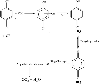 |
| | Scheme 2 Proposed photocatalytic degradation mechanism of 4-CP. | |
8. Photostability and reusability of the HBTO photocatalyst
To evaluate the photostability and reusability of the HBTO photocatalyst, four consecutive degradation experiments were performed under solar light irradiation. At the end of each experiment, the catalyst particles were centrifuged and separated from the solution. Then, the catalyst particles were thoroughly washed 5–6 times and dried before reuse. The efficiency of the catalyst decreased by almost 5% after each cycle (Fig. S3†). FTIR spectra of the HBTO photocatalyst were recorded at the end of each cycle and the spectra do not show any structural changes. Both the stretching modes of the hemin moiety and the carboxylate groups were present, further confirming the presence of characteristic peaks of the HBTO photocatalyst. Therefore, the HBTO is found to be photostable with good reusability.
9. Conclusion
The excellent visible light photocatalytic activity of the HBTO catalyst over the BTO catalyst is due to a number of cooperative functions and synergetic effects that can possibly occur within the hemin molecule and at the interface between hemin and BTO. This synergetic effect includes efficient photosensitization, formation of reactive singlet oxygen and the redox reactions involving iron in the +2 and +3 oxidation states. Trapping and detrapping of photogenerated electrons takes place between 3 6S5/2 and 3 5D4 energy states of the Fe3+ and Fe2+ ions. The CFSE and the term symbols imply that iron exists in the +3 oxidation state due to its half-filled EC. Enormously enhanced photocatalytic efficiency was observed in the presence of oxidizing agent (H2O2) due to the synergetic effects between photocatalysis, photosensitization and photo-Fenton process, which increased the extent of production of hydroxyl radicals in the system. The process of electron trapping either by oxygen triplet or by Fe3+ ion in the hemin molecule (in the presence of H2O2) reduced the recombination of photogenerated charge carriers. In the presence of hydroxyl radical scavenger, the rate of degradation decreased rapidly, implying the crucial role played by the hydroxyl radicals. The 4-CP degradation pathway was predicted by the qualitative identification of two major reaction intermediates like hydroquinone and benzoquinone by the GC-MS technique.
Conflicts of interest
There are no conflicts of interest to be declared.
Acknowledgements
The authors acknowledge University Grants Commission and Department of Science and Technology, Government of India for their financial supports.
References
- S. G. Kumar and L. G. Devi, J. Phys. Chem. A, 2011, 115, 13211–13241 CrossRef CAS PubMed.
- J. Cao, Y. Ji, C. Tian and Z. Yi, J. Alloys Compd., 2014, 615, 243–248 CrossRef CAS.
- G. M. Wang, Y. C. Ling and Y. Li, Nanoscale, 2012, 4, 6682–6691 RSC.
-
(a) P. Ren, H. Fan and X. Wang, Catal. Commun., 2012, 25, 32–35 CrossRef CAS;
(b) L. Ren, Y. Li, J. Hou, J. Bai, M. Mao, M. Zeng, X. Zhao and N. Li, Appl. Catal., B, 2016, 181, 625–634 CrossRef CAS;
(c) Y. Li, W. Xie, X. Hu, G. Shen, X. Zhou, Y. Xiang, X. Zhao and P. Fang, Langmuir, 2010, 26, 591–597 CrossRef CAS PubMed;
(d) Y. Li, X. Zhou, X. Hu, X. Zhao and P. Fang, J. Phys. Chem. C, 2009, 113, 16188–16192 CrossRef CAS;
(e) Y. Li, H. Zhang, X. Hu, X. Zhao and M. Han, J. Phys. Chem. C, 2008, 112, 14973–14979 CrossRef CAS.
- H. Zheng, J. Wang, S. E. Lofland, Z. Ma, L. Mohaddes-Ardabili, T. Zhao, L. Salamanca-Riba, S. R. Shinde, S. B. Ogale, F. Bai, D. Viehland, Y. Jia, D. G. Schlom, M. Wuttig, A. Roytburd and R. Ramesh, Science, 2004, 303, 661–663 CrossRef CAS PubMed.
- S. Afzal, W. A. Daoud and S. J. Langford, ACS Appl. Mater. Interfaces, 2013, 5, 4753–4759 CAS.
- Y. Cho, W. Choi, C. H. Lee, T. Hyeon and H. I. Lee, Environ. Sci. Technol., 2001, 35, 966–970 CrossRef CAS PubMed.
- C. Wang, J. Li, G. Mele, G. Yang, F. Zhang, L. Palmisano and G. Vasapollo, Appl. Catal., B, 2007, 76, 218–226 CrossRef CAS.
- Q. Maa, S. Ai, H. Yin, Q. Chen and T. Tang, Electrochim. Acta, 2010, 55, 6687–6694 CrossRef.
- Y. Zhang, Z. Xia, H. Liu, M. Yang, L. Lin and Q. Li, Sens. Actuators, B, 2013, 188, 496–501 CrossRef CAS.
- L. G. Devi and G. Krishnamurthy, J. Phys. Chem. A, 2011, 115, 460–469 CrossRef CAS PubMed.
- M. L. ArunaKumari and L. G. Devi, Environ. Sci.: Water Res. Technol., 2015, 1, 177–187 CAS.
- D. S. Tsoukleris, A. I. Kontos, P. Aloupogiannis and P. Falaras, Catal. Today, 2007, 124, 110–117 CrossRef CAS.
- K. Maeda, ACS Appl. Mater. Interfaces, 2014, 6, 2167–2173 CAS.
- Y. Zhu, K. Yan, Z. Xu and J. Zhangz, J. Electrochem. Soc., 2016, 163, B526–B532 CrossRef CAS.
- H. Huang, X. Gu, J. Zhou, K. Ji, H. Liu and Y. Feng, Catal. Commun., 2009, 11, 58–61 CrossRef CAS.
- L. G. Devi and P. M. Nithya, J. Environ. Chem. Eng. DOI:10.1016/j.jece.2017.04.038.
-
(a) J. Desilvetro, M. Graetzel, L. Kavan and J. Moser, J. Am. Chem. Soc., 1985, 107, 2988–2990 CrossRef;
(b) L. G. Devi and M. L. ArunaKumari, Appl. Surf. Sci., 2013, 276, 521–528 CrossRef CAS.
-
X. Wang, W. Guo, Y. Hu, J. Wu and H. Wei, Nanozymes: Next wave of artificial enzymes, Springer (Technology and engineering), 2016, pp. 1–109 Search PubMed.
- R. Kavitha and L. G. Devi, J. Environ. Chem. Eng., 2014, 2, 857–867 CrossRef CAS.
- G. Tian, K. Pan, H. Fu, L. Jing and W. Zhou, J. Hazard. Mater., 2009, 166, 939–944 CrossRef CAS PubMed.
- C. Wei, S. Kuo, Y. Hung, W. Huang, F. Adriyanto and Y. Wang, IEEE Electron Device Lett., 2011, 32, 90–92 CrossRef CAS.
- S. A. Nasser, Appl. Surf. Sci., 2000, 157, 14–22 CrossRef CAS.
- T. Ma, K. Inoue, H. Noma, K. Yao and E. Abe, J. Photochem. Photobiol., A, 2002, 152, 207–212 CrossRef CAS.
- S. Nayak, B. Sahoo, T. K. Chakia and D. Khastgir, RSC Adv., 2014, 4, 1212–1224 RSC.
- Y. Guo, L. Deng, J. Li, S. Guo, E. Wang and S. Dong, ACS Nano, 2011, 5, 1282–1290 CrossRef CAS PubMed.
- Z. X. Liang, H. Y. Song and S. J. Lia, J. Phys. Chem. C, 2011, 115, 2604–2610 CAS.
- L. G. Devi and R. Kavitha, Mater. Chem. Phys., 2014, 143, 1300–1308 CrossRef CAS.
- Y. Cong, J. L. Zhang, F. Chen and M. Anpo, J. Phys. Chem. C, 2007, 111, 6976–6982 CAS.
- J. L. Zhang, Y. Hu, M. Matsuoka, H. Yamashita, M. Minagawa, H. Hidaka and M. Anpo, J. Phys. Chem. B, 2001, 105, 8395–8398 CrossRef CAS.
- M. Zhang, J. Yu, J. Chu, Q. Chen and W. Chen, J. Mater. Process. Technol., 2003, 137, 78–81 CrossRef CAS.
- S. G. Kruglik, P. A. Apanasevich, V. S. Chirvony, V. V. Kvach and V. A. Orlovich, J. Phys. Chem., 1995, 99, 2978–2995 CrossRef CAS.
- C. Wang, J. Li, G. Mele, G. M. Yang, F. X. Zhang, L. Palmisano and G. Vasapollo, Appl. Catal., B, 2007, 76, 218–226 CrossRef CAS.
- L. G. Devi, P. M. Nithya, C. Abraham and R. Kavitha, Mater. Today Commun., 2017, 10, 1–13 CrossRef CAS.
- W. J. Suna, J. Li, G. P. Yao, F. X. Zhang and J. L. Wang, Appl. Surf. Sci., 2011, 258, 940–945 CrossRef.
- S. Ligenza, Phys. Status Solidi B, 1976, 75, 315–326 CrossRef CAS.
- M. Y. Duan, J. Li, M. Li, Z. Q. Zhang and C. Wang, Appl. Surf. Sci., 2012, 258, 5499–5504 CrossRef CAS.
- N. Murakami, A. Ono, M. Nakamura, T. Tsubota and T. Ohno, Appl. Catal., B, 2010, 97, 115–119 CrossRef CAS.
- D. Frackowiak, A. Planner, A. Waszkowiak, A. Boguta, R. M. Ion and K. Wiktorowicz, J. Photochem. Photobiol., A, 2001, 141, 101–108 CrossRef CAS.
-
(a) J. Kim, C. W. Lee and W. Choi, Environ. Sci. Technol., 2010, 44, 6849–6854 CrossRef CAS PubMed;
(b) J. Yu, J. C. Yu, M. K. P. Leung, W. Ho, B. Cheng, X. Zhao and J. Zhao, J. Catal., 2003, 217, 69–78 CAS.
- H. Lee, S. H. Park, Y. K. Park, S. J. Kim, S. G. Seo, S. J. Ki and S. C. Jung, Chem. Eng. J., 2015, 278, 259–264 CrossRef CAS.
- L. G. Devi, S. G. Kumar, K. Mohan Reddy and C. Munikrishnappa, J. Hazard. Mater., 2009, 164, 459–467 CrossRef PubMed.
- S. J. Ki, K. Jeon, Y. Park, S. Jeong, H. Lee and S. Jung, Catal. Today, 2017, 293–294, 15–22 CrossRef CAS.
Footnote |
| † Electronic supplementary information (ESI) available. See DOI: 10.1039/c7qi00590c |
|
| This journal is © the Partner Organisations 2018 |

 * and
P. M.
Nithya
* and
P. M.
Nithya


 , non-centrosymmetric Ti3+ state associated with oxygen vacancy (Ti3+-νo) and intrinsic structural defects, which are responsible for the PL emission at 470 nm. Therefore, the peak at 470 nm can account for both recombination reactions occurring due to the presence of the abovementioned defects in BTO and also due to the presence of hemin in HBTO. This peak intensity is considerably decreased for HBTO, since the hemin moiety provides free channels of the type O


 each. The total spin S is equal to one and the spin multiplicity (2S + 1) is equal to triplet.36 Electron transfer to this triplet state can be represented in the following two ways: (i) the electron can get transferred from the LUMO of the hemin molecule directly to the triplet state of oxygen; (II) alternatively, the two step electron transfer process can be depicted as the first from the LUMO of the hemin molecule to the CB of BTO and in turn to the triplet oxygen state.38 These two electron transfer processes convert the multiplicity of oxygen from the triplet to the singlet state. The yield of this singlet oxygen is generally higher in the case of porphyrins.39 Thus, the formed singlet oxygen with a higher oxidant properties readily oxidises 4-CP and enhances the degradation rate (Scheme 1).
 as shown in eqn (8). The
  free radicals, in turn, can react with Fe2+ ions in the presence of H+ ions to regenerate Fe3+ ions and H2O2 as shown in eqn (9).19 An enriched concentration of hydroxyl radicals and various other reactive free radicals continuously take active part in the degradation reaction. The rate constant for the reaction with H2O2 increased drastically (almost 80 times). Further, the photonic efficiency also increased by almost a hundred times. A synergetic effect exists between the photosensitization process and the photo-Fenton process, which is responsible for the dramatic increase in the efficiency of the catalyst under visible light.


 and the spin multiplicity (2S + 1) is 6. Hence, the energy states/term symbols for the Fe3+ ion are 3 6S5/2 and 3 6S3/2. Similarly, for the Fe2+ ion L = 2,
  and (2S + 1) = 5 and the term symbols are 3 5D4, 3 5D3 and 3 5D0. Since the EC of Fe3+ ion is half-filled and that of Fe2+ ion is more than half-filled, the most stable energy state in both cases is the one with the higher J value.36 Hence, 3 6S5/2 for Fe3+ ion and 3 5D4 for Fe2+ ion are the most stable states; thus, during the cyclic photo-Fenton process the maximum probability of finding iron can be in these two energy states. Further, the crystal field stabilization energy (CFSE) is zero for d5 EC and has a very small value for d6. Therefore, Fe3+ state is more stable than Fe2+ state. The term symbols and the CFSE values confirm the stable state of iron as Fe3+. The iron ion tries to achieve this stable state by either trapping or detrapping the electrons.36 When the electron is trapped by the Fe3+ ion, the stability of the ion is lost and such a state is referred to as the shallow trapping center. Detrapping of this shallow trapped electron takes place more spontaneously to attain a stable half-filled electronic configuration, which occurs in a continuous cyclic process.