 Open Access Article
Creative Commons Attribution 3.0 Unported Licence
3D printed scaffolds with gradient porosity based on a cellulose nanocrystal hydrogel†
Sahar
Sultan
and
Aji P.
Mathew
 *
*
Division of Materials and Environmental Chemistry, Stockholm University, SE-10691 Stockholm, Sweden. E-mail: aji.mathew@mmk.su.se; Tel: +46 8161256
First published on 24th January 2018
Abstract
3-Dimensional (3D) printing provides a unique methodology for the customization of biomedical scaffolds with respect to size, shape, pore structure and pore orientation useful for tissue repair and regeneration. 3D printing was used to fabricate fully bio-based porous scaffolds of a double crosslinked interpenetrating polymer network (IPN) from a hydrogel ink of sodium alginate and gelatin (SA/G) reinforced with cellulose nanocrystals (CNCs). CNCs provided favorable rheological properties required for 3D printing. The 3D printed scaffolds were crosslinked sequentially via covalent and ionic reactions resulting in dimensionally stable hydrogel scaffolds with pore sizes of 80–2125 μm and nanoscaled pore wall roughness (visible from scanning electron microscopy) favorable for cell interaction. The 2D wide angle X-ray scattering studies showed that the nanocrystals orient preferably in the printing direction; the degree of orientation varied between 61–76%. The 3D printing pathways were optimised successfully to achieve 3-dimensional scaffolds (Z axis up to 20 mm) with uniform as well as gradient pore structures. This study demonstrates the potential of 3D printing in developing bio-based scaffolds with controlled pore sizes, gradient pore structures and alignment of nanocrystals for optimal tissue regeneration.
Introduction
There is a growing interest towards the use of biopolymers in biomedical scaffolds and implants. Among them, biopolymers such as chitosan, gelatin and alginate are of special interest as they are natural components of living structures and they possess biological and chemical similarities to natural tissues.1–3 However, nanoreinforcements are widely used to enhance the mechanical properties of biopolymer-based scaffolds irrespective of their use as load bearing implants or as non-load bearing scaffolds tuned for cell adhesion, growth and tissue regeneration.4 Nanopolysaccharides have an added advantage in this context due to their bio-based origin, cytocompatibility and excellent mechanical properties. We have reported in the recent years scaffolds, implants and wound dressing materials based on nanocellulose and nanochitin as reinforcements in biopolymers prepared via casting, electrospinning or freeze-drying processes.5–9 These studies demonstrated nanostructured and cytocompatible scaffolds with high porosity, nanoscaled pore wall roughness, pore interconnectivity and wet mechanical properties suitable for biomedical applications. However, an accurate control of the pore sizes was not achieved through these processing techniques. Furthermore, the literature shows that there is no definite pore size range that can be considered as a benchmark for scaffolds, e.g. for cartilage tissue engineering, some studies showed higher bioactivity with smaller pores while others showed better cartilage regeneration with larger pores.10 Macropores facilitate tissue ingrowth, nutrient supply and waste removal while micropores facilitate cell attachment and better mechanical properties.11,12 One way to deal with the wide variations in pore sizes in the scaffolds is the introduction of gradient or hierarchical porosity, which is also observed in tissues such as skin, cartilage and bone. Gradient porosity is also known to promote specific cell migration during tissue engineering, which is a requirement, e.g., for the treatment of articular cartilage defects in osteochondral tissue engineering.13,143D printing technology provides a unique opportunity to develop 3D constructs with uniform or gradient porosity required for tissue regeneration using bio-based nanocomposites. Charles Hull, with a B.S. in engineering physics from the University of Colorado, introduced in the 1980s the concept of 3D printing,15 also known as additive manufacturing, rapid prototyping, and solid-free form technology. The revolution that 3D printing brings in medical applications is customization.
Here we present a 3D printable cellulose nanocrystal (CNC) based biocompatible nanocomposite hydrogel ink with alginate and gelatin as the matrix phase. Alginate is a popular choice for the polymer/matrix phase in 3D printing due to its bio-based origin, fast gelation by the addition of divalent cations such as Ca2+ and relatively low cost.2 However, alginate has low cell adhesion and cell proliferation capability and therefore it is often blended with other biopolymers such as gelatin and successfully used in 3D printing. The study by Chung et al.16 showed that the alginate and gelatin blend provides a potential means to print 3D constructs that may find myoregenerative applications. In another study, an alginate and gelatin hydrogel has been 3D printed to fabricate living heterogeneous aortic valve conduits,17 a promising strategy for tissue engineered living valve replacements.
The majority of the reports on 3D printing using nanocellulose focus on cellulose nanofibrils where the porous structures or controlled directionality of printing is used to achieve functional properties.18–23 Limited reports are available on 3D printing using CNCs.12,24,25 CNCs are expected to have an advantage in developing inks with higher solid content for 3D printing due to their lower aspect ratios compared to CNFs, and ease of changing the surface chemistry using different synthesis routes without compromising on the ability to support cell growth.26–28 Furthermore, CNCs are expected to provide favorable structural orientation and rheological and mechanical properties during the printing process.29–31 CNCs containing inks usually exhibit shear thinning behavior even without the addition of any rheology modifiers, where CNCs are oriented preferably in the printing direction.12,24
CNCs with carboxyl functional groups (charge density 0.5 mmol g−1) useful for crosslinking14 and with proven cytocompatibility (cell growth after 15 days of incubation)14,32 were used in the current study for the fabrication of biomedical hydrogel scaffolds. The aim of this study was to 3D print CNC based hydrogel scaffolds with uniform and/or gradient porosity. We have explored two different types of nozzle movements to obtain the same structure and optimized the 3D printing process. The crosslinking mechanisms, morphology, pore structure and CNC alignment during printing were studied.
Materials and methods
The cellulose extracted from unbarked Norway spruce wood chips (Picea abies) using the bioethanol processing plant at SEKAB (Örnsköldsvik, Sweden) and supplied as 17 wt% cellulose suspensions was used as the raw material for the processing of cellulose nanocrystals.Sodium alginate (alginic acid sodium salt from brown algae, Mw = 120![[thin space (1/6-em)]](https://www.rsc.org/images/entities/char_2009.gif) 000–190
000–190![[thin space (1/6-em)]](https://www.rsc.org/images/entities/char_2009.gif) 000 g mol−1) and gelatin (Bloom 225, Type B, Mw = 40
000 g mol−1) and gelatin (Bloom 225, Type B, Mw = 40![[thin space (1/6-em)]](https://www.rsc.org/images/entities/char_2009.gif) 000–50
000–50![[thin space (1/6-em)]](https://www.rsc.org/images/entities/char_2009.gif) 000 g mol−1) used as the matrix were purchased from Sigma-Aldrich (Germany).
000 g mol−1) used as the matrix were purchased from Sigma-Aldrich (Germany).
Calcium chloride (CaCl2, Mw = 110.98 g mol−1) and glutaraldehyde (50 wt% in H2O, Mw = 100.12 g mol−1) used as crosslinkers were purchased from Sigma-Aldrich (Germany).
Isolation of CNCs
Cellulose nanocrystals with carboxyl functional groups on the surface were isolated from a cellulose suspension according to the procedure previously reported by our group.32 1.5 wt% Suspensions from the purified cellulose were prepared and sonicated using ultrasonication, and then passed through a APV 2000 high-pressure homogenizer (Denmark) at a pressure of 500 bars. Afterwards, the suspension with a batch size of 2 L was passed through the homogenizer 10 times until a thick gel of cellulose nanocrystals (CNCs) was obtained. This process takes about 40 minutes per batch. The CNCs formed a thick gel at 1.5 wt%, which showed flow birefringence under cross-polarized light (Fig. 1a) and a nanoscaled morphology with diameters below 10 nm was confirmed by AFM imaging (Fig. 1b, c and d).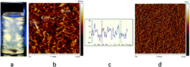 | ||
| Fig. 1 (a) 1.5 wt% CNC flow birefringence under cross-polarized light. (b, c, d) AFM images of CNCs confirming diameters below 10 nm. | ||
3D printing
The 3D printer used was a Discov3ry Complete paste printing system from Structur3D Printing (http://www.structur3d.io). The 3D printer itself is an Ultimaker 2+ (http://www.ultimaker.com), and the integrated Discov3ry paste extruder enables this printer to print paste materials. A CAD model in an stl file was converted to a gcode file to be read by the printer.Prior to printing, hydrogel ink filled syringes were gently centrifuged to remove air bubbles and then loaded into the cartridge. For all prints, a nozzle diameter of 410 μm, a flow rate of 70–120% and a printing speed of 10–80 mm s−1 were used.
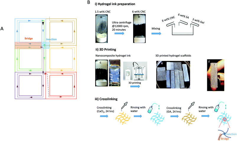
The schematic representation of nozzle movement-A (NM-A) used to acquire 3D printed scaffolds is shown in Fig. 2A and the printed scaffolds are shown in Table 1. From Fig. 2A, it can be noted that each pore of the scaffold is composed of similar blocks (each block is shown with one color) connected to each other. The black arrow indicates the start of the printing in the forward direction where all the four sides of each block are printed. Once the nozzle reaches the end of the forward direction printing, it jumps (indicated by a black dotted line) to start printing in the backward direction where only three sides of each block are printed (the fourth side being already printed during the forward direction). Each block shares its bridge and junction positions with its neighboring blocks. In this way, the walls of each pore are printed twice (the video of NM-A is provided in the ESI†).
(i) A thick aqueous 1.5 wt% CNC gel obtained through homogenization was concentrated to 6 wt% by centrifugation using a Fiberlite™ F12-6 × 500 LEX Fixed Angle Rotor with Auto-Lock at 12![[thin space (1/6-em)]](https://www.rsc.org/images/entities/char_2009.gif) 000 rpm. The matrix phases were prepared at 50 °C in the form of 3 wt% gelatin (Gel) solution and 6 wt% sodium alginate (SA) solution in distilled water. 6 wt% CNC and the matrix phases were mixed to reach a composition of CNC/SA/Gel: 70/20/10 (wt%) under dry conditions.
000 rpm. The matrix phases were prepared at 50 °C in the form of 3 wt% gelatin (Gel) solution and 6 wt% sodium alginate (SA) solution in distilled water. 6 wt% CNC and the matrix phases were mixed to reach a composition of CNC/SA/Gel: 70/20/10 (wt%) under dry conditions.
(ii) Seven different scaffolds were 3D printed: one was the reference with no pores, four uniformly porous scaffolds were prepared with each one having 0.5 mm, 1 mm, 1.5 mm and 2 mm pore size, and two gradient porous scaffolds were prepared with pore sizes of 0.5–2 mm and 1 mm–2 mm.
(iii) The 3D printed hydrogel scaffolds were crosslinked with 3 wt% CaCl2 solution for 24 hours, washed properly with distilled water and crosslinked again with 3 wt% glutaraldehyde (GA) solution for another 24 hours.
After double crosslinking, the 3D printed scaffolds were washed properly and stored in distilled water until further characterization.
Characterization
Structure of 3D printed hydrogel scaffolds
 | (1) |
The pore sizes of the 3D printed hydrogel scaffolds were measured before and after freeze-drying. ImageJ was used to measure the pore sizes from optical microscopy (OM) images that were collected using an optical microscope (Olympus stereomicroscope Model SZX12, Japan).
Orientation effects during 3D printing
 | (2) |
Mechanical properties
To evaluate the mechanical properties of the nanocomposite hydrogel scaffolds, tensile tests were performed using a 5943 1 kN single column electromechanical testing system equipped with a 100 N load cell. The tests were performed on wet samples (double crosslinked and stored in water) using a BioPuls Bath system at a rate of 2 mm min−1.Results and discussion
Flow behaviour of nanocomposite hydrogel ink
Fig. 3 shows the rheological properties of the hydrogel ink as a function of shear rate and shear stress. A strong non-Newtonian shear thinning behavior of the nanocomposite hydrogel ink is clearly observed in Fig. 3a. The apparent viscosity of 6.92 × 10⁴ Pa s at a low shear rate (0.001 s−1) drops by four orders of magnitude to a value of 8.80 Pa s at a shear rate of 50 s−1 (≈50 s−1 being a typical shear rate experienced during 3D printing33). When the viscosity of the hydrogel ink drops at higher shear rates during extrusion, the ink behaves more like a liquid rather than a solid. However, as soon as the shear rate drops, the viscosity of the ink increases immediately, making the print more solid-like. This shear thinning property is an important factor in keeping the shape of the print intact after extrusion.21 As compared to the nanocomposite hydrogel ink, the matrix only had a viscosity of 2.16 Pa s at a low shear rate (0.01 s−1), which is lower by four orders of magnitude. The matrix showed no shear thinning behavior which suggests that the matrix alone is not printable.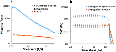 | ||
| Fig. 3 Log–log plots of nanocomposite hydrogel ink (a) viscosity vs. shear rate and (b) G′ and G′′ vs. shear stress. | ||
The linear viscoelastic (LVE) region has been defined by a strain sweep experiment (Fig. S1, ESI†). The ink was further characterized using a frequency sweep (Fig. S2, ESI†) at a strain below the critical strain (γc = 11.1%). Below the critical strain, G′ is nearly independent of the frequency and is always greater than G′′, as expected from a solid-like material.
Fig. 3b shows that the hydrogel ink exhibits a viscoelastic solid behavior, as the storage modulus G′ (1.98 × 10⁴ Pa) is an order of magnitude greater than the loss modulus G′′ (3.02 × 10³ Pa) at low shear stress, with a well-defined dynamic yield stress value (G′ = G′′) of 3.80 × 10³ Pa. This solid-like behavior of the hydrogel ink is highly desirable for 3D printing of structures for subsequent ex situ crosslinking, as it crucial to render dimensional stability and shape fidelity until the completion of the print.
Crosslinking mechanism
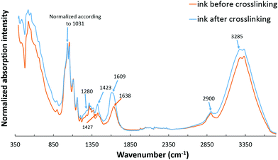
The presence of functional groups of all the components involved in the hydrogel ink was confirmed with the FTIR spectra of the nanocomposite hydrogel ink recorded before and after double crosslinking (Fig. 4). The FTIR spectrum for a 6 wt% CNC gel is given in the ESI (Fig. S3†). The spectra given in Fig. 4 show typical peaks corresponding to sodium alginate, gelatin and CNC. The first absorption band at 3400–3000 cm−1 is assigned to O–H stretching vibrations; the band at 2900 cm−1 is due to symmetric and asymmetric C–H stretching vibrations of aliphatic chains for sodium alginate. The second absorption band at 1609 cm−1 is due to asymmetric and symmetric stretching vibrations of the carboxylate salt groups of alginate.34,35 The absorption bands of the polysaccharide structure of sodium alginate appear at 1314, 1159 and 1031 cm−1 corresponding to C–O, C–C, and C–O–C stretching.9,36 The FTIR spectrum of gelatin found in our spectrum focuses mainly on peptide bands named Amide A and Amide I–III.34 Amide A band is due to the intense infrared absorption of N–H stretching vibrations and is observed at about 3285 cm−1. Amide I band is observed at 1638 cm−1 which is due to the C![[double bond, length as m-dash]](https://www.rsc.org/images/entities/char_e001.gif) O and C–N stretching vibrations, and Amide III band is at 1280 cm−1 which is attributed to C–N stretching vibrations.9 It should be noted that Amide II band due to N–H bending vibrations, which usually appears at 1543 cm−1, is absent in the nanocomposite hydrogel ink suggesting the involvement of this group in the primary crosslinking reaction between sodium alginate and gelatin.36 The presence of CNC is observed by the absorption bands between 3400 and 3000 cm−1 assigned to O–H stretching; the band at 2900 cm−1 is due to C–H stretching vibrations of aliphatic chains, and the band around 1640 cm−1 is attributed to the deformation vibrations of bound water molecules. The characteristic absorption bands between 800–1400 cm−1 correspond to the C–H, O–H, C–O and C–O–C vibrations on the glucosidic ring.9,35
O and C–N stretching vibrations, and Amide III band is at 1280 cm−1 which is attributed to C–N stretching vibrations.9 It should be noted that Amide II band due to N–H bending vibrations, which usually appears at 1543 cm−1, is absent in the nanocomposite hydrogel ink suggesting the involvement of this group in the primary crosslinking reaction between sodium alginate and gelatin.36 The presence of CNC is observed by the absorption bands between 3400 and 3000 cm−1 assigned to O–H stretching; the band at 2900 cm−1 is due to C–H stretching vibrations of aliphatic chains, and the band around 1640 cm−1 is attributed to the deformation vibrations of bound water molecules. The characteristic absorption bands between 800–1400 cm−1 correspond to the C–H, O–H, C–O and C–O–C vibrations on the glucosidic ring.9,35
For the uncrosslinked nanocomposite hydrogel ink, a strong absorption band is present at 1638 cm−1 that is assigned to the asymmetric stretching vibrations of COO−. At the same time, the absorption band at 1427 cm−1 assigned to the symmetric stretching vibrations of COO− is also present. It may therefore be concluded that a certain degree of primary interaction between sodium alginate (carboxyl groups) and gelatin (amino groups) due to the formation of intermolecular hydrogen bonds has already taken place, even before the double crosslinking step.37
In the first step of crosslinking, calcium chloride solution was added to 3D printed scaffolds. The divalent cations, Ca2+, crosslink SA through ionic interaction between Ca2+ and carboxyl groups. This can be inferred from the band at 1423 cm−1 due to the intermolecular interactions between SA and carboxyl groups on CNC to form a crosslinked network. In addition, intense bands at 1609 cm−1 and 3400–3000 cm−1 suggest an increase of hydrogen bonds between SA and CNC.9 The second step of the crosslinking mechanism of gelatin with glutaraldehyde can be explained through the reaction of the aldehyde functional groups with free non-protonated amino groups (–NH2) through a nucleophilic addition-type reaction.38 This can be confirmed by the disappearance of the band at 1638 cm−1 after crosslinking suggesting that the NH2 of gelatin is used up during the reaction with glutaraldehyde. Also, glutaraldehyde is a dialdehyde that reacts with an amine group in the gelatin to form a Schiff base, which is confirmed by the band due to C![[double bond, length as m-dash]](https://www.rsc.org/images/entities/char_e001.gif) N stretching vibration that is slightly shifted lower to 1609 cm−1 but increased in intensity.39 The detailed mechanism of both crosslinking steps has been studied thoroughly.9,38
N stretching vibration that is slightly shifted lower to 1609 cm−1 but increased in intensity.39 The detailed mechanism of both crosslinking steps has been studied thoroughly.9,38
Porosity and pore size
The pore structure of the 3D printed nanocomposite hydrogel scaffolds was evaluated before and after freeze-drying and is presented in Table 2. In general, it was noted that the pore structures measured are different from the theoretical pore sizes in the input files used for printing. The highest porosity was exhibited by the scaffold with 2 mm pore size and the porosity decreases with decreasing pore size, irrespective of the water content (hydrogel or freeze-dried). This suggests that as the pore size decreases, the pore wall content and hence the density increase. The porosity was the lowest for 0.5 mm pore size scaffolds as expected. The gradient porosity scaffolds also show the same trend; scaffolds that include 0.5 mm pore size have lower porosity (20% lower in the wet state and 8% lower in the FD state). Also, in all cases, the porosity in the dry state was higher than that in the wet state as expected, due to reduced swelling in the pore walls, once the water is removed.The pore sizes under wet and dry conditions were measured and generally, the pore size was larger in the dry state. For 0.5 mm pore size scaffolds, the pores were not visible in the wet state but after freeze-drying, small pores of sizes between 195–429 μm were visible. The 3D printing process has therefore resulted in scaffolds with pore sizes in the range of 80–2080 μm in the wet state and 195–2382 μm in the freeze-dried state.
It has been reported that in vitro cell interactions of different types of cells (chondrocytes, osteoblasts, and fibroblasts) depend on the pore size.40 For effective cell growth and tissue regeneration, a pore size range of 380–405 μm is favorable for chondrocytes and osteoblasts while pores in the range of 290–310 μm promote fibroblast growth and bone formation. There are also some studies showing that the pore sizes between 250–500 μm are beneficial for chondrocyte proliferation and extra cellular matrix (ECM) secretion.41 The pore structures obtained in the current 3D printed hydrogel scaffolds for 0.5 mm and 1 mm pore size were close to the ones required for cell growth and indicates their potential use in tissue regeneration.
Furthermore, the significance of multilayered scaffolds that replicate the graded mechanical properties of natural tissues involving density gradients42 and/or porous layers with varying porosity and pore size43,44 is well documented. Our gradient scaffolds have pore sizes in the range of 80–2080 μm with a controlled gradation in pore size and density along the print axis and can potentially mimic natural tissues.
The tensile data for 3D printed nanocomposite hydrogel scaffolds when measured under wet conditions showed a modulus of 1.54 MPa, tensile strength of 21.11 kPa and strain at break of 1.66% (average values) for 0.5 mm pore size (Fig. S4, ESI†). Though the mechanical property values were significantly lower than those for natural tissues, e.g. natural cartilage (tensile modulus of 5–25 MPa, tensile strength of 7–15 MPa and elongation to failure of 20%)54 or bone (Young's modulus of 15 GPa, tensile strength of 160 MPa and strain to failure of 2%),55 the pore size in the range of 400 microns is considered to be favorable for chondrocytes. In addition, these scaffolds can act as an excellent substrate for cell growth under in vivo conditions. The mechanical properties for 3D printed hydrogel scaffolds are close to those required for soft scaffolds (∼6 kPa) that facilitate chrondogenesis or stiffer scaffolds for bone regeneration (∼16 kPa) with high cytoskeleton tension.56 Therefore, once the pore structure and pore orientation in multiple layers are controlled via 3D printing, these scaffolds can be used in customized bone or cartilage regeneration.
Scanning electron microscopy
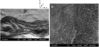
Fig. 5 shows the SEM images of the cross-section and top view of the surface of the freeze-dried 3D printed hydrogel scaffold of 1 mm pore size. Fig. 5a shows the cross section of the scaffold where the bridge and junction positions can be clearly identified. The layered morphology and a strong printing directionality in the bridge region (Fig. 5a, shown with arrows) can be seen clearly from the cross-section SEM image. Fig. 5b shows the SEM image for the top surface of the scaffold where a CNC percolating network within the matrix phase is clearly visible, but with random orientation. SEM images indicate that 3D printing results in nanocrystals oriented in the printing direction (XZ plane) and random orientation in the other directions (YZ and XY planes). Furthermore, Fig. 5b shows the nanoscaled roughness of the scaffold walls, which is considered to be beneficial for cell attachment and proliferation under in vivo conditions by improving the diffusion rates to and from the scaffold.8 In addition, the orientation of nanocrystals is well known to have a significant positive impact on guiding the cell growth during tissue regeneration.45Orientation effects in hydrogel scaffolds during 3D printing
![[thin space (1/6-em)]](https://www.rsc.org/images/entities/char_2009.gif) :
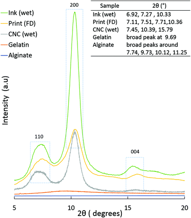
:![[thin space (1/6-em)]](https://www.rsc.org/images/entities/char_2009.gif) 70). In the case of Print (FD), a small shoulder, around 9.56°, is visible, (probably from the gelatin) but the cellulose peak dominates. This indicates that CNC has the major contribution to the scattering observed in the PXRD patterns.
70). In the case of Print (FD), a small shoulder, around 9.56°, is visible, (probably from the gelatin) but the cellulose peak dominates. This indicates that CNC has the major contribution to the scattering observed in the PXRD patterns.
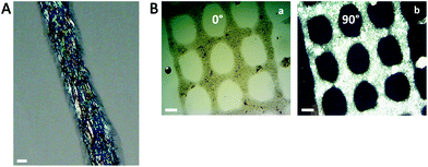
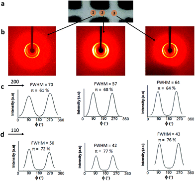
Fig. 8b shows that irrespective of the position, two rings are visible in the 2D-WAXS images, corresponding to two cellulose planes, 110 and 200 (2θ = 7.5° and 10.5°, respectively, based on the radial integration of the 2D-WAXS images). This confirms that cellulose is mainly contributing to the directionality. For all the three positions, azimuthal intensity distribution and degree of orientation were calculated for both the planes, 200 (Fig. 8c) and 110 (Fig. 8d). For plane 110, the degree of orientation is higher compared to that of its corresponding 200 plane. One reason could be that plane 110 is less populated but still oriented in a similar way as plane 200. The data show that the degree of orientation for CNCs varies with the point of measurement, it being highest in the middle, the bridge, i.e. position 2. The degree of orientation for the 3D printed hydrogel scaffolds decreases when measured at any angle other than 90°, e.g. 50° or 130° (Fig. S5, ESI†), which shows the strong directionality of CNCs along a specific direction, i.e. the printing direction. These results confirm the possibility of using 3D printing to build scaffolds and implants where directionality and orientation in nanoscale can be combined with gradient and hierarchical structures in micro- and macroscale required to replicate natural tissues such as bone or cartilage for optimal performance under in vivo conditions.53
3D Printing process optimization for printing 3D scaffolds
Siqueira et al.24 reported CNC composite hydrogels with a photocurable matrix with 10 or 20 wt% CNC and printed nanocomposite structures. The limitations were the use of organic solvents or surface modifications required for dispersing CNCs in the matrix phase. Palaganas et al.25 also recently reported a CNC composite using a photocurable matrix processed via stereolithography having CNC content as low as 1.2 wt%. Li et al.12 used polyamide–epichlorohydrin as a wet strength additive crosslinker to print and stabilise CNC based 3D printed structures (thermal curing) which were further freeze dried to form CNC aerogels with dual porosity.We have successfully developed and optimised a water based CNC hydrogel ink to 3D print biomedical scaffolds with accurate gradient pore structures. Ex situ crosslinking was performed under room conditions, which is time efficient though more challenging to print.
It may be noted that for all the 3D printing performed in this study, only one nozzle diameter, viz. 410 μm, was used. When a smaller nozzle diameter was used, the ink underwent phase separation due to pressure difference between the nozzle head (high pressure) and the transferring tube (low pressure). When a nozzle of a larger diameter was used, the resolution of the prints was adversely affected. Therefore, to control the ink flow through the nozzle, it was necessary to adjust the flow rate and printing speed. For smaller pore size scaffolds, low flow rate combined with high printing speed was used. Another smart way is the optimization of the nozzle movement in such a way that it will reduce the number of walls to be printed around the porous structures.
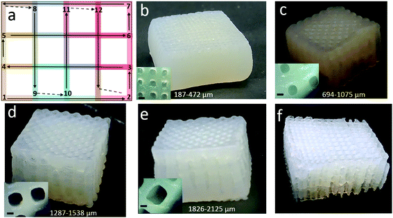
To build a 3D structure with higher Z-axis is a challenge when the hydrogel ink is post-cured after the complete print is done, i.e. ex situ crosslinking. This issue is usually reduced when the ink is photocured or UV-cured after each layer during printing, i.e. in situ crosslinking,24,25 even though the processing time increases significantly. NM-A was printing in such a manner that the walls of each pore were printed twice (Fig. 2) and the building layers in the Z-axis were not optimal as after a few layers the resolution was lost. Therefore, a new nozzle movement, nozzle movement-B (NM-B) (Fig. 9a), was attempted to prepare 3D constructs. Here too, each pore of the scaffold is composed of similar blocks (each block is shown with one color) connected to each other. In this case, the nozzle moves in a straight pattern. The movement starts at one side and goes to another. The printing pattern is alternating 90° angle lines (that form squares). In this way, the walls of each pore are printed once, and a higher Z-axis was successfully achieved with good printing resolution (the video of NM-B is provided in the ESI†). With the NM-B mode, 3D printed hydrogel scaffolds were successfully extended to a higher z-axis, as high as 20 mm. Four scaffolds with a uniform pore size of 0.5 mm, 1 mm, 1.5 mm and 2 mm were printed, and one gradient porous scaffold was printed with pore sizes of 1 mm–1.5 mm–2 mm, as shown in Fig. 9b, c, d, e and f respectively. It can also be noticed that the shape of the pore was well retained after printing and crosslinking confirming that for a successful 3D printing, a good input file is equally important.
The pore size distribution of these 3D printed hydrogel scaffolds was in the range of 187–2125 μm. These 3D scaffolds provide unique opportunities for tissue regeneration owing to the control of the pore structure, gradation in pore size, density and mechanical properties, nanoscaled pore wall roughness and oriented nanoscaled entities on pore walls that provide directed cell growth.
Conclusions
We have successfully developed water based cellulose nanocrystal hydrogel scaffolds via 3D printing with a control of the pore structure and report for the first time biomedical CNC scaffolds with gradient porosity within one 3D printed structure. In addition to hydrogel ink composition and its rheological properties, the print resolution and pore size control was driven by flow rate, print speed as well as the nozzle movement during printing. The pore sizes developed in this study varied between 80–2125 μm under wet conditions and these pore sizes can be distributed in the scaffold in a controlled manner which in turn provides gradation in density and mechanical properties in a preferred direction. CNC based hydrogel inks have an advantage over CNF based ones due to the ease of orientation under shear forces. Furthermore, the orientation of the nanostructures and nanoscaled pore wall roughness in 3D printed hydrogel scaffolds were considered to be suitable for cell interactions and guided cell growth during tissue regeneration. We believe that 3D printing can be used to tailor the pore directionality in different layers of the scaffold and will be reported in our future work. 3D printing of bio-based/water-based inks is expected to provide unpreceded flexibility to the development of medical implants and scaffolds with customized size, shape, structure and performance.Conflicts of interest
There are no conflicts to declare.Acknowledgements
The authors acknowledge the following: Knut och Alice Wallenberg Foundation, Wallenberg Wood Science Center for the financial support; Vincent Lundtröm from Studio3D Stockholm for designing 3D models; Lars Eriksson, Associate Professor at Stockholm University, for 2D-WAXS data collection and analysis; and Instron Testing Center, Norwood, MA, for tensile testing of hydrogel scaffolds in the wet state.References
- M. Sarem, F. Moztarzadeh and M. Mozafari, Carbohydr. Polym., 2013, 93, 635–643 CrossRef CAS PubMed
.
- K. Y. Lee and D. J. Mooney, Prog. Polym. Sci., 2012, 37, 106–126 CrossRef CAS PubMed
.
- I. Kim, S. Seo, H. Moon, M. Yoo, I. Park, B. Kim and C. Cho, Biotechnol. Adv., 2008, 26, 1–21 CrossRef CAS PubMed
.
- J. Corona-Gomez, X. Chen and Q. Yang, J. Funct. Biomater., 2016, 7, 18–29 CrossRef PubMed
.
- A. P. Mathew, K. Oksman, D. Pierron and M. Harmad, Cellulose, 2012, 19, 139–150 CrossRef CAS
.
- N. Naseri, C. Algan, V. Jacobs, M. John, K. Oksman and A. P. Mathew, Carbohydr. Polym., 2014, 109, 7–15 CrossRef CAS PubMed
.
- N. Naseri, A. P. Mathew, L. Girandon, M. Fröhlich and K. Oksman, Cellulose, 2015, 22, 521–534 CrossRef CAS
.
- N. Naseri, J. Poirier, L. Girandon, M. Fröhlich, K. Oksman and A. P. Mathew, R. Soc. Chem. Adv., 2016, 6, 5999–6007 CAS
.
- N. Naseri, B. Deepa, A. P. Mathew, K. Oksman and L. Girandon, Biomacromolecules, 2016, 17, 3714–3723 CrossRef CAS PubMed
.
- Q. Zhang, H. Lu, N. Kawazoe and G. Chen, Acta Biomater., 2014, 10, 2005–2013 CrossRef CAS PubMed
.
- Q. L. Loh and C. Choong, Tissue Eng., Part B, 2013, 19, 485–502 CrossRef CAS PubMed
.
- V. C. Li, C. K. Dunn, Z. Zhang, Y. Deng and H. J. Qi, Sci. Rep., 2017, 7, 8018–8026 CrossRef PubMed
.
- O. Bretcanu, C. Samaille and A. R. Boccaccini, J. Mater. Sci., 2008, 43, 4127–4134 CrossRef CAS
.
- B. A. Harley, A. Z. Hastings, I. V. Yannas and A. Sannino, Biomaterials, 2006, 27, 866–874 CrossRef CAS PubMed
.
- B. C. Gross, J. L. Erkal, S. Y. Lockwood, C. Chen and D. M. Spence, Anal. Chem., 2014, 86, 3240–3253 CrossRef CAS PubMed
.
- J. H. Chung, S. Naficy, Z. Yue, R. Kapsa, A. Quigley, S. E. Moulton and G. G. Wallace, Biomater. Sci., 2013, 1, 763–773 RSC
.
- B. Duan, L. A. Hockaday, K. H. Kang and J. T. Butcher, J. Biomed. Mater. Res., Part A, 2013, 101, 1255–1264 CrossRef PubMed
.
- K. Markstedt, J. Sundberg and P. Gatenholm, 3D Print. Addit. Manuf., 2014, 1, 115–121 CrossRef
.
- K. Markstedt, A. Mantas, I. Tournier, H. Martínez Ávila, D. Hägg and P. Gatenholm, Biomacromolecules, 2015, 16, 1489–1496 CrossRef CAS PubMed
.
- H. M. Ávila, S. Schwarz, N. Rotter and P. Gatenholm, Bioprinting, 2016, 1, 22–35 CrossRef
.
- M. Müller, E. Öztürk, Ø. Arlov, P. Gatenholm and M. Zenobi-Wong, Ann. Biomed. Eng., 2017, 45, 210–223 CrossRef PubMed
.
- A. Rees, L. C. Powell, G. Chinga-Carrasco, D. T. Gethin, K. Syverud, K. E. Hill and D. W. Thomas, BioMed. Res. Int., 2015, 2015, 925757–925764 Search PubMed
.
- A. S. Gladman, E. A. Matsumoto, R. G. Nuzzo, L. Mahadevan and J. A. Lewis, Nat. Mater., 2016, 15, 413–418 CrossRef PubMed
.
- G. Siqueira, D. Kokkinis, R. Libanori, M. K. Hausmann, A. S. Gladman, A. Neels, P. Tingaut, T. Zimmermann, J. A. Lewis and A. R. Studart, Adv. Funct. Mater., 2017, 27, 1604619–1604629 CrossRef
.
- N. B. Palaganas, J. D. Mangadlao, Al C. C. de Leon, J. O. Palaganas, K. D. Pangilinan, Y. J. Lee and R. C. Advincula, ACS Appl. Mater. Interfaces, 2017, 9, 34314–34324 CAS
.
- A. Dufresne, Mater. Today, 2013, 16, 220–227 CrossRef CAS
.
- J. C. Courtenay, M. A. Johns, F. Galembeck, C. Deneke, E. M. Lanzoni, C. A. Costa, J. L. Scott and R. I. Sharma, Cellulose, 2017, 24, 253–267 CrossRef CAS
.
- L. J. del Valle, A. Díaz and J. Puiggalí, Gels, 2017, 3, 27–55 CrossRef
.
- F. Safdari, D. Bagheriasl, P. J. Carreau, M. C. Heuzey and M. R. Kamal, Polym. Compos., 2016 DOI:10.1002/pc.24127
.
- V. Khoshkava and M. R. Kamal, ACS Appl. Mater. Interfaces, 2014, 6, 8146–8157 CAS
.
- S. S. Nair and A. P. Mathew, Carbohydr. Polym., 2017, 175, 149–157 CrossRef CAS PubMed
.
- A. P. Mathew, K. Oksman, Z. Karim, P. Liu, S. A. Khan and N. Naseri, Ind. Crops Prod., 2014, 58, 212–219 CrossRef CAS
.
- B. G. Compton and J. A. Lewis, Adv. Mater., 2014, 26, 5930–5935 CrossRef CAS PubMed
.
- Ż. Król, M. Malik, K. Marycz and A. Jarmoluk, Polymers, 2016, 8, 275–294 CrossRef
.
- T. Huq, S. Salmieri, A. Khan, R. A. Khan, C. Le Tien, B. Riedl, C. Fraschini, J. Bouchard, J. Uribe-Calderon and M. R. Kamal, Carbohydr. Polym., 2012, 90, 1757–1763 CrossRef CAS PubMed
.
- F. You, X. Wu and X. Chen, Int. J. Polym. Mater. Polym. Biomater., 2017, 66, 299–306 CrossRef CAS
.
- C. Xiao, H. Liu, Y. Lu and L. Zhang, J. Macromol. Sci., Part A: Pure Appl. Chem., 2001, 38, 317–328 CrossRef
.
- S. Farris, J. Song and Q. Huang, J. Agric. Food Chem., 2009, 58, 998–1003 CrossRef PubMed
.
- W. Treesuppharat, P. Rojanapanthu, C. Siangsanoh, H. Manuspiya and S. Ummartyotin, Biotechnol. Rep., 2017, 15, 84–91 CrossRef CAS PubMed
.
- S. H. Oh, I. K. Park, J. M. Kim and J. H. Lee, Biomaterials, 2007, 28, 1664–1671 CrossRef CAS PubMed
.
- S. Lien, L. Ko and T. Huang, Acta Biomater., 2009, 5, 670–679 CrossRef CAS PubMed
.
- J. V. Karpiak, Y. Ner and A. Almutairi, Adv. Mater., 2012, 24, 1466–1470 CrossRef CAS PubMed
.
- Y. Zhu, H. Wu, S. Sun, T. Zhou, J. Wu and Y. Wan, J. Mech. Behav. Biomed. Mater., 2014, 36, 32–46 CrossRef CAS PubMed
.
- T. Woodfield, C. V. Blitterswijk, J. D. Wijn, T. Sims, A. Hollander and J. Riesle, Tissue Eng., 2005, 11, 1297–1311 CrossRef CAS PubMed
.
- J. M. Dugan, J. E. Gough and S. J. Eichhorn, Biomacromolecules, 2010, 11, 2498–2504 CrossRef CAS PubMed
.
- M. L. Rollins, Anal. Chem., 1954, 26, 718–724 CrossRef CAS
.
- M. George and C. Montemagno, Cellulose, 2017, 6, 55–76 Search PubMed
.
- S. Jana, M. Trivedi, R. Tallapragada, A. Branton, D. Trivedi, G. Nayak and K. Rakesh, Pharm. Anal. Acta-Open Access, 2015, 6, 2153–2435 Search PubMed
.
- C. Jiang, Z. Wang, X. Zhang, X. Zhu, J. Nie and G. Ma, R. Soc. Chem. Adv., 2014, 4, 41551–41560 CAS
.
- M. Bin Ahmad, J. J. Lim, K. Shameli, N. A. Ibrahim and M. Y. Tay, Molecules, 2011, 16, 7237–7248 CrossRef CAS PubMed
.
- A. Karthika, L. Kavitha, M. Surendiran, S. Kannan and D. Gopi, R. Soc. Chem. Adv., 2015, 5, 47341–47352 CAS
.
- A. Kumar, Y. S. Negi, V. Choudhary and N. K. Bhardwaj, J. Mater. Phys. Chem., 2014, 2, 1–8 Search PubMed
.
- V. C. Mow, A. Ratcliffe and A. R. Poole, Biomaterials, 1992, 13, 67–97 CrossRef CAS PubMed
.
- F. Guilak, W. R. Jones, H. P. Ting-Beall and G. M. Lee, Osteoarthritis Cartilage, 1999, 7, 59–70 CrossRef CAS PubMed
.
- D. Taylor, J. Mater. Sci., 2007, 42, 8911–8918 CrossRef CAS
.
- T. Zhang, T. Gong, J. Xie, S. Lin, Y. Liu, T. Zhou and Y. Lin, ACS Appl. Mater. Interfaces, 2016, 8, 22884–22891 CAS
.
Footnote |
| † Electronic supplementary information (ESI) available. See DOI: 10.1039/c7nr08966j |
| This journal is © The Royal Society of Chemistry 2018 |

