Inverse design of grafted nanoparticles for targeted self-assembly
Huikuan
Chao
and
Robert A.
Riggleman
 *
*
Department of Chemical and Biomolecular Engineering, University of Pennsylvania, Philadelphia, PA, USA. E-mail: rrig@seas.upenn.edu
First published on 15th November 2017
Abstract
Two dimensional nanoparticle lattices can exhibit unique optical, electrical, and chemical properties giving rise to emerging applications for photovoltaic conversion, electronics and optical devices. In many applications, it is useful to be able to control the particle spacing, the crystal lattice formed, and the local composition of the lattice by co-locating nanoparticles of varying chemistry. However, control over all of these variables requires exquisite control over the interparticle interactions, and a large number of degrees of freedom affect the interactions. Achieving a particular structure by design requires solving the inverse-design problem, where one must optimize the chemistry to meet the structure or property that is desired. In recent years, a variety of examples have shown that one can finely control the interactions between nanoparticles through the use of polymers grafted onto the nanoparticle surface and by controlling the grafting density and the distribution of molecular weights on the nanoparticle surface. In this work, we take the first steps on solving the inverse design problem using an approach that explicitly accounts for the chemistry on the surfaces of the particles. Using two-dimensional hybrid particle/field theory calculations and an evolutionary design strategy, we design polymer grafted nanoparticles that self-assemble into targeted square, honeycomb, and kagome lattices. We optimize both the length and grafting density of the polymers grafted to the nanoparticles, and we show that our design strategies are stable over a range of nanoparticle concentrations. Finally, we show that three-body interactions are critical for stabilizing targeted structures.
Design, System, ApplicationIn this work, we use an evolutionary design strategy to design polymer-grafted nanoparticles for targeted self-assembly. While the work is fundamental in nature, it could have large impacts in the self-assembly of nano- and colloidal particles for optical applications. There is a clear molecular design component to this work since we apply the evolutionary optimization strategy to the chemistry of the molecules on the nanoparticles' surfaces to achieve a targeted structure. |
1 Introduction
Self-assembly of nanoparticles can give rise to a spectrum of two dimensional lattices in both organic and inorganic materials. By tuning the lattice structure, it has been demonstrated that enhanced or new functionalities including light conversion,1 optical,2,3 and electronic4,5 properties can be observed in the materials. In most of cases, to achieve and maintain lattice structures other than beyond simple close-packed forms (e.g., hexagonal packings) requires exquisite control of the interparticle interactions. This task can become particularly complex when it comes to nanoparticle lattices in functional polymeric composites, where the interactions between nanoparticles and polymers are relatively weak, typically a few kbT, and either multi-body or anisotropic effects become important. In this scenario, the design of the interactions between nanoparticles can be quite challenging and involves optimizing a number of degrees of freedom to finely control the interparticle interactions.One popular strategy to tackle the design challenge is to use inverse design approaches.6–14 In this approach, a specific ordered structure is designated as the target. Then an optimization approach is developed to vary the intermolecular potential between the particles such that the particles with the optimized potential will obtain the targeted structure at equilibrium. Pioneering studies by Torquato, Stillinger, and co-workers established an optimization framework that searches for isotropic, pair-wise potentials where the objective function is defined as the difference between the ground state potential energies for the target structure and other candidate structures.6 Their approach was successful in searching for isotropic pair-wised potentials for particles self-assembled into two dimensional and three dimensional lattices.7,8 More recently, Truskett and coworkers have utilized simulated annealing techniques to optimize the potential such that the stable density range over which the target structure exhibits the lowest ground state potential energy against other candidate structures becomes maximized,9 and the form of the potential was restricted to purely-repulsive, convex forms. The method has been demonstrated in potentials that stabilize both two and three dimensional particle lattices against finite variations in the particle density.13,14 However, one challenge that remains outstanding in this field is providing direction for achieving a specific interaction between particles in an experimentally-accessible manner. In other words, it remains unknown what specific chemistry should be used to induce a precise interparticle interaction.
Grafting polymers to the surfaces of particles has long been used to stabilize colloidal and nano-particles against aggregation by effectively rendering the interparticle interactions repulsive.15 For nanoparticles with monodisperse grafting, previous studies have shown that at high grafting density the potential of mean force (PMF) is purely repulsive when long grafted polymers are wetted by short matrix polymers and screen depletion forces between the nanoparticles. In contrast, the PMF can become attractive when the grafted polymer is shorter than the matrix polymer and dewets the brush layer.16,17 When the grafting density becomes sparse, studies show that the interactions between the nanoparticles become anisotropic due to the open surface areas uncovered from the grafted polymer.18,19 The anisotropy can be further tuned by changing the grafted polymer length and density giving rise to a series of nanoparticle assemblies.20–22 Jayaraman and coworkers have shown how polydispersity in the molecular weight of the grafted polymer would affect the PMF between polymer-grafted nanoparticles in a polymer matrix that is chemically identical to the brush. By combining polymer reference interaction site model (PRISM) theory and Monte Carlo simulation, they found at high grafting density condition the short range repulsion is enhanced by the crowing of monomers from both long and short grafted polymers while the attractive well in the intermediate range can be suppressed by the steric repulsion between the long grafted polymers.23,24 The enhanced repulsion between nanoparticles in this grafting strategy has been demonstrated by experimental studies, where inorganic nanoparticles with bimodal PDMS grafts show strong miscibility in polymer matrices with high molecular weight PDMS.25,26 Varying the graft architecture and using either semi-flexible polymers, mixed polymer brushes, Janus-grafted polymers, or block polymer brushes are other alternative routes for tuning the interparticle interactions.17,27–31
Evolutionary design optimization schemes, in particular the covariance matrix adaptive evolutionary strategy (CMA-ES),32,33 have recently emerged as a route for solving complex optimization problems in soft matter research. CMA-ES has been used in both the design of granular particles with tailored mechanical properties10 and in the guided pattern design of self-assembling block copolymers.11,12 In both applications, the method has been demonstrated to have efficient convergence despite the complicated function that is optimized. In this method, variables (denoted as a vector, ![[small lambda, Greek, vector]](https://www.rsc.org/images/entities/i_char_e121.gif) ) to be optimized are updated iteratively via a stochastic process mimicking natural evolution. In an optimization trial denoted as j, mutations of variable
) to be optimized are updated iteratively via a stochastic process mimicking natural evolution. In an optimization trial denoted as j, mutations of variable ![[small lambda, Greek, vector]](https://www.rsc.org/images/entities/i_char_e121.gif) j are generated. The quality of each mutation is quantified by a predefined fitness function Gj(
j are generated. The quality of each mutation is quantified by a predefined fitness function Gj(![[small lambda, Greek, vector]](https://www.rsc.org/images/entities/i_char_e121.gif) ). Then, the values of
). Then, the values of ![[small lambda, Greek, vector]](https://www.rsc.org/images/entities/i_char_e121.gif) j+1 for the next generation are determined both upon the covariance matrix of the fitness function of the current mutations and the evolution path of the previous generations. This process is then iterated until convergence, which is typically taken when the fitness function becomes smaller than some threshold value.
j+1 for the next generation are determined both upon the covariance matrix of the fitness function of the current mutations and the evolution path of the previous generations. This process is then iterated until convergence, which is typically taken when the fitness function becomes smaller than some threshold value.
In the manuscript, we employed CMA-ES as the optimization method to establish an inverse design framework of grafted nanoparticles based upon a polymer field theory model. In our approach, rather than tuning the non-bonded interactions between the nanoparticles to achieve a particular self-assembled structure, we change the length and number of grafted polymers on the surface of the particle, which in turn modifies the interactions between the nanoparticles. In this first demonstration, the CMA-ES method is applied to a series of two-dimensional lattices by searching for optimized grafting designs that minimize the free energy of square, honeycomb, or kagome lattice unit cells. These optimized designs are then validated using hybrid particle field theory (HPF) simulations where a number of nanoparticles with the optimized designs are sampled and shown to self-assemble into the targeted lattice. After validating our approach, we analyze the role that each grafted chain length plays in the assembly, and we demonstrate that the many-body interactions play a key role in the assembly of the nanoparticles into the targeted structures.
2 Theory and numerical methods
2.1 hSCFT model of polymer grafted nanoparticle
The field theoretic model of polymer grafted NP implemented in the CMA optimization scheme closely follows HPF.34 Here, we briefly describe the key ingredients in the model. Each system contains n nanoparticles, and each nanoparticle is grafted with a set of polymer chains that are only distinguished by the number of monomers per chain; each polymer of length Ni has a grafting density of σi. The grafted polymer is modeled as a Gaussian chain linked by a harmonic bonds, , where b is the average bond length. Then the total bonded potential in the model is defined as
 | (1) |
The mass of each monomer is distributed about its center using a unit Gaussian function,  , where a is the smearing size of the Gaussian function. In a similar manner, the mass of a single NP is distributed about its center according to a complimentary errors function,
  , where the density decays from bulk value, ρ0, within the particle radius, RP, to zero away from the particle surface over a width controlled by ξ. The grafting sites are distributed homogeneously over the nanoparticle, and the distribution of grafting sites is given by
 | (2) |
 . In a multi-NP system, the distribution of the grafting sites is defined as the convolution between Γσ (r) and the NP center distribution,
  , which has the form,
 | (3) |
The NPs are immersed in an implicit θ-solvent to the polymer monomers, which allows us to neglect the pair-wise non-bonded interactions between monomers, and the only non-bonded interactions to be considered are the interparticle interactions and the monomer-particle interactions. We assume that the only interactions between the polymer monomers and the nanoparticles are the excluded volume interactions, which is defined as a convolution between the density distribution functions of the two species,35,36
 | (4) |
 | (5) |
![[small rho, Greek, circumflex]](https://www.rsc.org/images/entities/i_char_e0b7.gif) g(r) is the distributions of monomer centers.
g(r) is the distributions of monomer centers.
The particle based partition function of the grafted nanoparticle system has the form,
 | (6) |
To develop the hybrid particle-field theory model, we closely follow the particle-to-field transformation37 to decouple pair-wise interactions between monomers and NPs and transform eqn (8) into the field-based form as
 | (7) |
Here ![[script letter H]](https://www.rsc.org/images/entities/i_char_e142.gif) is the effective Hamiltonian with the form,
is the effective Hamiltonian with the form,
 | (8) |
![[thin space (1/6-em)]](https://www.rsc.org/images/entities/char_2009.gif) Ni;
Ni;![[thin space (1/6-em)]](https://www.rsc.org/images/entities/char_2009.gif) [w]) is the single chain partition function of the ith type grafted chain terminated at site rg. No approximations have been invoked in moving from eqn (6) to (7). The continuous field w(r) can be understood as the chemical potential field conjugate with the continuous monomer density field, ρg(r), and it captures the non-bonded interactions of the monomers with the nanoparticles. After invoking the mean-field approximation, the w and ρg fields can be solved from minimizing
[w]) is the single chain partition function of the ith type grafted chain terminated at site rg. No approximations have been invoked in moving from eqn (6) to (7). The continuous field w(r) can be understood as the chemical potential field conjugate with the continuous monomer density field, ρg(r), and it captures the non-bonded interactions of the monomers with the nanoparticles. After invoking the mean-field approximation, the w and ρg fields can be solved from minimizing ![[script letter H]](https://www.rsc.org/images/entities/i_char_e142.gif) with respect to both the fields,
with respect to both the fields, | (9) |
 | (10) |
Here, ![[small rho, Greek, tilde]](https://www.rsc.org/images/entities/i_char_e0e4.gif) g(r;
g(r;![[thin space (1/6-em)]](https://www.rsc.org/images/entities/char_2009.gif) [w]) is the density operator of the grafted chains, which can be evaluated as the following,
[w]) is the density operator of the grafted chains, which can be evaluated as the following,
 | (12) |
 are the propagators of the ith type grafted chain form the free end and grafted end, respectively. Note that for brevity we did not include the explicit dependence on the field, w(r). To evaluate the propagators, a Chapman–Kolmogorov equation is iterated according to
 | (13) |
 . The Chapman–Kolomogorov equation is iterated with the following initial conditions,
qgi(r,![[thin space (1/6-em)]](https://www.rsc.org/images/entities/char_2009.gif) 0) = e−w(r), 0) = e−w(r), | (14) |
 | (15) |
We note that the NP coordinates are retained through the particle-to-field transformation and remain explicit in the effective Hamiltonian. This makes the gNP model in the family of HPF simulation approaches34 and we denote it the hSCFT model of polymer-grafted nanoparticles. We take b as the unit length in our simulations, and all energies are scaled by kbT.
During the optimization phase where we implement the CMA-ES algorithm (described below), we perform our calculations in a unit cell with fixed particles that are not allowed to move. Thus, evaluating eqn (6) for this unit cell gives us direct access to the free energy of our system with a fixed nanoparticle lattice.
2.2 Hybrid particle field theory simulation
In the validation stage of our analysis, the NP coordinates need to be evolved in order to sample their equilibrium positions and test whether our optimized grafted nanoparticles will spontaneously self-assemble into the targeted structures. To that end, we begin with a collection of grafted nanoparticles randomly distributed in a simulation box and equilibrate them using a Brownian dynamics scheme.34 To avoid strong overlap between NP cores during validation, a pair-wise extended Lennard-Jones potential is employed to mimic hard core repulsion between NP cores, | (16) |
Thus, the total inter-particle core potential is
 | (17) |
The equation of motion for the ith NP is given as
 | (18) |
 | (19) |
The parameter ζ in the above equations is set to unity and a time step of Δt = 2 × 10⁻³ is used here. We would like to note that by tracking the inter-particle forces from Unn we do not observe overlap between nanoparticle cores in all the HPF simulations performed here. This is likely due to the repulsion provided by the grafted polymer chains. We note that the force,  , experienced by each particle contains contributions from both inter-particle and particle-monomer interactions due to chain grafting.34
In our validation simulations, unlike standard self-consistent field theory calculations, since the nanoparticle positions are evolving direct access to the exact free energy of the system is no long available. Therefore, we resort to an approximation of the free energy. The expression for ![[script letter H]](https://www.rsc.org/images/entities/i_char_e142.gif) [w, ρ] given above in eqn (8) contains contributions from the enthalpic interactions between the particles and the polymers as well as the entropy of the grafted chains. The entropy associated with the vibrations of the nanoparticles around their equilibrium positions is absent, and this entropic contribution is approximated by using the classical form of the quasi-harmonic approximation
[w, ρ] given above in eqn (8) contains contributions from the enthalpic interactions between the particles and the polymers as well as the entropy of the grafted chains. The entropy associated with the vibrations of the nanoparticles around their equilibrium positions is absent, and this entropic contribution is approximated by using the classical form of the quasi-harmonic approximation
 | (20) |
| Dab = 〈ua(t)ub(t)〉, | (21) |
| vi = λi−1/2, | (22) |
 | (23) |
2.3 Evolutionary design scheme
The implementation of CMA-ES here requires the definition of two key parameters: the fitness function to be optimized and the set of variables to be updated in the optimization. For the jth optimization trial, the set of variables needed to optimized are the lengths of the grafted chains Ni,j and the grafting density associated with each grafted chain length σi,j, which are denoted as the set of variables as![[small lambda, Greek, vector]](https://www.rsc.org/images/entities/i_char_e121.gif) j = {Nij, σij}. To define the fitness function, we first choose a range of densities, ρ ∈ [ρmin, ρmax], over which we wish to obtain a target structure. At a specific density in this range, we calculate g(
j = {Nij, σij}. To define the fitness function, we first choose a range of densities, ρ ∈ [ρmin, ρmax], over which we wish to obtain a target structure. At a specific density in this range, we calculate g(![[small lambda, Greek, vector]](https://www.rsc.org/images/entities/i_char_e121.gif) j, ρ) = max [Ftarget(ρ) − Fcompeting(ρ)], where F(ρ) is the free energy of a crystal structure calculated using the unit cell hybrid particle-field theory described above, and the maximum is taken over all competing structures. For example, when the target structure is a square lattice, Ftarget = Fsq, and all of the competing structures are the triangle, kagome, and honeycomb lattices. For the sake of brevity, we use SQ, KG, and HC to denote the square, kagome, and honeycomb lattices, respectively. The fitness function for the jth optimization trial is then defined as
j, ρ) = max [Ftarget(ρ) − Fcompeting(ρ)], where F(ρ) is the free energy of a crystal structure calculated using the unit cell hybrid particle-field theory described above, and the maximum is taken over all competing structures. For example, when the target structure is a square lattice, Ftarget = Fsq, and all of the competing structures are the triangle, kagome, and honeycomb lattices. For the sake of brevity, we use SQ, KG, and HC to denote the square, kagome, and honeycomb lattices, respectively. The fitness function for the jth optimization trial is then defined as  , where the sum is taken over nρ discrete density values we have used in the range [ρmin, ρmax].
With the goal of maintaining as simple of a grafted polymer design as possible, we restrict the design to bidisperse grafted nanoparticles; ![[small lambda, Greek, vector]](https://www.rsc.org/images/entities/i_char_e121.gif) j consists of two chain lengths and two grafting densities. The population size (number of mutations for the set of
j consists of two chain lengths and two grafting densities. The population size (number of mutations for the set of ![[small lambda, Greek, vector]](https://www.rsc.org/images/entities/i_char_e121.gif) j) is taken as seven times the number of variables we are optimizing, giving a parameter population size of 28. This choice is based on suggestions from previous studies11,32 and our own tests for convergence. The larger one of the two chains lengths is initialized randomly from a Gaussian with a mean of (2RP)2 (so the average end-to-end distance is on the order of the particle diameter) and a variance of (RP/2)2. The smaller chain length is initialized to one half the longer chain length, and both grafting densities are initialized to 2πRP.
j) is taken as seven times the number of variables we are optimizing, giving a parameter population size of 28. This choice is based on suggestions from previous studies11,32 and our own tests for convergence. The larger one of the two chains lengths is initialized randomly from a Gaussian with a mean of (2RP)2 (so the average end-to-end distance is on the order of the particle diameter) and a variance of (RP/2)2. The smaller chain length is initialized to one half the longer chain length, and both grafting densities are initialized to 2πRP.
At each iteration in the optimization procedure, a number of mutations of the current generation of ![[small lambda, Greek, vector]](https://www.rsc.org/images/entities/i_char_e121.gif) j are made, we evaluate our fitness function Gj, and we call the CMA-ES routine to update the parameters that comprise
j are made, we evaluate our fitness function Gj, and we call the CMA-ES routine to update the parameters that comprise ![[small lambda, Greek, vector]](https://www.rsc.org/images/entities/i_char_e121.gif) a,j. The implementation here uses the CMA-ES developed by N. Hansen and co-workers,32,33 which is freely available as a Python package. In each trial, the CMA-ES routine continues until the parameters no longer change and the change of Gj within a tolerance of ΔGj/nρn = 10−4kBT or the global fitness function Gj is less than −5kBT per nanoparticle in the unit cell. The total optimization process is then repeated to convergence for fifty different trials, j ∈ [1, 50], and the solution with the lowest Gj is taken as the converged solution and tested using the Brownian dynamics HPF described above.
a,j. The implementation here uses the CMA-ES developed by N. Hansen and co-workers,32,33 which is freely available as a Python package. In each trial, the CMA-ES routine continues until the parameters no longer change and the change of Gj within a tolerance of ΔGj/nρn = 10−4kBT or the global fitness function Gj is less than −5kBT per nanoparticle in the unit cell. The total optimization process is then repeated to convergence for fifty different trials, j ∈ [1, 50], and the solution with the lowest Gj is taken as the converged solution and tested using the Brownian dynamics HPF described above.
3 Results
3.1 Validation
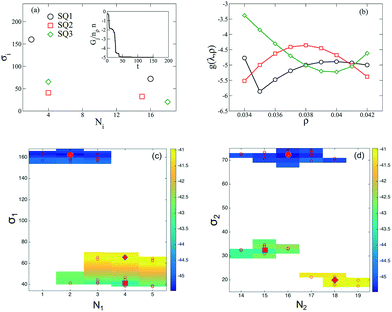
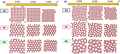
We begin by presenting the details of the results of our optimization scheme when we target a square lattice over a range of NP areal densities ρ ∈ [0.034, 0.042]. From the set of optimized grafting densities generated in our CMA-ES implementation, three representative designs denoted as SQ1, SQ2 and SQ3 are selected and plotted in Fig. 1a as Nivs. σi. The SQ1 shown in the black circles has the minimum global fitness function amongst all the generated solutions. For all of the selected solutions, the two optimized chain lengths are distributed about N1 ≈ 3 and N2 ≈ 16 (Fig. 1c and d), while the variance in the grafting density is significant amongst the solutions. The inset to Fig. 1a plots the scaled fitness function, Gj(t) for the solution in blacks circle as a function CMA iteration, t. The function quickly decreases and reaches a plateau after about 50 iterations indicating a fast convergence rate. We further investigate the quality of the selected solutions over the range of ρ by presenting the fitness function, g(λj, ρ) as a function of ρ in Fig. 1b. The profiles for the three selected solutions exhibit different non-linear patterns. For SQ1 and SQ3, local minimum can be identified in the profiles at about ρ = 0.035 and 0.040, respectively while the profile from SQ2 exhibits a concave shape and a maximum at ρ = 0.038. Overall, the profile from SQ1 has the lower values over the range of ρ, as we expected. Finally, the convergence of the optimized designs is examined. According to the heat-maps of Gj/n in Fig. 1c and d, the majority of designs from trials j ∈ [1, 50] with lowest values of Gj/n concentrates about the SQ1 (the star in the center of dark blue region on each figures), which indicates a good convergence of the proposed optimization scheme, although less stable minima were also located (yellow and green regions) with nearby grafting densities and chain lengths.We next tested whether the converged solutions were able to spontaneously form the targeted structure by performing HPF simulations with 100 NPs with the grafting design from the solutions. Here, the assembled NP configurations from two types of HPF simulations are presented. The first type coming from simulations with initial NP configurations biased to square lattices (Fig. 2a), exhibits a defect-free square lattice pattern for the NPs with design SQ1 over all the entire range of ρ. For the other two sample converged designs SQ2 and SQ3, the assembled structure become less ordered for the highest density test, where ρ = 0.042. Similar results can be observed in the results from simulations with random initial NP configurations (Fig. 2b), though generally speaking more defects are present. The assembled structures from NPs with the design from SQ1 also exhibit square lattice pattern at ρ = 0.042, although the defects in the form of grain boundaries begin to appear in the pattern. However, for the NPs with the designs from SQ2 and SQ3, the square lattice pattern can only be observed in the lowest ρ value at 0.034. It is interesting that the defective systems, SQ2 and SQ3, adopt local motifs with five-particle symmetries, though long-range order is clearly lacking.
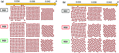 | ||
| Fig. 2 Snapshots from HPF simulations on the three selected designs in Fig. 1a where the simulations were initialized with (a) biased and (b) random initial configurations, respectively. The grafted chains are not shown for clarity. | ||
3.2 Optimization of open NP lattices
Having demonstrated the optimization scheme on the formation of a square lattice, we proceed to apply the scheme to design honeycomb (HC) and kagome (KG) lattices in addition to the square (SQ) lattices described above. The optimized designs are shown in Fig. 3, where we see that the HC design includes two longer grafted chains but much smaller grafting densities. For the KG design, the two grafting chains show the largest disparity in the chain lengths, where the longer chain is about ten times longer than smaller one. The designs shown in the inset are generated from the same optimization scheme, though they were generated at a single value of ρ = 0.038. These designs optimized at a single density are found to have similar chain lengths compared to when an extended range of ρ is used.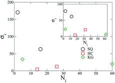 | ||
| Fig. 3 Optimized design for NPs forming SQ, HC, and KG lattices over the range, ρ ∈ [0.034, 0.042] (main figure) and ρ = 0.038 (inset). | ||
The above designs are tested using HPF simulations with multiple NPs in the system. The assembled configurations shown in Fig. 4a were produced from HPF simulations with initial configuration biased to the target lattice. The NPs using SQ and HC design are found to assemble into defect-free square and honeycomb lattices at all three values of ρ, while defects are observed in the KG lattice. If the initial condition in HPF simulations is changed to a random configuration, as presented in Fig. 4b the NPs using the SQ design still predominantly show a square lattice, though defects and grain boundaries do emerge. However, the NPs using the HC design exhibit localized defects at small and intermediate values of ρ. For the NPs using the KG design, we do not observe well-ordered KG structures at all the values of ρ. Both the KG and HC lattices do provide an open structure, which could be advantageous for 2D assemblies.
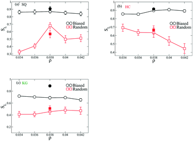
To quantify the ordering of the above shown assembled structures, we construct a lattice order parameter SL based on the distribution of angles formed by three adjacent NPs in the structures. Briefly, we calculate the ratio of the number of angles ϕ distributed within a small range (δϕ = ±5 degree) about the characteristic angles in the lattices relative to the total number of angles; the ratio of the number centered about their characteristic angles to the total defines SL. For example, square lattice has two characteristic angles at 90 and 180 degrees such that angles distributed in [85 95] and [175 185] will be accounted to the numerator of the ratio. This ratio has the limits of 1 when the NPs assemble into a perfect lattice and 2δϕ/180 when the angle distribution is completely random. The analyzed SL values from the above structures are presented in Fig. 5. Amongst all the types of NP designs, the structure coming from biased initial configurations exhibit higher values of SL over the range of ρ compared to these from the random initial configurations. This trend is also observed for the structures coming from NPs using designs optimized just at ρ = 0.038. For NPs with SQ design, the SL in the assembled structure coming from random initial configurations reaches highest value at ρ = 0.038, in the HC design SL decreases as ρ increases, and for the KG design SL is approximately constant.
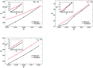
These results demonstrate that the biased states exhibit fewer defects, and we next provide evidence that these configurations are lower free energy states. To approach this, the free energy per NP of the assemble structures is quantified from three contributions: the entropic energy from the grafted chains, Hg, the enthalpic energy from NP-grafting chain interactions, Hw, and the vibrational free energy from NP configurations, Hq. Fig. 6 plots the per NP free energy, F, of the assembled structures as a function of ρ. We observe that for all lattices considered here the free energy has a smaller value from the simulations with biased initial configuration over the range of ρ. As shown in the insets to the figures here, we also find that the majority of free energy contribution arises from the entropy of the grafted chain, Hg. Based on this set of results we would argue that the assembled structures from the biased initial configurations are energetically more favored states, and the entropy of the grafted polymers plays a dominant role in driving the system into each configuration.
3.3 Anisotropic grafted chain distributions and multi-body effects
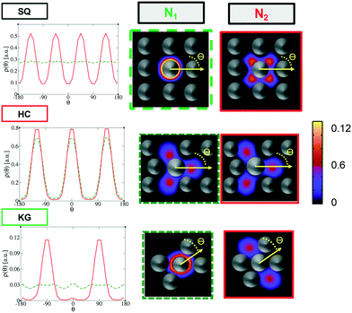
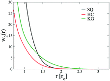
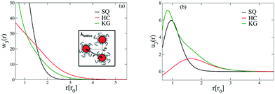
The above free energy analysis indicates the importance of the entropic contribution from grafted chains, which is expected to correlate with the grafted chain conformations. Therefore, in this section we explore the grafted chain distribution about the NP cores and attempt to answer how the distribution would affect the interparticle interactions. We first investigate the density map of the grafted chains around a single NP in the lattice as shown in Fig. 7. The distribution of the shorter grafted chains (denoted N1) shows three- and six-folds rotational symmetry in the HC and KG designs while in SQ design where N1 has the shortest length, the grafted chain distributions are generally homogenous around the NP. The anisotropy becomes pronounced in the longer grafted chains, N2, where four-, three-, and two-fold symmetry can observed. From the scaled angular density profiles, (θ), we notice that the two types of grafted chains have a very similar angular distribution in the HC design. In contrast, the angular distribution in the SQ and the HG designs are quite distinct.We next examine the NP–NP interactions through the two-body potential of mean force (w2(r)) between isolated NPs. As shown in Fig. 8, all the potentials of mean force exhibit a purely convex, repulsive nature when the NP–NP distance, r, is below the equilibrium distance in the lattice, r0. Interestingly, we observe that w2(r) remains finite even at distances where r is approximately two times r0. The importance of these long-range effects becomes even more pronounced when we investigate the multi-body interactions. To illustrate this point, the total three-body potential of mean force, w3(r), is calculated. The results show that w3(r) exhibits a finite strength beyond 2r0 for each optimized design. Specifically, for the w3(r) from the HC and the KG designs, the interaction range can exceed 4r0 (Fig. 9a). We further isolate the three body component of the potential by subtracting off the two-body potential between the three particles involved, u3(r) = w3(r) − 2w2(r) − w2(r0); the result is shown in Fig. 9b. It is interesting to observe that the potential shows a non-monotonic change when r increases across the equilibrium distance r0. In particular, u3(r) from SQ design exhibits a peak intensity right at the position where the three particles would form an equilateral triangle. This local maximum in the potential indicates that the three body interaction destabilizes triangle structure in the assembly of NPs, which likely leads to the stabilization of the square lattice.
4 Conclusion
In this manuscript, an optimization approach is presented to solve the inverse design problem for systems with some chemical detail, namely polymer-grafted nanoparticles (gNPs) grafted with two distinct grafted polymer chain lengths. Our approach uses an evolutionary optimization scheme (CMA-ES) on a 2D field-theoretic NP model to search for the optimized NP design on a unit cell of the lattice, and our designs are verified on multi-NP systems where we allow the particles to thermally sample their configurations. We find that in many cases, our gNPs self-assemble into the targeted structure over the range of density, though defects are often present at the edges of the density range. Our investigation on the interactions amongst NPs with the optimized design in the target lattice highlights the importance of many-body effects, which serve to prevent the NPs from assembling into competing lattices and thus might contribute to the formation of the targeted lattice.We take the methods and results presented here as a promising first step towards designing the chemistry of nanoparticles that could be designed experimentally for targeted self-assembly, but there are several assumptions that need to be relaxed in future work. The first one is the definition of uniform grafting density in the hSCFT NP model, which might become an unphysical assumption when the grafting density is small and the discrete nature of the grafting sites becomes important. It is well-known that grafted particles at low graft densities exhibit anisotropic interactions and assemblies.18 One strategy for addressing this issue can be to adopt the dynamic mean field framework introduced by the authors39 where the grafting sites on the NP surface are treated explicitly, though this loses direct access to the free energy. In addition, the polymer chain conformations are treated entirely at the mean-field level in a θ solvent, and testing the fluctuation effects and the influence of solvent quality and the effects of other enthalpic interactions remains an outstanding issue.
Conflicts of interest
There are no conflicts to declare.Acknowledgements
The authors gratefully acknowledge support from the National Science Foundation through award CBET-1510635. This work used the Extreme Science and Engineering Discovery Environment (XSEDE) through allocation TG-DMR150034, which is supported by NationalScience Foundation grant number ACI-1548562.References
- H. A. Atwater and A. Polman, Nat. Mater., 2010, 9, 205–213 CrossRef CAS PubMed.
- M. J. Hore and R. J. Composto, Curr. Opin. Chem. Eng., 2013, 2, 95–102 CrossRef.
- M. J. A. Hore and R. J. Composto, Macromolecules, 2014, 47, 875–887 CrossRef CAS.
- Y. Yan, S. C. Warren, P. Fuller and B. A. Grzybowski, Nat. Nanotechnol., 2016, 11, 603–608 CrossRef CAS PubMed.
- B. Rasin, H. Chao, G. Jiang, D. Wang, R. A. Riggleman and R. J. Composto, Soft Matter, 2016, 12, 2177–2185 RSC.
- M. C. Rechtsman, F. H. Stillinger and S. Torquato, Phys. Rev. Lett., 2005, 95, 228301 CrossRef PubMed.
- M. Rechtsman, F. Stillinger and S. Torquato, Phys. Rev. E: Stat., Nonlinear, Soft Matter Phys., 2006, 73, 011406 CrossRef PubMed.
- É. Marcotte, F. H. Stillinger and S. Torquato, Soft Matter, 2011, 7, 2332 RSC.
- A. Jain, J. R. Errington and T. M. Truskett, Soft Matter, 2013, 9, 3866 RSC.
- M. Z. Miskin and H. M. Jaeger, Nat. Mater., 2013, 12, 326–331 CrossRef CAS PubMed.
- J. Qin, G. S. Khaira, Y. Su, G. P. Garner, M. Miskin, H. M. Jaeger and J. J. de Pablo, Soft Matter, 2013, 9, 11467 RSC.
- G. S. Khaira, J. Qin, G. P. Garner, S. Xiong, L. Wan, R. Ruiz, H. M. Jaeger, P. F. Nealey and J. J. de Pablo, ACS Macro Lett., 2014, 3, 747–752 CrossRef CAS.
- A. Jain, J. R. Errington and T. M. Truskett, Phys. Rev. X, 2014, 4, 031049 Search PubMed.
- W. D. Piñeros, M. Baldea and T. M. Truskett, J. Chem. Phys., 2016, 144, 084502 CrossRef PubMed.
- S. T. Milner, T. Witten and M. Cates, Macromolecules, 1988, 21, 2610–2619 CrossRef CAS.
- D. Meng, S. K. Kumar, J. M. D. Lane and G. S. Grest, Soft Matter, 2012, 8, 5002 RSC.
- D. M. Trombly and V. Ganesan, J. Chem. Phys., 2010, 133, 154904 CrossRef PubMed.
- P. Akcora, H. Liu, S. K. Kumar, J. Moll, Y. Li, B. C. Benicewicz, L. S. Schadler, D. Acehan, A. Z. Panagiotopoulos, V. Pryamitsyn, V. Ganesan, J. Ilavsky, P. Thiyagarajan, R. H. Colby and J. F. Douglas, Nat. Mater., 2009, 8, 354–359 CrossRef CAS PubMed.
- S. K. Kumar, N. Jouault, B. Benicewicz and T. Neely, Macromolecules, 2013, 46, 3199–3214 CrossRef CAS.
- A. Jayaraman and K. S. Schweizer, Macromolecules, 2008, 41, 9430–9438 CrossRef CAS.
- V. Pryamtisyn, V. Ganesan, A. Z. Panagiotopoulos, H. Liu and S. K. Kumar, J. Chem. Phys., 2009, 131, 221102 CrossRef PubMed.
- N. A. Mahynski and A. Z. Panagiotopoulos, J. Chem. Phys., 2015, 142, 074901 CrossRef PubMed.
- T. B. Martin, P. M. Dodd and A. Jayaraman, Phys. Rev. Lett., 2013, 110, 018301 CrossRef PubMed.
- T. B. Martin and A. Jayaraman, Macromolecules, 2013, 46, 9144–9150 CrossRef CAS.
- Y. Li, P. Tao, A. Viswanath, B. C. Benicewicz and L. S. Schadler, Langmuir, 2013, 29, 1211–1220 CrossRef CAS PubMed.
- Y. Li, T. M. Krentz, L. Wang, B. C. Benicewicz and L. S. Schadler, ACS Appl. Mater. Interfaces, 2014, 6, 6005–6021 CAS.
- J. Koski, H. Chao and R. A. Riggleman, Chem. Commun., 2015, 51, 5440–5443 RSC.
- B. Lin, T. B. Martin and A. Jayaraman, ACS Macro Lett., 2014, 3, 628–632 CrossRef CAS.
- N. Nair and A. Jayaraman, Macromolecules, 2010, 43, 8251–8263 CrossRef CAS.
- A. Walther, K. Matussek and A. H. E. Müller, ACS Nano, 2008, 2, 1167–1178 CrossRef CAS PubMed.
- C. E. Estridge and A. Jayaraman, ACS Macro Lett., 2015, 4, 155–159 CrossRef CAS.
- N. Hansen, S. D. Müller and P. Koumoutsakos, Evol. Comput., 2003, 11, 1–18 CrossRef PubMed.
- N. Hansen, in Towards a new evolutionary computation. Advances on estimation of distribution algorithms, ed. J. Lozano, P. Larranaga, I. Inza and E. Bengoetxea, Springer, 2006, pp. 75–102 Search PubMed.
- S. Sides, B. Kim, E. Kramer and G. Fredrickson, Phys. Rev. Lett., 2006, 96, 250601 CrossRef PubMed.
- J. Koski, H. Chao and R. A. Riggleman, J. Chem. Phys., 2013, 139, 244911 CrossRef PubMed.
- M. C. Villet and G. H. Fredrickson, J. Chem. Phys., 2014, 141, 224115 CrossRef PubMed.
- G. H. Fredrickson, The Equilibrium Theory of Inhomogeneous Polymers, Oxford University Press, New York, 2006 Search PubMed.
- D. A. McQuarrie, Statistical Mechanics, University Science Books, Sausalito, CA, 2000 Search PubMed.
- H. Chao, J. Koski and R. A. Riggleman, Soft Matter, 2017, 13, 239–249 RSC.
| This journal is © The Royal Society of Chemistry 2018 |

