 Open Access Article
Creative Commons Attribution 3.0 Unported Licence
Scalable thin-layer membrane reactor for heterogeneous and homogeneous catalytic gas–liquid reactions†
Yiming
Mo‡
 ,
Joseph
Imbrogno‡
 ,
Haomiao
Zhang
 and
Klavs F.
Jensen
 *
*
Department of Chemical Engineering, Massachusetts Institute of Technology, Cambridge, MA 02139, USA. E-mail: kfjensen@mit.edu
First published on 23rd July 2018
Abstract
Catalytic gas–liquid reactions have potential as environmentally benign methods for organic synthesis, particularly hydrogenation and oxidation reactions. However, safety and scalability are concerns in the application of gas–liquid reactions. In this work, we develop and demonstrate a scalable, sustainable, and safe thin-layer membrane reactor for heterogeneous Pd-catalyzed hydrogenations and homogenous Cu(I)/TEMPO alcohol oxidations. The implementation of a Teflon amorphous fluoroplastic (AF) membrane and porous carbon cloth in the membrane reactor provides sufficient gas–liquid mass transfer to afford superior performance compared to conventional packed-bed or trickle-bed reactors. The membrane separates the gas from the liquid, which avoids the formation of explosive mixtures for oxygenation reactions and simplifies the two-phase hydrodynamics to facilitate scale-up by stacking modules, while significantly reducing gas consumption. In addition, 3-dimensional simulations deliver insights into the mass transfer and hydrodynamic behavior to inform optimal membrane reactor design and operation.
Introduction
Among numerous pharmaceutical transformations, gas–liquid reactions, such as hydrogenation,1 aerobic oxidation,2,3 and ozonolysis,4 show attractive atom economy in comparison to other chemical transformations. For example, direct hydrogenation of pharmaceutical precursors with hydrogen gas outpaces other costly sacrificial reducing reagents, such as hydrides (LiAlH4 and NaBH4) or borane reagents. In addition to atom economy, the general availability of gaseous reagents and facile downstream separation make gas–liquid reactions potential green chemistry processes.5 However, concerns of process efficiency, scalability, and safety of gas–liquid systems create barriers for pharmaceutical applications and this becomes even more challenging when heterogeneous catalysts are present in gas–liquid systems.1,6Over the past decade, continuous flow technology has emerged as a powerful technique to produce active pharmaceutical ingredients (APIs) driven by advantages of continuous technology over conventional batch or semi-batch processes, including steady state operation, enhanced heat and mass transfer rates, reproducibility, and improved safety and process reliability.7–12 These benefits are especially true for gas–liquid reaction systems, where the absence of high-pressure headspace gas and reduced reactor volume of continuous flow reactors significantly improve the safety profiles compared to high-pressure reaction vessels. In addition, the increased interfacial area per volume in flow reactors accelerates multiphase mass transfer rates.
Packed-bed reactors, a common type of gas–liquid reactor, despite their mature development in the petrochemical industry, have not been widely adopted in pharmaceutical manufacturing.13 Zaborenko et al. studied packed-bed reactors of small scale (20 g catalyst), medium scale (120 g catalyst), and pilot scale (1.5 kg catalyst) for successful development of continuous hydrogenation of a pharmaceutical intermediate.13 Yang et al. provided in-depth characterization of the micro-packed-bed reactor to establish a fundamental understanding of the multiphase hydrodynamics and mass transfer properties.1
The complex multiphase hydrodynamics in packed-bed reactors requires extensive understanding of the system behavior across different scales. Additionally, direct contact of gas and liquid is unfavorable for aerobic oxidations due to the formation of flammable oxidant and organic solvent mixtures.6 The low cross-tube heat transfer of packed-bed reactors can also lead to a non-uniform temperature profile for highly exothermic reactions, leaving APIs with temperature-sensitive functional groups at risk for degradation.
Recently, Gavriilidis et al. demonstrated heterogeneously catalyzed benzyl alcohol oxidation in a ceramic membrane packed-bed reactor.14 However, the pressure-driven mechanism of the ceramic membrane has no selectivity over gas and liquid permeation, leading to difficulty in operating under desired two-phase pressure profile. Ley et al. proposed and demonstrated the concept of a tube-in-tube reactor using gas-permeable Teflon amorphous fluoroplastic (AF) membranes for various gas–liquid reactions, including heterogeneous and homogeneous hydrogenation,15 ozonolysis,4 and carboxylation.16 The implementation of Teflon AF membrane (highly permeable to gas phase and impermeable to liquid phase) greatly simplifies the reactor operation compared to ceramic membrane. The capabilities and physical properties of the Teflon AF membrane have been described elsewhere.17–20 Yang et al. used both analytical and numerical methods to understand the behavior of the tube-in-tube reactor, and indicated challenges in scale-up due to radial-diffusion-limited mass transfer.21 The challenge of incorporating heterogeneous catalysts in a tube-in-tube reactor makes it less attractive for a broad category of heterogeneous catalytic gas–liquid reactions.
Thus, an efficient, safe, scalable, and widely applicable continuous flow reactor design for gas–liquid reactions is still desirable for low-volume applications. Here, we present a scalable, sustainable, and safe thin-layer membrane reactor for heterogeneous and homogenous catalytic gas–liquid reactions. The reactor uses a Teflon AF membrane sandwiched between two sheets of thin-layer carbon cloth, which enables superior gas–liquid mass transfer performance. The carbon cloth layer works as a heterogeneous catalyst support, making this reactor design applicable for heterogeneous catalytic gas–liquid reactions. Additionally, nearly all of the gas is consumed by the reaction, removing the need for recycle and increasing the safety of operation by minimizing the amount of gas required. The membrane reactor is demonstrated using common heterogeneous Pd-catalyzed hydrogenations and homogeneous Cu(I)/TEMPO aerobic alcohol oxidations. The membrane reactor is also stackable allowing for scale-up. In-depth modeling of the membrane reactor affords fundamental understanding and design principles for application to various gas–liquid reactions with different kinetics.
Experimental section
Materials and reagents
Woven carbon cloth with palladium and platinum catalyst was purchased from Fuel Cell Store. Teflon AF membrane (40 μm thick) was purchased from Biogeneral. Nitrobenzene, 2-ethyl cinnamate, 10-undecyn-1-ol, benzyl alcohol, 3-phenyl-1-propanol, furfuryl alcohol, tetrakisacetonitrile copper(I) triflate Cu(MeCN)4(OTf), 2,2′-bipyridine, 1-methylimidazole (NMI), and (2,2,6,6-tetramethylpiperidin-1-yl)oxyl (TEMPO) were purchased from Sigma-Aldrich and used without further purification. Hydrogen (99.999%), oxygen (99.99%), and nitrogen (99.999%) were purchased from Airgas.Thin-layer membrane reactor design
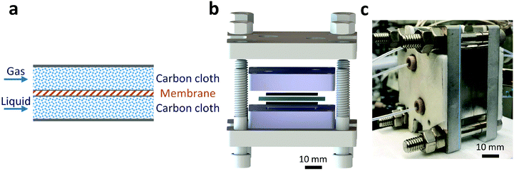
A Teflon AF membrane was sandwiched between two sheets of woven carbon cloth (Fig. 1a) with the gas and liquid phases flowing separately through the two porous carbon cloth layers. The unique property of Teflon AF membranes (highly permeable to gas phase and impermeable to liquid phase) offers the capability of separating the two phases while allowing gas to diffuse through the membrane into the liquid phase. The design was engineered to minimize the thickness of the combined assembly (carbon cloth: 300 μm and Teflon AF membrane: 40 μm) in order to reduce the gas molecule diffusion length and improve the mass transfer performance. The reactor volume of liquid side is 0.05 ml (carbon cloth dimensions: 30 mm × 13 mm × 0.3 mm, porosity: 43%).For demonstration purposes, the membrane reactor (Fig. 1b and c) was fabricated out of aluminum, due to the lower material cost. The membrane reactor can also be coated with perfluoroalkoxy alkane (PFA) or fabricated out of 316 stainless steel for better chemical compatibility. The cartridge heaters inside the reactor combined with a proportional–integral–derivative (PID) temperature controller kept the membrane reactor at the desired reaction temperature.
General membrane reactor operating procedures
Results and discussion
Heterogeneous catalytic hydrogenations
Direct H2 hydrogenation reactions with heterogeneous catalysts are attractive chemical transformations for synthesis because of their atom economy and easy-to-reuse heterogeneous catalysts.5 However, the major challenge for H2 heterogeneous hydrogenations is the poor solubility of H2 in the organic solvent coupled with the slow mass transfer rate from the gas phase to the liquid phase and the catalyst surface. The thin-layer membrane reactor design minimizes the diffusion distance for H2 molecules to the reactive catalyst surface in order to maximize the mass transfer performance. In addition, the membrane reactor was engineered for high pressure operation (tested up to 3.1 MPa), which improves the solubility of H2 in the organic solvent, intensifying the hydrogenation process.To investigate the potential of the membrane reactor in heterogeneous catalysis, we began our investigation with hydrogenation of nitrobenzene 1a to aniline 1b with cost-effective carbon cloth embedded with platinum (Pt) or palladium (Pd) as the heterogeneous catalyst (commercially available from Fuel Cell Store, ∼$1/cm2) (Table 1). The loading of the catalyst on the carbon cloth for both Pt and Pd catalysts was 4 mg cm−2 (based on carbon cloth surface area: width × length). The Pt catalyst was too aggressive, leading to extensive formation of the over-reduction product, while Pd showed a better selectivity towards the desired product 1b compared to Pt (Table 1, entries 1 and 2). Increasing the residence time from 0.5 min to 1 min did not show significant improvement of yield of 1b (Table 1, entries 2 and 3).
With the optimal catalyst (Pd), the heterogeneous catalytic hydrogenation scope was expanded to other substrates (Table 2). The reduction of C–C double and triple bonds is facile under these optimized reaction conditions (full conversion of the starting material). In order to keep the theoretical hydrogen consumption per reagent volume the same, the concentration of the reagent was determined based on the number of hydrogen molecules needed per reagent molecule. All substrates achieved excellent yields with the optimized hydrogenation conditions (Table 2, entries 1–3).
Homogeneous Cu/TEMPO catalyzed aerobic alcohol oxidations
Recent developments of aerobic oxidation reactions provide attractive alternatives to conventional approaches employing stoichiometric oxidants.22–24 However, the practical usage of aerobic oxidation in large-scale synthesis raises safety concerns, namely the formation of explosive mixtures (flammable organic solvents in oxygen). A number of microreactor-based biphasic flow implementations of aerobic oxidation improve the safety profile by accurately controlling oxygen flow in the microchannels.25,26 However, the explosive mixtures are still present in the microreactor system. Tube-in-tube membrane reactors show great potential to avoid the formation of explosive mixtures, but still have inherent scalability issues for large-scale synthesis.21,27 Implementing the thin-layer membrane reactor designed in this work offers the opportunity to make the aerobic oxidation reactions both safe and scalable for industrial applications.Instead of using a catalyst-embedded carbon cloth layer, pristine carbon cloth was installed in the membrane reactor, along with the same Teflon AF membrane to accommodate the homogeneous catalytic aerobic oxidation. Cu/TEMPO catalyzed oxidation of alcohols is an efficient approach to selective aldehyde synthesis.22 This reaction was demonstrated to have first-order kinetics on oxygen concentration in the solvent, which directly corresponds to the oxygen pressure in the gas phase. The ability to handle high pressures in the membrane reactor would intensify this reaction by orders of magnitude compared to batch processing. Meanwhile, the Teflon AF membrane separates the oxygen and organic solvent to circumvent the formation of explosive mixtures.
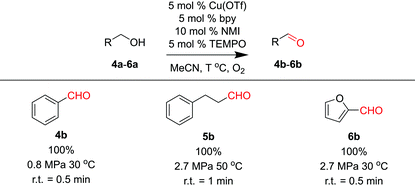
Three substrates (4a–6a) were examined in the membrane reactor with optimized conditions, and all products were achieved in excellent yields (Table 3). The residence times required to reach full conversion were around 1 min, significantly shorter than the several-hour reaction times required under batch conditions.22
| a 0.2 M alcohol substrate with 0.05 equiv. Cu(OTf), 0.05 equiv. 2,2′-bipyridyl (bpy), 0.1 equiv. 1-methylimidazole (NMI), and 0.05 equiv. TEMPO dissolved in MeCN. |
|---|
|
Gas purge for oxygenation reactions
Even though the explosive mixture of liquid organic solvents and oxygen is avoided in the membrane reactor for oxygenation reactions, the organic solvent vapors could potentially penetrate through the Teflon AF membrane to the gas side, which raises safety concerns for large-scale applications. Unlike hydrogenation reactions in the membrane reactor, where the gas side outlet is plugged to reduce the unnecessary hydrogen consumption, an additional oxygen purge stream is required to avoid the accumulation of organic solvent vapors in the gas side, which could exceed lower explosive limits under certain reaction conditions.In order to ensure safe operation of the membrane reactor for reactions involving oxygen, the required oxygen purge stream flowrate needed to keep the solvent vapor concentration under the lower explosive limit (LEL) was calculated for various reaction temperatures and organic solvents. Since the LEL data of organic solvents in pure oxygen are rarely available, the approach developed by Chen28 for estimating the LEL in pure oxygen with the LEL in air was used. The gas purge stream flowrate can be obtained using the permeability of organic solvent vapors through the Teflon AF membrane29,30 and LEL in pure oxygen (eqn (1)) (see ESI† for detailed derivations).
 | (1) |
 | (2) |
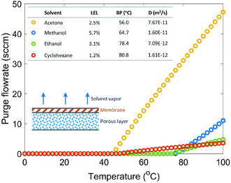
Fig. 2 shows the required gas purge stream flowrates for four solvents under various reaction temperatures with a safety ratio of 0.5 (0.5 is selected as a medium value between 0 and 1, and the actual value can be determined based on desired safety level). Reaction temperature plays an important role in determining the required purge stream, since temperature has an impact on the diffusion coefficient, saturated solvent vapor pressure, and solvent solubility in membrane. For all solvents studied, a purge stream is not required if the reaction is carried out under 40 °C. Acetone requires a very large purge stream to keep the solvent vapor concentration under Csol due to its low LEL, low boiling point and high diffusion coefficient. Cyclohexane, even with the lowest LEL, requires a small purge stream because of its high boiling point and low diffusion coefficient. Methanol and ethanol, with relatively high LEL values, high boiling points, and low diffusion coefficients, require no purge stream up to 75 °C, appearing to be the two safest solvents among the solvents studied.
For oxygenation reactions, implementing a safe solvent (e.g. methanol and ethanol) and operating under a low reaction temperature are essential to improve the safety profile of the membrane reactor, otherwise a purge stream is required to avoid the accumulation of the penetrated organic solvent vapor in the gas side.
Membrane reactor design optimization
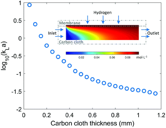
Gas molecules have such a high permeability through the thin Teflon AF membrane that the dominant gas mass transfer resistance is in the liquid layer.21 Hence, the mass transfer performance of the membrane reactor mainly depends on the thickness of the carbon cloth layer, which also determines the reactor volume if the same membrane area is used. A thin carbon cloth layer is favourable when the reaction is mass transfer limited, while kinetically limited reactions would require a thicker carbon cloth layer (large reactor volume) to increase the residence time. In order to maximize the productivity of the membrane reactor with the same membrane area, the optimal thickness of the carbon cloth layer needs to be determined according to relative ratio of mass transfer rate and reaction rate.Understanding and calculating the mass transfer coefficient kLa in the membrane reactor provides the basis for comparison with other typical gas–liquid–solid reactor configurations (e.g. trickle-bed or packed-bed reactors). COMSOL simulation of hydrogen mass transfer into ethanol under various carbon cloth thicknesses was conducted. As shown in Fig. 3, the mass transfer performance strongly depends on the thickness of the carbon cloth layer ranging across two orders of magnitude. The hydrogen concentration profile in the membrane is nearly homogeneous indicating negligible mass transfer resistance in the membrane, which is consistent with reported results.21 The thin-layer membrane reactor with a carbon cloth thickness of 0.3 mm used in the previous experiments has a kLa value of 0.3 s−1. Even a relatively thick carbon cloth (>1 mm) has a kLa value on the order 10−2–10−1 s−1, which is comparable to the kLa values (0.01–0.08 s−1) reported for conventional laboratory-scale trickle-bed reactors.31 In addition to the superior mass transfer performance, it is also tunable by changing the carbon cloth thickness according to the kinetics of the reaction system.
The porous structure of the carbon cloth helps the flow distribution across the reactor and makes the flow profile close to that of plug flow (Fig. S8†), which simplifies the hydrodynamics making it possible to understand the system with a one-dimensional (1D) model. The 1D model identifies two dimensionless numbers, first Damköhler number (DaI) and second Damköhler number (DaII), that control the reaction outcome of the membrane reactor (see ESI† for detailed derivation).
| DaI = kτ | (3) |
 | (4) |
COMSOL 3D simulation illustrates the dependence of reaction outcome on different values of DaI and DaII (Fig. 4). When DaII ≪ 1, indicating the reaction rate is much slower than the diffusion rate, the reaction conversion in the membrane reactor is insensitive to the value of DaII, corresponding to the “reaction limited” regime in Fig. 4. In contrast, the dependence of the reaction conversion on DaII becomes much stronger when DaII > 1, corresponding to the “mass transfer limited” regime, where an efficient mass transfer configuration is beneficial for reaction conversion. Thus, identifying the ratio between mass transfer time scale and reaction time scale is essential for choosing the optimal membrane reactor design (i.e. carbon cloth layer thickness) in order to balance the trade-off between productivity and reactor fabrication cost.
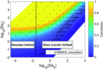 | ||
| Fig. 4 COMSOL simulation of hydrogenation of nitrobenzene with ethanol as solvent in the membrane reactor. The residence time, carbon cloth thickness, and reaction kinetic constant are varied to obtain different values of DaI and DaII. Hydrogenation pressure: 2.8 MPa. Carbon cloth layer dimension: length (30 mm) × width (12 mm) × thickness (0.05 mm–3 mm). Membrane thickness: 40 μm. The reaction kinetics are available from reported literature, and changing the kinetic constant corresponds to the change of catalyst loading or reaction temperature.32 | ||
Scale-up of thin-layer membrane reactor
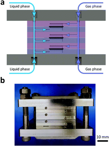
The complex process needed to scale up conventional trickle-bed or packed-bed reactors is mainly attributed to the change in multiphase hydrodynamics, mass, and heat transfer properties across different scales.13 The simplified fluid hydrodynamics in the thin-layer membrane reactor offers the opportunity for straightforward scale-up with a stackable design. The stackable design maintains a fixed heat and mass transfer distance (carbon cloth thickness) while increasing the reactor size laterally and in parallel, resulting in preserved heat and mass transfer advantages of the single-layer membrane reactor while meeting the required productivity. As shown in Fig. 5a, the main channels of a 3-layer stacked membrane reactor distribute or collect gas streams and liquid streams into or from each layer. The design of distribution channels follows barrier-based uniform flow distribution criteria.33,34Fig. 5b shows an assembled 3-layer membrane reactor, and each layer has identical inner dimensions as the single-layer membrane reactor. If the reaction is highly exothermic requiring fast heat dissipation, multiple cooling layers could be implemented between two individual layers periodically to maximize the heat dissipation rate (Fig. S12†).In order to enable direct scale-up from a single-layer to multiple-layers, it is essential to have identical flow distribution across each layer in the stacked membrane reactor. Besides the optimized distribution channel design shown in Fig. 5a, the porous carbon cloth in each layer also plays an important role in unifying flow distribution. COMSOL hydrodynamics simulations (Fig. S13 and S14†) illustrate the difference of flow distribution with and without carbon cloth for 3-layer and 10-layer membrane reactors (Table 4). Compared to the case without carbon cloth, the porous structure of the carbon cloth adjusts the flow pressure drop profile, which helps to maintain an even distribution of flow from the main channel. This effect becomes more important as an increasing number of layers are stacked together.
The 3-layer membrane reactor (Fig. 5b) was demonstrated using the hydrogenation of ethyl cinnamate (2a). Using identical reaction conditions as the single-layer membrane reactor, (Table 2, entry 2) except for 0.3 ml min−1 liquid flowrate (0.1 ml min−1 in the single-layer membrane reactor), the 3-layer membrane reactor was able to produce 1.9 g h−1 of the hydrolyzed product in 91% yield continuously, tripling the hydrogenation productivity without any reaction condition optimization.
Conclusion
This work presented the development and experimental validation of a thin-layer membrane reactor with commonly used heterogeneous Pd-catalyzed hydrogenations and homogeneous Cu(I)/TEMPO aerobic alcohol oxidations. The unique structure implemented a Teflon AF membrane and porous carbon cloth in the membrane reactor to separate the gas from the liquid, simplifying the multiphase hydrodynamics for predictable reactor performance and straightforward scale-up. The thin-layer design minimized mass transfer resistance in gas–liquid systems. Optimizing the carbon cloth thickness according to the reaction kinetics balanced the trade-off between reactor manufacturing cost and productivity. Both the membrane design and the detailed guidelines for safe operation of oxygenation reactions provided in this work could potentially accelerate the adoption of oxygen and hydrogen as cheap, green reagents in industrial applications. In addition, a stackable membrane design demonstrated a possible scale-up strategy.Conflicts of interest
There are no conflicts to declare.Acknowledgements
We thank the Novartis-MIT Center for Continuous Manufacturing for financial support.References
- C. Yang, A. R. Teixeira, Y. Shi, S. C. Born, H. Lin, Y. L. Song, B. Martin, B. Schenkel, M. P. Lachegurabi and K. F. Jensen, Green Chem., 2018, 20, 886–893 RSC.
- D. P. Hruszkewycz, K. C. Miles, O. R. Thiel and S. S. Stahl, Chem. Sci., 2017, 8, 1282–1287 RSC.
- H. P. L. Gemoets, Y. Su, M. Shang, V. Hessel, R. Luque and T. Noël, Chem. Soc. Rev., 2015, 45, 83–117 RSC.
- M. O'Brien, I. R. Baxendale and S. V. Ley, Org. Lett., 2010, 12, 1596–1598 CrossRef PubMed.
- J. S. Carey, D. Laffan, C. Thomson and M. T. Williams, Org. Biomol. Chem., 2006, 4, 2337–2347 RSC.
- P. M. Osterberg, J. K. Niemeier, C. J. Welch, J. M. Hawkins, J. R. Martinelli, T. E. Johnson, T. W. Root and S. S. Stahl, Org. Process Res. Dev., 2015, 19, 1537–1543 CrossRef PubMed.
- T. Tsubogo, H. Oyamada and S. Kobayashi, Nature, 2015, 520, 329–332 CrossRef PubMed.
- C. Wiles and P. Watts, Green Chem., 2012, 14, 38–54 RSC.
- Y. Mo and K. F. Jensen, React. Chem. Eng., 2016, 1, 501–507 RSC.
- A. Adamo, R. L. Beingessner, M. Behnam, J. Chen, T. F. Jamison, K. F. Jensen, J.-C. M. Monbaliu, A. S. Myerson, E. M. Revalor, D. R. Snead, T. Stelzer, N. Weeranoppanant, S. Y. Wong and P. Zhang, Science, 2016, 352, 61–67 CrossRef PubMed.
- J. Imbrogno, L. Rogers, D. A. Thomas and K. F. Jensen, Chem. Commun., 2017, 54, 70–73 RSC.
- Y. Mo, H. Lin and K. F. Jensen, Chem. Eng. J., 2018, 335, 936–944 CrossRef.
- N. Zaborenko, R. J. Linder, T. M. Braden, B. M. Campbell, M. M. Hansen and M. D. Johnson, Org. Process Res. Dev., 2015, 19, 1231–1243 CrossRef.
- A. Constantinou, G. Wu, A. Corredera, P. Ellis, D. Bethell, G. J. Hutchings, S. Kuhn and A. Gavriilidis, Org. Process Res. Dev., 2015, 19, 1973–1979 CrossRef.
- M. O'Brien, N. Taylor, A. Polyzos, I. R. Baxendale and S. V. Ley, Chem. Sci., 2011, 2, 1250–1257 RSC.
- A. Polyzos, M. O'Brien, T. P. Petersen, I. R. Baxendale and S. V. Ley, Angew. Chem., Int. Ed., 2011, 50, 1190–1193 CrossRef PubMed.
- I. Pinnau and L. G. Toy, J. Membr. Sci., 1996, 109, 125–133 CrossRef.
- P. Bernardo, E. Drioli and G. Golemme, Ind. Eng. Chem. Res., 2009, 48, 4638–4663 CrossRef.
- J. H. Lowry, J. S. Mendlowitz and N. S. (Mani) Subramanian, Opt. Eng., 1992, 31, 1982–1986 CrossRef.
- P. R. Resnick and W. H. Buck, in Fluoropolymers 2, Springer, Boston, MA, 2002, pp. 25–33 Search PubMed.
- L. Yang and K. F. Jensen, Org. Process Res. Dev., 2013, 17, 927–933 CrossRef.
- J. M. Hoover and S. S. Stahl, J. Am. Chem. Soc., 2011, 133, 16901–16910 CrossRef PubMed.
- J. M. Hoover, B. L. Ryland and S. S. Stahl, ACS Catal., 2013, 3, 2599–2605 CrossRef PubMed.
- J. M. Hoover, B. L. Ryland and S. S. Stahl, J. Am. Chem. Soc., 2013, 135, 2357–2367 CrossRef PubMed.
- X. Ye, M. D. Johnson, T. Diao, M. H. Yates and S. S. Stahl, Green Chem., 2010, 12, 1180–1186 RSC.
- J. E. Steves, Y. Preger, J. R. Martinelli, C. J. Welch, T. W. Root, J. M. Hawkins and S. S. Stahl, Org. Process Res. Dev., 2015, 19, 1548–1553 CrossRef.
- J. F. Greene, Y. Preger, S. S. Stahl and T. W. Root, Org. Process Res. Dev., 2015, 19, 858–864 CrossRef.
- C.-C. Chen, Ind. Eng. Chem. Res., 2011, 50, 10283–10291 CrossRef.
- A. M. Polyakov, L. E. Starannikova and Y. P. Yampolskii, J. Membr. Sci., 2004, 238, 21–32 CrossRef.
- A. M. Polyakov, L. E. Starannikova and Y. P. Yampolskii, J. Membr. Sci., 2003, 216, 241–256 CrossRef.
- M. H. Al-Dahhan, F. Larachi, M. P. Dudukovic and A. Laurent, Ind. Eng. Chem. Res., 1997, 36, 3292–3314 CrossRef.
- V. Holler, D. Wegricht, I. Yuranov, L. Kiwi-Minsker and A. Renken, Chem. Eng. Amp. Technol., 2000, 23, 251–255 CrossRef.
- N. de Mas, A. Günther, T. Kraus, M. A. Schmidt and K. F. Jensen, Ind. Eng. Chem. Res., 2005, 44, 8997–9013 CrossRef.
- M. Al-Rawashdeh, F. Yue, N. G. Patil, T. A. Nijhuis, V. Hessel, J. C. Schouten and E. V. Rebrov, AIChE J., 2014, 60, 1941–1952 CrossRef.
Footnotes |
| † Electronic supplementary information (ESI) available. See DOI: 10.1039/c8gc01917g |
| ‡ These authors contributed equally to this work. |
| This journal is © The Royal Society of Chemistry 2018 |

