Metal-acid site synergistic catalysis in Ru–ZrO2 toward selective hydrogenation of benzene to cyclohexene†
Received
6th July 2017
, Accepted 19th November 2017
First published on 20th November 2017
Abstract
Ruthenium-based catalysts are one of the most promising candidates toward selective hydrogenation of benzene. In this work, we synthesized a novel core–shell catalyst by coating porous B-doped ZrO2 on the surface of Ru/ZrO2 particles (denoted as Ru/ZrO2@ZrO2-B(x%)), in which the hydrogen dissociation occurs on the inner surface of metal Ru and the acid site of the exterior ZrO2-B(x%) serves as the adsorption site for benzene. The Ru/ZrO2@ZrO2-B(5%) sample demonstrates the optimal synergistic catalysis between metal Ru and the weak/medium-strong Lewis acid site of the ZrO2-B(5%) layer, which promotes the activated adsorption of benzene and desorption of cyclohexene. Therefore, it exhibits the best catalytic performance (benzene conversion: 53.1%; cyclohexene selectivity: 58.8%) without using any additives.
1. Introduction
Cyclohexene is an important chemical raw material, and can be used to produce polycycloylene resin, rubber chemicals and nylon-66.1–3 The production of cyclohexene by selective hydrogenation of benzene has attracted considerable attention due to its advantages in atomic economy and production of fewer by-products.4–6 In particular, ruthenium based catalysts have displayed the best catalytic performance in previous studies,7 but suffer from large loading and the high cost of the noble metal.8 In addition, inorganic additives (e.g., ZnSO4) have been widely used to promote the cyclohexene desorption and inhibit its further hydrogenation, so as to largely enhance the selectivity of cyclohexene.4,9–12 However, the employment of Zn salts leads to environmental pollution and equipment corrosion in industrial operations. Therefore, how to design and prepare a new type of ruthenium-based catalyst, so as to efficiently improve its activity and selectivity without additives, is still an urgent issue and needs deep investigation.
For supported metal catalysts, the synergistic effect of metal-carrier normally plays a crucial role in the catalytic reaction; a sophisticated catalyst design and subtle control over fine structure of active sites could optimize the synergistic effect and thus enhance the catalytic performance.13–15 For the selective hydrogenation of benzene, it is reported that the hydrogen dissociation occurs on the surface of metal Ru; while the acid site of the carrier serves as the activated adsorption and hydrogenation site of benzene. Therefore, the tunability of the acid sites would impose a significant influence on the metal-carrier synergistic effect and the resulting cyclohexene yield. ZrO2, a typical reducible carrier with abundant acid sites, has been widely used as a catalyst carrier in hydrogenation reactions and cracking reactions.16–22 Zong et al.23 reported the tuning of acid sites by doping boron into ZrO2, which greatly improved the selectivity of cyclohexene. However, there is still a lack of understanding on the quantitative study of acid sites and how they affect the activity and selectivity of the reaction. It is essential to identify the respective contribution of the metal Ru and acid sites (type, concentration, strength), and to reveal the intrinsic mechanism of metal-carrier synergistic effect, for the purpose of preparing high performance Ru based catalyst toward selective hydrogenation of benzene.
In our previous work, we developed a double-active site separation strategy in Ru based catalyst: a spatial separation between the active site for hydrogen dissociation (Ru) and for benzene hydrogenation (oxide carrier), in order to inhibit the deep hydrogenation of cyclohexene.24 Herein, we further improve this strategy by optimizing the metal-carrier synergistic effect via tuning the acid sites the of oxide carrier. We prepared a Ru/ZrO2 catalyst encapsulated by a porous B-doped ZrO2 coating (denoted as Ru/ZrO2@ZrO2-B(x%)), for the selective hydrogenation of benzene. TEM images display a core–shell structure, in which the particle size of Ru ranges from 1.0–1.1 nm, and the thickness of the exterior ZrO2-B(x%) coating is 2–4 nm. Catalytic evaluations show that the Ru/ZrO2@ZrO2-B(5%) sample exhibits the best selectivity to cyclohexene (benzene conversion: 53.1%; cyclohexene selectivity: 58.8%). H2-TPD and CO-TPD results demonstrate that H2 can access the encapsulated Ru surface through the porous ZrO2-B(x%) layer, while this is forbidden for the benzene molecule, avoiding the deep hydrogenation of cyclohexene on the highly-active Ru. Furthermore, Py-IR and NH3-TPD show that a balance of a weak/medium-strong Lewis acid site on the surface of Ru/ZrO2@ZrO2-B(5%) plays a key role in the promotion of adsorption of benzene and the desorption of cyclohexene, accounting for the enhanced cyclohexene yield.
2. Experiment section
2.1 Materials
RuCl3·3H2O (Ru wt% = 35–42%), ZrO2 (monoclinic type) (99.99%), ZrOCl2·6H2O (99.9%), hexadecyl trimethyl ammonium bromide (CTAB) (>99.0%), NaOH (>98%), and H3BO3 (>99.5%) were of analytical grade (A.R.) and purchased from Aladdin. Other chemicals, including benzene (>99.9%), cyclohexene (>99.9%), and cyclohexane (>99.9%), were purchased from the Beijing chemical Co., Ltd. Deionized water was used in all the experimental processes without further treatment.
2.2 Preparation of catalysts
2.2.1 Synthesis of Ru/ZrO2 precursor.
The Ru/ZrO2 precursor was prepared by the impregnation method. 2.0 g of ZrO2 was dispersed in deionized water (100 mL) with ultrasonication and then added into a RuCl3·3H2O (3.96 mL, 0.1 M) aqueous solution. Subsequently, the NaOH solution (2 mL, 0.1 M) was added drop by drop to the above mixed solution followed by vigorous stirring for 1 h. The obtained precipitation was separated by centrifugation, washed thoroughly with deionized water until no Cl− was detected, and dried in air at 60 °C for 12 h. Then the sample was reduced in 10% H2 (H2/N2 = 1![[thin space (1/6-em)]](https://www.rsc.org/images/entities/char_2009.gif) :
:![[thin space (1/6-em)]](https://www.rsc.org/images/entities/char_2009.gif) 9, v/v) at 400 °C for 3 h to obtain the Ru/ZrO2 catalyst precursor.
9, v/v) at 400 °C for 3 h to obtain the Ru/ZrO2 catalyst precursor.
2.2.2 Synthesis of Ru/ZrO2@ZrO2-B(x%).
Typically, 0.1 g of obtained Ru/ZrO2 and 0.2 g of cetyltrimethyl ammonium bromide (CTAB) were added into deionized water (100 mL) under ultrasonication for 1 h, followed by dropwise addition of a ZrOCl2·8H2O aqueous solution (20 mL, 0.1 M) at 80 °C with vigorous stirring. Subsequently, H3BO3 was added with vigorous stirring for 12 h. The resulting precipitation was filtered and dried in air at 50 °C for 12 h. Finally, these samples were calcined at 450 °C in air to remove CTAB, and a series of B-doped ZrO2 capped Ru/ZrO2 samples were obtained (denoted as Ru/ZrO2@ZrO2-B(x%)), where x represents the molar ratio of H3BO3. In this work, Ru/ZrO2@ZrO2-B(0%), Ru/ZrO2@ZrO2-B(5%), Ru/ZrO2@ZrO2-B(10%), Ru/ZrO2@ZrO2-B(15%) were obtained by adding 0 g, 0.12 g, 0.24 g, 0.36 g of H3BO3, respectively.
2.3 Catalytic reaction
The catalytic reaction of selective hydrogenation of benzene to cyclohexene was carried out in a Teflon-lined stainless steel autoclave (100 mL) equipped with a magnetic stirrer, according to the same procedure reported in our previous work.24
2.4 Characterization
X-ray diffraction (XRD) was characterized using a Rigadu XRD-6000 X-ray diffractometer with a wavelength of 0.154 nm, and the radiation was Cu Kα. The test conditions were: voltage, 40 kV; current, 40 mA; scanning rate, 10° min−1; and 2θ angle, from 3° to 70°. The transmission electron microscopy (TEM) analysis was carried out on a JEOL JEM-2010 at 200 kV and EDS was performed to analyze the catalyst composition. Pyridine adsorption Fourier-transform infrared (Py-IR) spectra were conducted on a Nicolet 380. The sample (20 mg) was first pressed into a wafer (12 mm in diameter) and then installed in a reaction cell, pretreated with hydrogen at 400 °C for 3 h, and cooled to 150 °C for recording of the background infrared signal. Subsequently, pyridine was introduced into the reaction cell until the adsorption was saturated, then the spectrum was recorded by deducting the background. The nPy was calculated based on the following equation:where A, R and m are the surface area (cm2), radius (cm) and weight (g) of the sample wafer, respectively. H2-TPD, CO-TPD, benzene-TPD (Benz-TPD), cyclohexene-TPD (CHE-TPD) were measured on a Micromeritics ChemiSorb 2920. For the H2-TPD measurement, the sample (100 mg) was placed in a U-shaped quartz tube and heated in a mixed atmosphere of hydrogen/argon (1![[thin space (1/6-em)]](https://www.rsc.org/images/entities/char_2009.gif) :
:![[thin space (1/6-em)]](https://www.rsc.org/images/entities/char_2009.gif) 9, v/v) at 400 °C for 3 h. After cooling down to room temperature, the carrier gas (argon for H2-TPD; helium for CO-TPD, Benz-TPD and CHE-TPD) was purged for 1 h to remove the physically adsorbed H2 on the surface of the sample. Finally, the carrier stream was introduced at a rate of 50 mL min−1 with a heating rate of 10° min−1 for the collection of the desorption signal.
9, v/v) at 400 °C for 3 h. After cooling down to room temperature, the carrier gas (argon for H2-TPD; helium for CO-TPD, Benz-TPD and CHE-TPD) was purged for 1 h to remove the physically adsorbed H2 on the surface of the sample. Finally, the carrier stream was introduced at a rate of 50 mL min−1 with a heating rate of 10° min−1 for the collection of the desorption signal.
3. Results and discussion
3.1 Structural and morphological characterization
In this work, a series of Ru-based catalysts were prepared by coating a porous B-doped ZrO2 layer on the Ru/ZrO2 particles. Fig. 1 displays the XRD patterns of Ru/ZrO2, Ru/ZrO2@ZrO2-B(0%), Ru/ZrO2@ZrO2-B(5%), Ru/ZrO2@ZrO2-B(10%) and Ru/ZrO2@ZrO2-B(15%), respectively. For Ru/ZrO2 (Fig. 1a), the diffraction peaks at 2θ 28.1°, 31.4°, 34.1°, 50.1° are indexed to monoclinic ZrO2 (JCPDS No. 37-1484). No reflection of Ru is observed, which is possibly related to the low concentration and small size of the supported Ru particles. After coating with a B-doped ZrO2 layer, the resulting Ru/ZrO2@ZrO2-B(0%), Ru/ZrO2@ZrO2-B(5%), Ru/ZrO2@ZrO2-B(10%), Ru/ZrO2@ZrO2-B(15%) samples display a rather similar phase structure to Ru/ZrO2, indicating an amorphous coating of B-doped ZrO2 layer on the exterior of Ru/ZrO2.
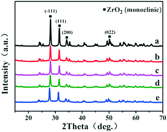 |
| | Fig. 1 XRD patterns of (a) Ru/ZrO2, (b) Ru/ZrO2@ZrO2-B(0%), (c) Ru/ZrO2@ZrO2-B(5%), (d) Ru/ZrO2@ZrO2-B(10%) and (e) Ru/ZrO2@ZrO2-B(15%), respectively. | |
Fig. 2a shows the TEM images of the Ru/ZrO2 sample. Numerous Ru particles with a size of ∼1.0 nm are well-dispersed on the surface of ZrO2. As shown in Fig. 2b, the Ru/ZrO2@ZrO2-B(0%) sample exhibits a clear core–shell structure with a shell thickness of 2–4 nm after the cladding treatment of a ZrO2 layer on the surface of Ru/ZrO2. The lattice fringe of 0.284 nm is identified, corresponding to the (111) plane of monoclinic ZrO2. Fig. 2c–e displays the TEM images of Ru/ZrO2@ZrO2-B(5%), Ru/ZrO2@ZrO2-B(10%) and Ru/ZrO2@ZrO2-B(15%), respectively, all of which give a similar core–shell structure. The B-ZrO2 shell shows an amorphous structure with a thickness of 3–5 nm. Furthermore, Ru 3p XPS spectra of all these samples are shown in Fig. S1.† Two remarkable peaks at 484.7 eV and 426.6 eV are observed for the sample of Ru/ZrO2 (Fig. S1, curve a†), which are attributed to Ru 3p1/2 and Ru 3p3/2, respectively. However, no signal is detected for these core–shell samples (Fig. S1, curves b–e†), indicating that the metallic Ru are entirely embedded by the exterior B–ZrO2 shell. However, it is still difficult to reveal the existence state and distribution of boron in the ZrO2 lattice owing to the technique limitations. We performed DFT calculations to explore the doping of B in ZrO2 lattice (see ESI† for detailed modelling), based on a previous study on the doping of B in TiO2.25 The results show that when one Zr atom is replaced by a B atom, the geometry of the B-doped ZrO2(−111) facet only shows a slight change (Fig. S2†), indicating that the simulated model is energetically favourable. More DFT calculations will be discussed in the following adsorption of benzene and cyclohexene.
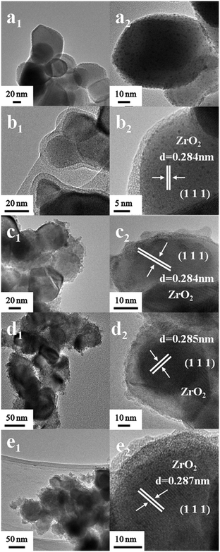 |
| | Fig. 2 HRTEM images of (a) Ru/ZrO2, (b) Ru/ZrO2@ZrO2-B(0%), (c) Ru/ZrO2@ZrO2-B(5%), (d) Ru/ZrO2@ZrO2-B(10%) and (e) Ru/ZrO2@ZrO2-B(15%), respectively. | |
The porous structure of the exterior B-doped ZrO2 layer was studied by hydrogen temperature programmed desorption (H2-TPD) profiles (Fig. 3A). All these samples show two obvious desorption peaks: the low temperature peak is due to the hydrogen desorption from the metallic Ru and the high temperature one is attributed to the desorption of spill over hydrogen on the support. This verifies that the H2 molecule can access the encapsulated Ru surface for dissociation through the porous layer. In particular, the intensity of the high temperature peak enhances gradually along with the increase of the boron-doping amount (from Fig. 3A-b to A-e). The doping of boron would introduce Lewis acid sites into the ZrO2 layer, which facilitates the spill over of hydrogen.26,27 Furthermore, in comparison with the Ru/ZrO2 and Ru/ZrO2@ZrO2-B(0%) samples, the doping of boron in the ZrO2 layer induces a positive shift of the high-temperature desorption peak by 17 °C (from 434 °C to 451 °C). Fig. 3B shows the CO-TPD profiles for Ru/ZrO2 and Ru/ZrO2@ZrO2-B(x%) samples. For the sample of Ru/ZrO2, a remarkable CO desorption peak at 545 °C is observed, which is due to the CO adsorption on the surface of Ru nanoparticles. In contrast, no CO desorption peak can be detected in the entire temperature range for all these four Ru/ZrO2@ZrO2-B(x%) samples. The BET test (Fig. S3†) using the low temperature nitrogen absorption–desorption technique shows both the micropores and mesopores for the sample of Ru/ZrO2@ZrO2-B(5%), indicating that the CO molecule should be accessible to the interior structure. However, no CO-TPD signal is observed, implying the activated adsorption of CO on the interior Ru surface is unfavorable.
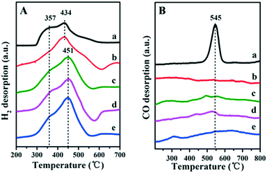 |
| | Fig. 3 (A) H2-TPD and (B) CO-TPD profiles of (a) Ru/ZrO2, (b) Ru/ZrO2@ZrO2-B(0%), (c) Ru/ZrO2@ZrO2-B(5%), (d) Ru/ZrO2@ZrO2-B(10%) and (e) Ru/ZrO2@ZrO2-B(15%), respectively. | |
Fig. 4 illustrates the catalytic performance over Ru/ZrO2@ZrO2-B(x%), with Ru/ZrO2 as a reference sample (110 °C, 5.0 Mpa). Only cyclohexene and cyclohexane are detected as the products for all of these samples. The content of benzene decreases and cyclohexane increases progressively throughout the reaction; while the content of cyclohexene increases first and then decreases, which is in agreement with the well-known behaviour of consecutive reactions. The sample of Ru/ZrO2 shows a maximal cyclohexene selectivity of 18.2% at 20 min, with a benzene conversion of 40.3% (Table 1). In the case of the Ru/ZrO2@ZrO2-B(x%) samples, the catalytic activity at the same time point reduces to some extent, while the maximal selectivity enhances significantly with an exterior ZrO2-B(x%) shell. From x = 0 to x = 15%, the cyclohexene selectivity firstly increases from 35.9% to 58.8% and then decreases to 44.7%. The sample of Ru/ZrO2@ZrO2-B(5%) exhibits the maximum cyclohexene selectivity of 58.8% with a conversion of 53.1%. The results show that the boron content in the exterior shell imposes a remarkable influence on the reaction selectivity.
 |
| | Fig. 4 Time courses of benzene hydrogenation over (a) Ru/ZrO2, (b) Ru/ZrO2@ZrO2-B(0%), (c) Ru/ZrO2@ZrO2-B(5%), (d) Ru/ZrO2@ZrO2-B(10%) and (e) Ru/ZrO2@ZrO2-B(15%), respectively. Reaction conditions: 150 °C, 5.0 Mpa. | |
Table 1 Catalytic performance of different Ru-based catalystsa
| Catalysts |
t
(min) |
Conv.b (%) |
S
CHE
(%) |
Y
CHE
b
(%) |
|
Reaction conditions: catalyst 0.1 g, benzene 10 mL, H2O 20 mL, H2 pressure 5.0 MPa, reaction temperature 150 °C.
The data are provided at the maximum yield of cyclohexene. Conv. = conversion of benzene; SCHE = selectivity to cyclohexene; YCHE = yield of cyclohexene.
|
| Ru/ZrO2 |
20.0 |
40.3 |
18.2 |
7.32 |
| Ru/ZrO2@ZrO2-B(0%) |
70.0 |
60.1 |
35.9 |
21.5 |
| Ru/ZrO2@ZrO2-B(5%) |
40.0 |
53.1 |
58.8 |
31.2 |
| Ru/ZrO2@ZrO2-B(10%) |
30.0 |
45.2 |
48.7 |
22.0 |
| Ru/ZrO2@ZrO2-B(15%) |
30.0 |
48.1 |
44.7 |
21.5 |
3.2 Catalytic performance evaluations
It is well known that the hydrogenation of benzene includes two consecutive steps: the first step is benzene hydrogenation to cyclohexene and the second one is further hydrogenation of the cyclohexene to cyclohexane.28 Previous studies have shown that the first step is a first-order reaction and the second one is a zero order reaction. Therefore, the changes in reaction rate constant (k1 and k2) originating from the fine structure of the catalyst would exert influence on the reaction selectivity. Fig. 5 displays the reaction kinetic data, and k1 and k2 values are obtained from the slope of the fitted curves (Table 2). The sample of Ru/ZrO2 gives a k1 and k2 of 0.0458 min−1 and 1.927 mol L−1 min−1, respectively. For the four Ru/ZrO2@ZrO2-B(x%) samples, both k1 and k2 values decrease in comparison with Ru/ZrO2. It is reasonable that the existence of an exterior porous shell would increase the mass diffusion resistance. However, it's interesting that the reaction rate constants enhance gradually along with the increase of boron content (from x = 0 to x = 15%), indicating that the introduction of the boron element may optimize the adsorption behaviour of benzene and/or the desorption of cyclohexene. It is noteworthy that the selectivity to cyclohexene, represented as k1/k2, gives a firstly increase and then decrease tendency; with the largest selectivity being present in the sample of Ru/ZrO2@ZrO2-B(5%), in accordance with the results above.
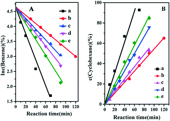 |
| | Fig. 5 (A) Curves of ln![[thin space (1/6-em)]](https://www.rsc.org/images/entities/char_2009.gif) c (benzene) vs. reaction time and (B) curves of c (cyclohexane) vs. reaction time over: (a) Ru/ZrO2, (b) Ru/ZrO2@ZrO2-B(0%), (c) Ru/ZrO2@ZrO2-B(5%), (d) Ru/ZrO2@ZrO2-B(10%) and (e) Ru/ZrO2@ZrO2-B(15%), respectively. c (benzene) vs. reaction time and (B) curves of c (cyclohexane) vs. reaction time over: (a) Ru/ZrO2, (b) Ru/ZrO2@ZrO2-B(0%), (c) Ru/ZrO2@ZrO2-B(5%), (d) Ru/ZrO2@ZrO2-B(10%) and (e) Ru/ZrO2@ZrO2-B(15%), respectively. | |
Table 2 Catalytic kinetic investigation of different Ru-based catalysts
| Catalysts |
k
1 (10−2 min−1) |
k
2 (10−2 mol L−1 min−1) |
k
1/k2 (10−2 L mol−1) |
| Ru/ZrO2 |
4.58 |
192.7 |
2.38 |
| Ru/ZrO2@ZrO2-B(0%) |
1.33 |
51.3 |
2.59 |
| Ru/ZrO2@ZrO2-B(5%) |
1.73 |
63.3 |
2.73 |
| Ru/ZrO2@ZrO2-B(10%) |
2.12 |
84.0 |
2.52 |
| Ru/ZrO2@ZrO2-B(15%) |
2.64 |
105.2 |
2.51 |
3.3 Studies on the structure–property correlation
It has been reported that the Lewis acid site in the ruthenium based catalysts plays a key role in the activated adsorption of benzene;23 therefore, the tuning of the acid site structure and strength would exert an important effect on the selective hydrogenation performance. Py-IR spectra of the Ru/ZrO2 and Ru/ZrO2@ZrO2-B(x%) samples were performed and collected at 373 K (Fig. 6). For all these samples, a band at 1440 cm−1 is observed, which is ascribed to the pyridine adsorbed on the Lewis acid sites. Furthermore, its intensity enhances progressively along with the increase of B doping, indicating that the B-doped ZrO2 shell provides abundant Lewis acid sites. In addition, NH3-TPD was carried out over these samples to explore the strength of the Lewis acid site (Fig. 7). The four Ru/ZrO2@ZrO2-B(x%) samples show two desorption peaks at 190 °C and 255 °C, which are attributed to the weak Lewis acid and medium-strong Lewis acid, respectively. However, the Ru/ZrO2 sample only displays a desorption peak corresponding to a medium-strong Lewis acid site, with the absence of the weak Lewis acid. In the case of the Ru/ZrO2@ZrO2-B(x%) samples, the peak intensity of the medium-strong Lewis acid increases significantly from x = 0 to x = 15%. In contrast, the weak Lewis acid shows a rather different change tendency: this peak is rather small in Ru/ZrO2@ZrO2-B(0%), and its intensity maintains very closely in Ru/ZrO2@ZrO2-B(x%) (x = 5%, 10%, 15%). The results reveal that the introduction of boron doping into the exterior ZrO2 shell provides two types of Lewis acid sites: a concentration-independent weak Lewis acid and a concentration-dependent medium-strong Lewis acid. The former is possibly related to the ZrO2 structure modified by boron doping while the latter originates from the accumulation of boron species. The integral area ratio of the weak to medium-strong Lewis acid, Sweak/Smedium-strong, is 0.57, 0.47, and 0.45 for Ru/ZrO2@ZrO2-B(x%) (5%, 10%, 15%); the Ru/ZrO2@ZrO2-B(5%) exhibits the largest Sweak/Smedium-strong value, in agreement with its optimal selectivity toward cyclohexene. The results indicate that the weak Lewis acid site in the B-doped ZrO2 shell gives a predominant contribution to the activated adsorption of benzene and/or the desorption of cyclohexene. In order to give a further insight into the activated adsorption of the reactant, benzene temperature-programmed desorption (Benz-TPD) was carried out to investigate the adsorption behavior of benzene over these Ru-based catalysts (Fig. 8A). For the sample of Ru/ZrO2 (Fig. 8A-a), two desorption peaks of benzene are observed at 277 °C and 301 °C, which can be attributed to desorption from the ZrO2 carrier and from the Ru surface, respectively. This is further confirmed by the Benz-TPD curve over Ru/ZrO2@ZrO2(0%), from which only one desorption peak at 277 °C is detected. As a result, the activated adsorption of benzene only occurs on the B-doped ZrO2 shell, accounting for the single desorption peak at 277 °C for Ru/ZrO2@ZrO2(0%). Notably, for the three samples of Ru/ZrO2@ZrO2-B(x%) (x = 5%, 10%, 15%) (from Fig. 8A-c to A-e), the desorption peak shifts to a higher temperature relative to Ru/ZrO2@ZrO2(0%) (308 °C vs. 277 °C), indicating the doping of boron (i.e., the tunability of the Lewis acid sites) enhances the activated adsorption of benzene on the catalyst surface. In addition, the intensity of the desorption peak enhances obviously upon increasing the amount of boron doping, which could be due to the benzene desorption from the Lewis acid sites. As the reaction of benzene hydrogenation follows first order reaction kinetics, the increment in Lewis acid sites density on the surface of the catalyst leads to an increased concentration of adsorbed benzene, and thus effectively accelerates the reaction rate of benzene. This is in accordance with the values of k1 and k2 over the Ru/ZrO2@ZrO2-B(x%) (x = 5%, 10%, 15%) samples (Table 2).
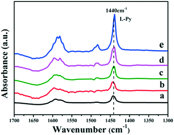 |
| | Fig. 6 Py-IR spectra of (a) Ru/ZrO2, (b) Ru/ZrO2@ZrO2-B(0%), (c) Ru/ZrO2@ZrO2-B(5%), (d) Ru/ZrO2@ZrO2-B(10%) and (e) Ru/ZrO2@ZrO2-B(15%) at 373 K, respectively. | |
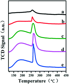 |
| | Fig. 7 NH3-TPD profiles of (a) Ru/ZrO2, (b) Ru/ZrO2@ZrO2-B(0%), (c) Ru/ZrO2@ZrO2-B(5%), (d) Ru/ZrO2@ZrO2-B(10%) and (e) Ru/ZrO2@ZrO2-B(15%), respectively. | |
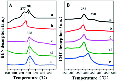 |
| | Fig. 8 TPD profiles of benzene (A) and cyclohexene (B) on (a) Ru/ZrO2, (b) Ru/ZrO2@ZrO2-B(0%), (c) Ru/ZrO2@ZrO2-B(5%), (d) Ru/ZrO2@ZrO2-B(10%) and (e) Ru/ZrO2@ZrO2-B(15%), respectively. | |
It is well known that the desorption performance of the cyclohexene molecule significantly affects the reaction selectivity, for example, a facile desorption favours its selectivity. Therefore, cyclohexene temperature-programmed desorption (CHE-TPD) over these samples was further studied (Fig. 8B). For Ru/ZrO2 (Fig. 8B-a), as expected, two desorption peaks of cyclohexene at 287 °C and 350 °C appear, which belong to desorption from the surface of ZrO2 and from the metal Ru, respectively. For the porous ZrO2-coated ruthenium catalyst Ru/ZrO2@ZrO2(0%) (Fig. 8B-b), only one desorption peak is observed at a low temperature (286 °C), without the contact between cyclohexene and metal Ru owing to the shielding effect of the ZrO2 shell. Moreover, the desorption peak of cyclohexene shifts to a higher temperature (from 287 °C to 315 °C) as the content of doped-B increases from 5 to 15%, indicating a depressed desorption of cyclohexene. This can be explained as follows: the medium-strong acid site with increased density shows a strong interaction with cyclohexene and inhibits its desorption, which facilitates the deep hydrogenation of cyclohexene to cyclohexane. As a result, with the increment of boron content in ZrO2 shell, the k2 value increases dramatically, accompanied with the decrease of cyclohexene selectivity (as shown in Table 2). Finally, the reusability of the optimal catalyst, Ru/ZrO2@ZrO2(5%), was tested. After each catalytic run, the organic phase was cleared under vacuum and the residual catalyst suspension was reused in a successive run without further reactivation. The catalyst underwent little activity and selectivity loss, within 2%, after three recycles (Fig. S4†).
DFT calculations were performed to study the adsorption energies of benzene and cyclohexene on a pristine ZrO2(−111) surface and a B-doped ZrO2(−111) surface, respectively (Fig. 9). The adsorption energy of benzene decreases from 0.35 eV to −0.01 eV after the doping of B, with an energy change of −0.36 eV. In contrast, the adsorption energy of cyclohexene decreases from −0.02 to −0.06 eV, with an energy change of −0.04 eV. This indicates that both benzene and cyclohexene adsorb more strongly on a B-doped ZrO2(−111) surface than on a pristine ZrO2(−111) surface. However, the doping of B facilitates the benzene adsorption more significantly relative to the cyclohexene adsorption, accounting for the enhanced selectivity toward cyclohexene as shown in the experimental section. As a balance between the activated adsorption of benzene and desorption of cyclohexene, the sample of Ru/ZrO2@ZrO2(5%) exhibits the maximal selectivity toward cyclohexane.
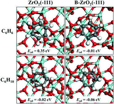 |
| | Fig. 9 Adsorption structures and adsorption energies of benzene and cyclohexene on a pristine ZrO2(−111) surface and a B-doped ZrO2(−111) surface, respectively. The white, gray, red, cyan and pink ball represents H, C, O, Zr and B, respectively. | |
4. Conclusions
In summary, a new Ru-based catalyst for selective hydrogenation of benzene to cyclohexene was synthesized by coating a porous B-doped ZrO2 layer on the surface of Ru/ZrO2 particles. The resulting Ru/ZrO2@ZrO2-B(5%) sample exhibits the best catalytic performance (benzene conversion: 53.1%; cyclohexene selectivity: 58.8%) without using any additives. Py-IR and NH3-TPD show that Ru/ZrO2@ZrO2-B(5%) possesses the largest Sweak/Smedium-strong value; and Benz-TPD and CHE-TPD confirm that a promoted activated adsorption of benzene and improved desorption of cyclohexene occur on the surface of Ru/ZrO2@ZrO2-B(5%), accounting for its optimal selectivity toward cyclohexene. This work provides an understanding of the synergistic catalysis between metal Ru and the acid sites of the carrier, which can be extended to the exploration of other heterogeneous catalysts.
Conflicts of interest
There are no conflicts to declare.
Acknowledgements
This work was supported by the National Key Research and Development Program (Grant No. 2017YFA0206804), the National Natural Science Foundation of China (NSFC) and the Fundamental Research Funds for the Central Universities (buctylkxj01).
Notes and references
- S. O. Lee, R. Raja, K. D. Harris, J. M. Thomas, B. F. Johnson and G. Sankar, Angew. Chem., 2003, 115, 1558–1561 CrossRef.
- H. Spod, M. Lucas and P. Claus, ChemCatChem, 2016, 8, 2659–2666 CrossRef CAS.
- K. Sato, M. Aoki and R. Noyori, Science, 1998, 281, 1646–1647 CrossRef CAS PubMed.
- L. Foppa and J. Dupont, Chem. Soc. Rev., 2015, 44, 1886–1897 RSC.
- Q. Zhang, X. Yan, P. Zheng and Z. Wang, Chin. J. Chem. Eng., 2016, 25, 294–300 CrossRef.
- S. Nandanwar, A. Dabbawala, M. Chakraborty, H. Bajaj, S. Mukhopadhyay and K. Shenoy, Res. Chem. Intermed., 2016, 42, 1557–1569 CrossRef CAS.
- J. Liu, C. Li, F. Wang, S. He, M. Wei, D. G. Evans and X. Duan, J. Mater. Chem. A, 2014, 2, 7570–7577 CAS.
- G. Zhou, R. Dou, H. Bi, S. Xie, Y. Pei, K. Fan, M. Qiao, B. Sun and B. Zong, J. Catal., 2015, 332, 119–126 CrossRef CAS.
- P. Kluson and L. Cerveny, Appl. Catal., A, 1995, 128, 13–31 CrossRef CAS.
- J. Wang, Y. Wang, S. Xie, M. Qiao, H. Li and K. Fan, Appl. Catal., A, 2004, 272, 29–36 CrossRef CAS.
- X. Zhou, H. Sun, W. Guo, Z. Liu and S. Liu, J. Nat. Gas Chem., 2011, 20, 53–59 CrossRef CAS.
- Z. Peng, X. Liu, H. Lin, Z. Wang, Z. Li, B. Li, Z. Liu and S. Liu, J. Mater. Chem. A, 2016, 4, 17694–17703 CAS.
- W. Gao, Y. Zhao, H. Chen, H. Chen, Y. Li, S. He, Y. Zhang, M. Wei, D. G. Evans and X. Duan, Green Chem., 2015, 17, 1525–1534 RSC.
- M. Hossain, K. Sedor and H. De Lasa, Chem. Eng. Sci., 2007, 62, 5464–5472 CrossRef CAS.
- H. L. Jiang, T. Akita, T. Ishida, M. Haruta and Q. Xu, J. Am. Chem. Soc., 2011, 133, 1304–1306 CrossRef CAS PubMed.
- T. Yamaguchi, Catal. Today, 1994, 20, 199–217 CrossRef CAS.
- M. D. Rhodes and A. T. Bell, J. Catal., 2005, 233, 198–209 CrossRef CAS.
- K. D. Jung and A. T. Bell, J. Catal., 2000, 193, 207–223 CrossRef CAS.
- A. Möller and H. Hahn, Nanostruct. Mater., 1999, 12, 259–262 CrossRef.
- B. Q. Xu, J. M. Wei, Y. T. Yu, J. L. Li and Q. M. Zhu, Top. Catal., 2003, 22, 77–85 CrossRef CAS.
- D. Hoang and H. Lieske, Catal. Lett., 1994, 27, 33–42 CrossRef CAS.
- F. Su, Q. Wu, D. Song, X. Zhang, M. Wang and Y. Guo, J. Mater. Chem. A, 2013, 1, 13209–13221 CAS.
- G. Zhou, Y. Pei, Z. Jiang, K. Fan, M. Qiao, B. Sun and B. Zong, J. Catal., 2014, 311, 393–403 CrossRef CAS.
- X. Xue, J. Liu, D. Rao, S. Xu, W. Bing, B. Wang, S. He and M. Wei, Catal. Sci. Technol., 2017, 7, 650–657 CAS.
- H. Pham and L. Wang, Phys. Chem. Chem. Phys., 2015, 17, 11908–11913 RSC.
- R. Prins, Chem. Rev., 2012, 112, 2714–2738 CrossRef CAS PubMed.
- S. Lee, K. Lee, J. Im, H. Kim and M. Choi, J. Catal., 2015, 325, 26–34 CrossRef CAS.
- G. Zhou, X. Tan, Y. Pei, K. Fan, M. Qiao, B. Sun and B. Zong, ChemCatChem, 2013, 5, 2425–2435 CrossRef CAS.
Footnotes |
| † Electronic supplementary information (ESI) available. See DOI: 10.1039/c7cy01351e |
| ‡ These authors contributed equally to this work and should be considered as co-first authors. |
|
| This journal is © The Royal Society of Chemistry 2018 |
 *
*
![[thin space (1/6-em)]](https://www.rsc.org/images/entities/char_2009.gif) :
:![[thin space (1/6-em)]](https://www.rsc.org/images/entities/char_2009.gif) 9, v/v) at 400 °C for 3 h to obtain the Ru/ZrO2 catalyst precursor.
9, v/v) at 400 °C for 3 h to obtain the Ru/ZrO2 catalyst precursor.
![[thin space (1/6-em)]](https://www.rsc.org/images/entities/char_2009.gif) :
:![[thin space (1/6-em)]](https://www.rsc.org/images/entities/char_2009.gif) 9, v/v) at 400 °C for 3 h. After cooling down to room temperature, the carrier gas (argon for H2-TPD; helium for CO-TPD, Benz-TPD and CHE-TPD) was purged for 1 h to remove the physically adsorbed H2 on the surface of the sample. Finally, the carrier stream was introduced at a rate of 50 mL min−1 with a heating rate of 10° min−1 for the collection of the desorption signal.
9, v/v) at 400 °C for 3 h. After cooling down to room temperature, the carrier gas (argon for H2-TPD; helium for CO-TPD, Benz-TPD and CHE-TPD) was purged for 1 h to remove the physically adsorbed H2 on the surface of the sample. Finally, the carrier stream was introduced at a rate of 50 mL min−1 with a heating rate of 10° min−1 for the collection of the desorption signal.


